Electronics Design
Understand circuit design rules, PCB milling, and create a echo board
01 Group Assignment
//
Observe the operation of a microcontroller circuit board
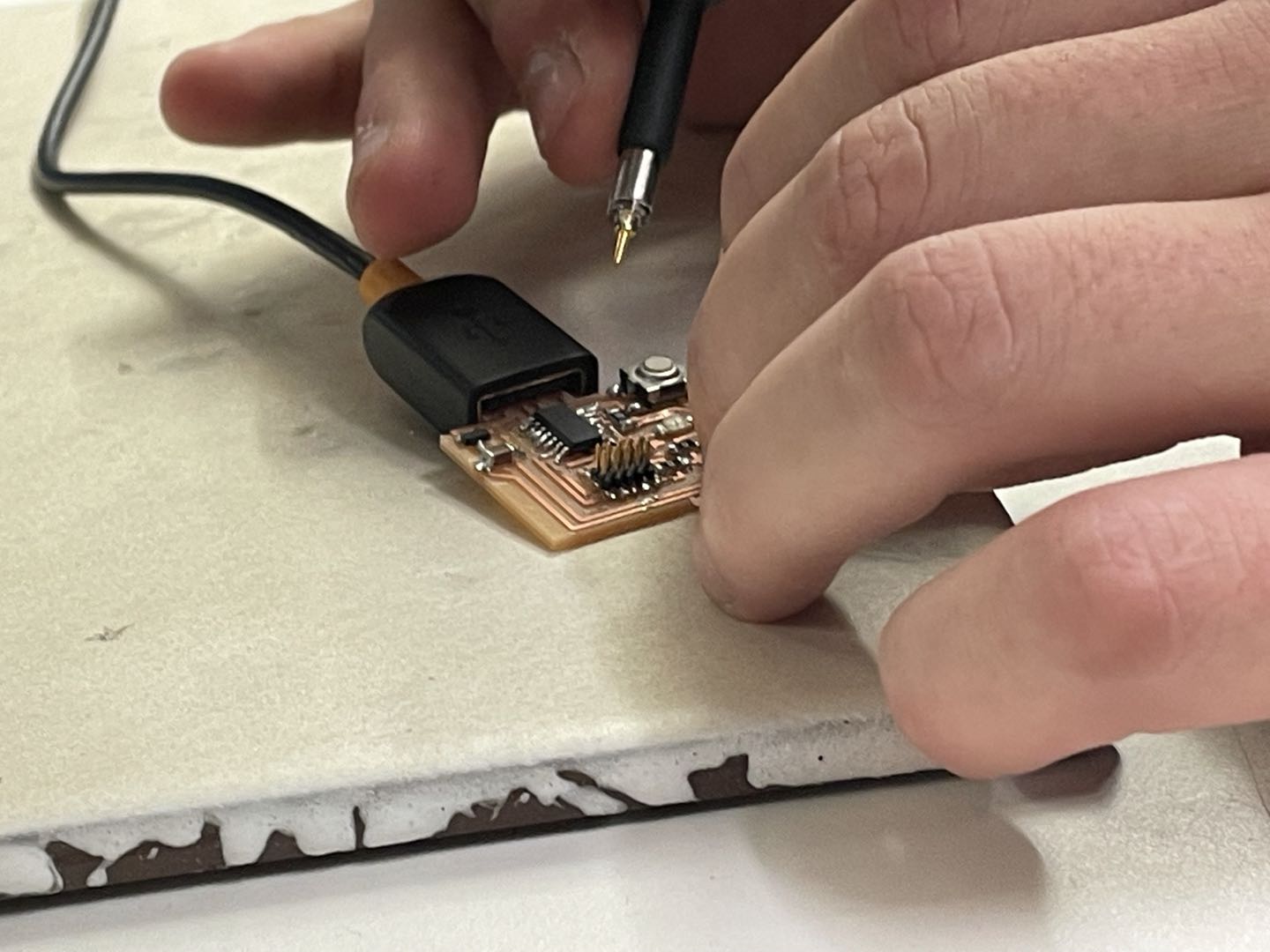
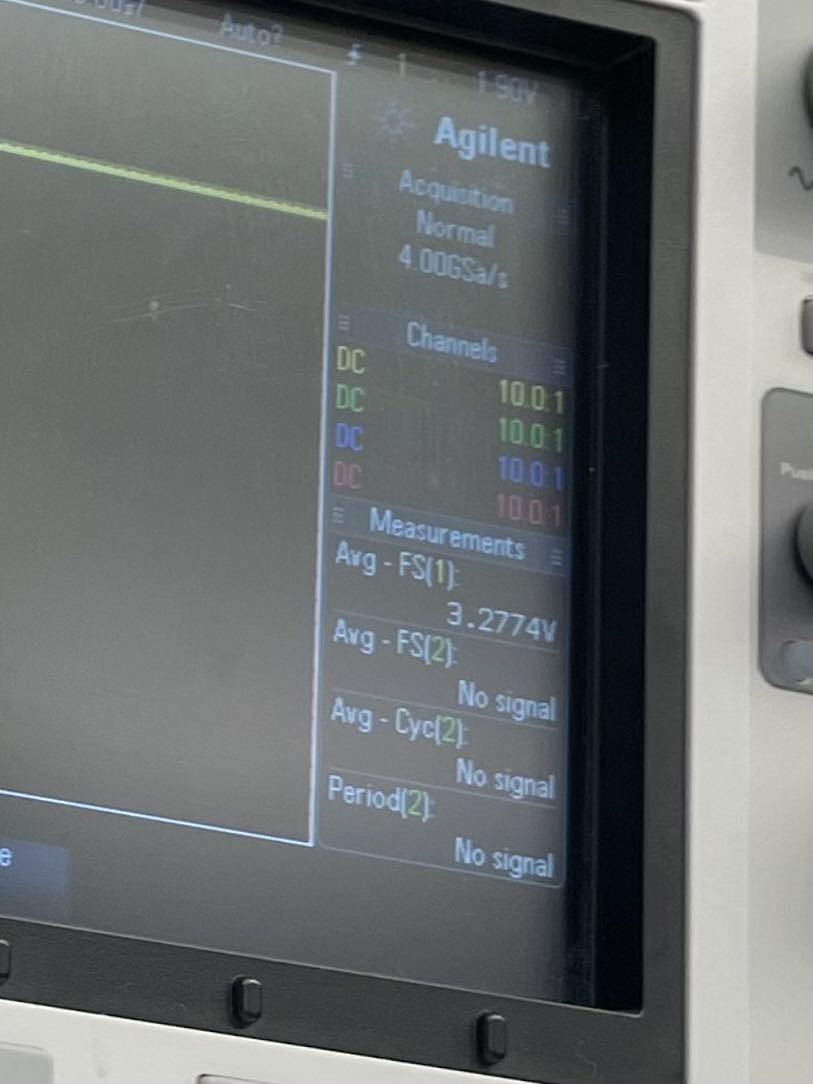
There are many ways to obeserve and test a microcontroller circuit board. We can either use a multimeter to measure the current flow or really get in depth and look at signal voltages across different points using a oscilloscope. For the group assignment, we used a oscilloscope to measure the power across the circuit and checked the voltages (A BIG SHOUT OUT TO ANTHONY WHO HELPED US WITH USING THE OSCILLOSCOPE). Since I made a D11C microcontroller board with a power regulator, the power should be around 3.3V. We touched one point to the GND as reference and the other end at the power trace and we did get close value to 3.3.
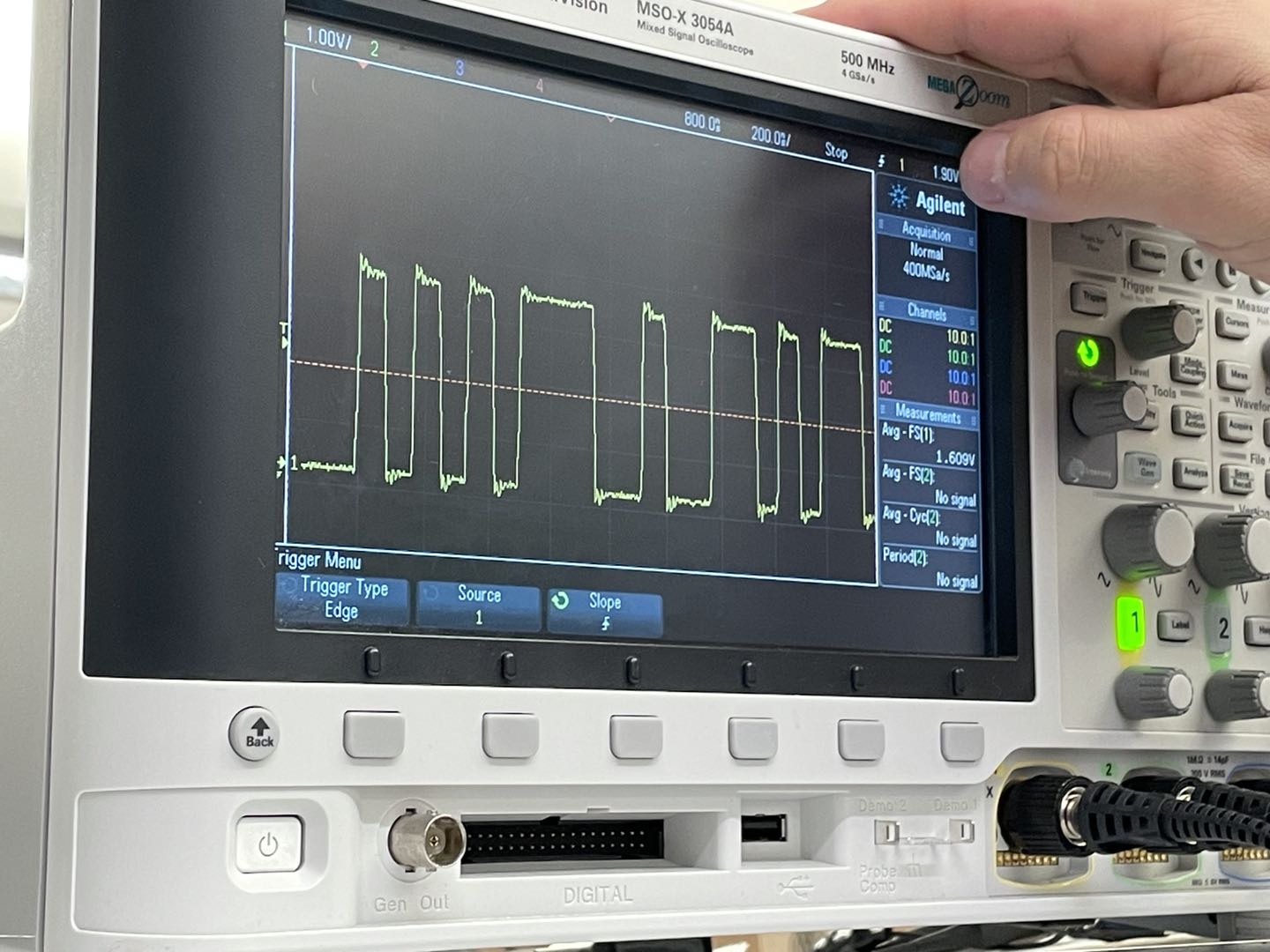
Anthony also showed us the results of measuring DC voltage, and we got a rectangular wave. These rectangular waves are often used and observed in digital electronics operations.
02 Individual Assignment
//
Redraw and make a echo hello world board
For this week, I decided to make 2 echo boards: ATtiny1614 and D11C with 10 pins. The difference is that making the ATtiny1614 requires a USB-UPDI translator in order to communicate with the computer. D11C 10pins doesn't need the adaptor and can be directly programmed from the programmer (which will be much easier for the bootloader process). Before getting started with making, I really wanted to understand what are the functions of each component on the echo board. I started the process by looking at the Atiny1614 and D11C microcontroller data sheets.
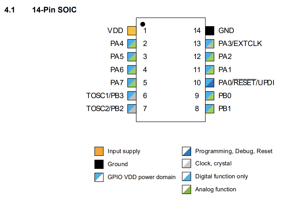
This is the pinout diagram for ATtiny1614, and there are 14pins. The VDD and GND just represent the ports that needed to connect the power and groud. The PA0 is used for programming and reset.
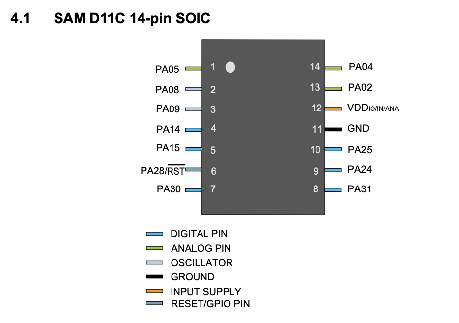
This is the pinout diagram for D11C, and it also has the pins for ground, power, and reset. The difference between these two is that the pins on ATtiny can be digital or analog, but the pins on D11C are ethier analog or digital.
So my understanding at this point is that if we are going to add a LED and a button to the board, we basically just need to connect these two new components to the floating pins with necessary resistors. I started the process using eagle, which is a electronics design tool embedded inside of Fusion.
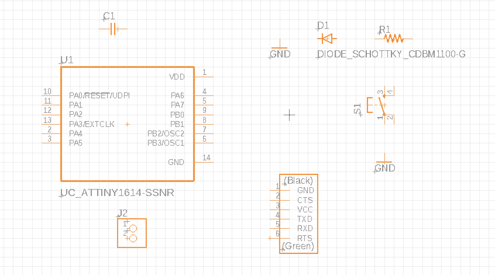
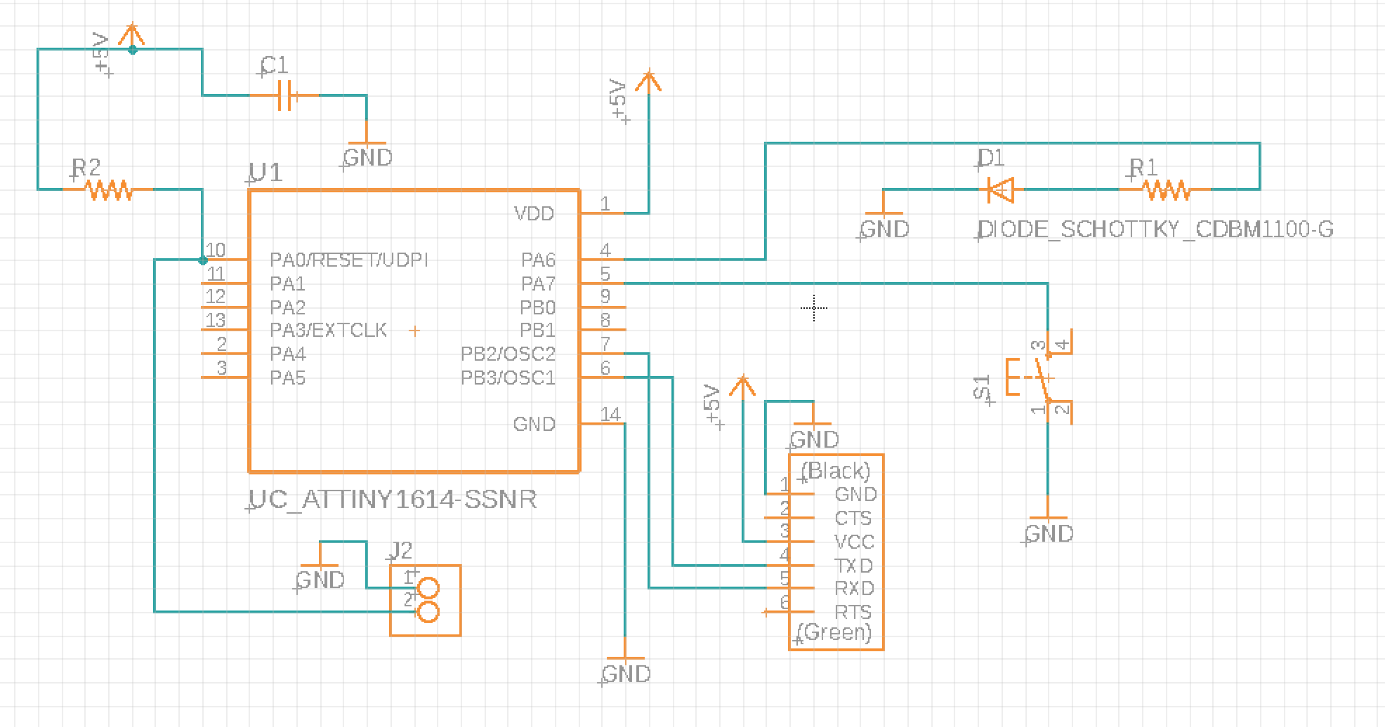
I downloaded the engle library from class website and started mapping all of the neccesary components onto the canvas. These are for the ATtiny1614. For the LED, I added a current limiting resistor of 1k to it and connected the other end to the groud. Another very helpful library is called "supply", which you can get from the eagle library. It has GND and power arrows so that you don't need to draw lines between eveything.
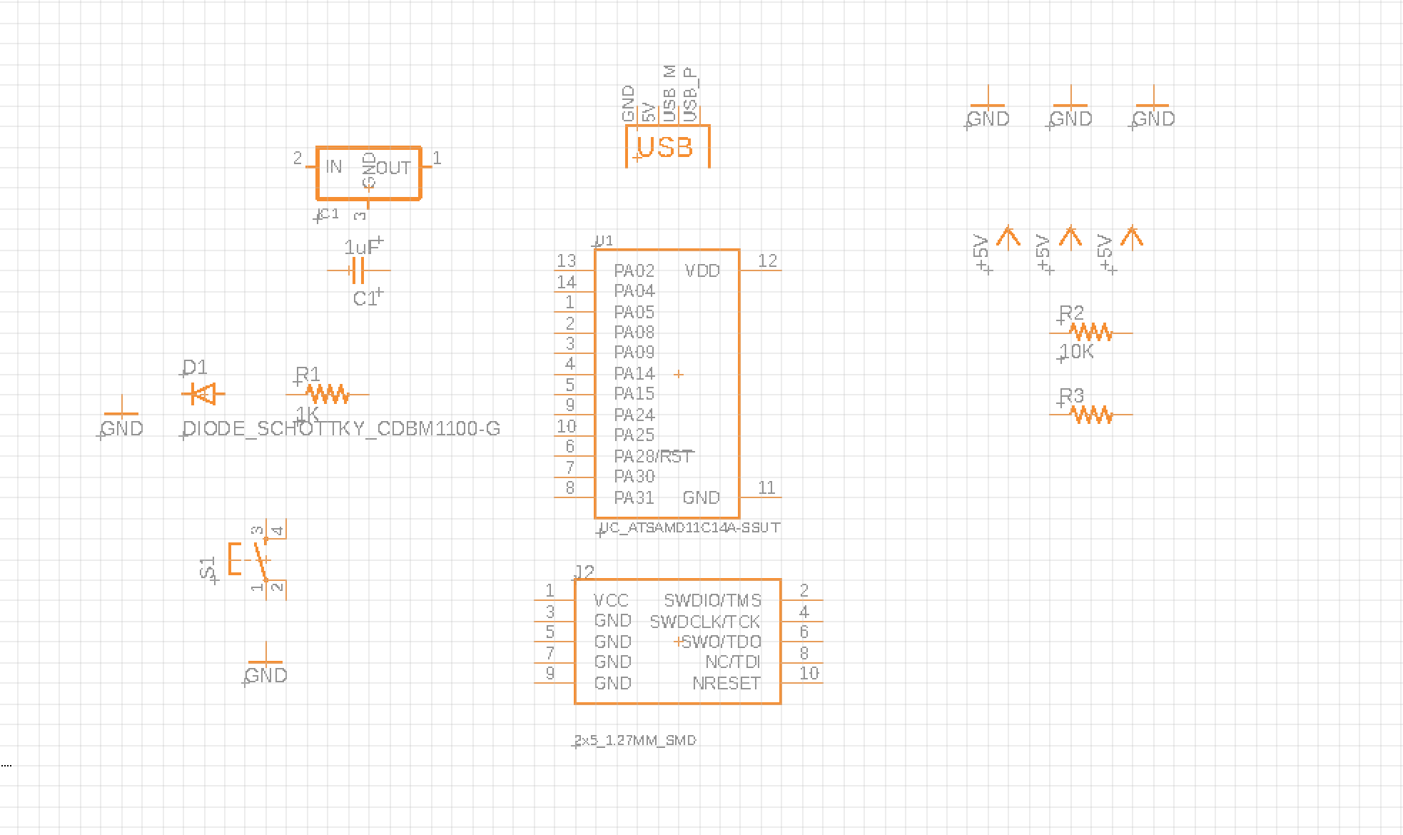
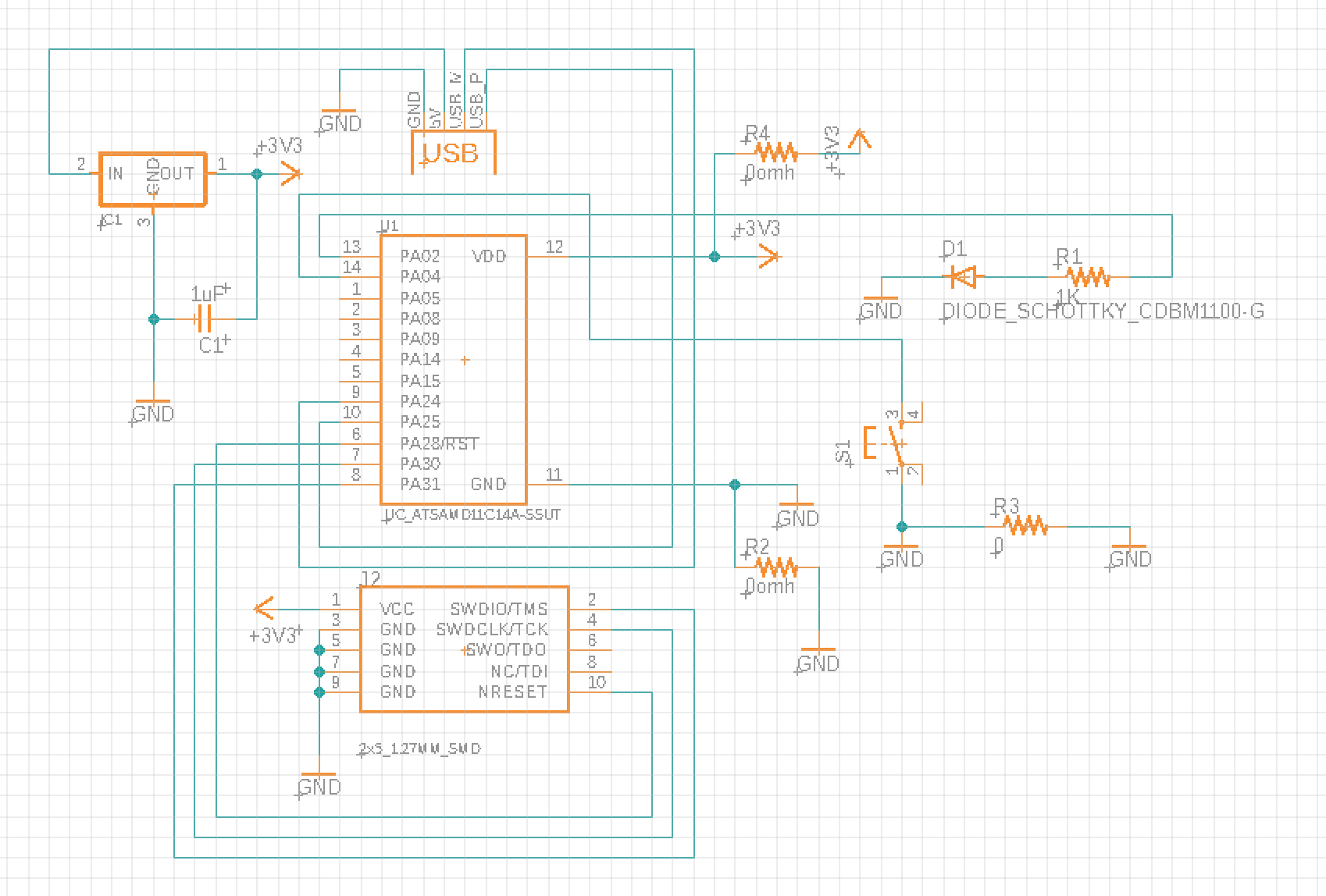
For the D11C echo board, I did everything much faster than scheming the ATtiny1614. One thing to keep in mind is that D11C requires a voltage regulator, which means all of the power needed in other components should be the output of the regulator, not 5V.
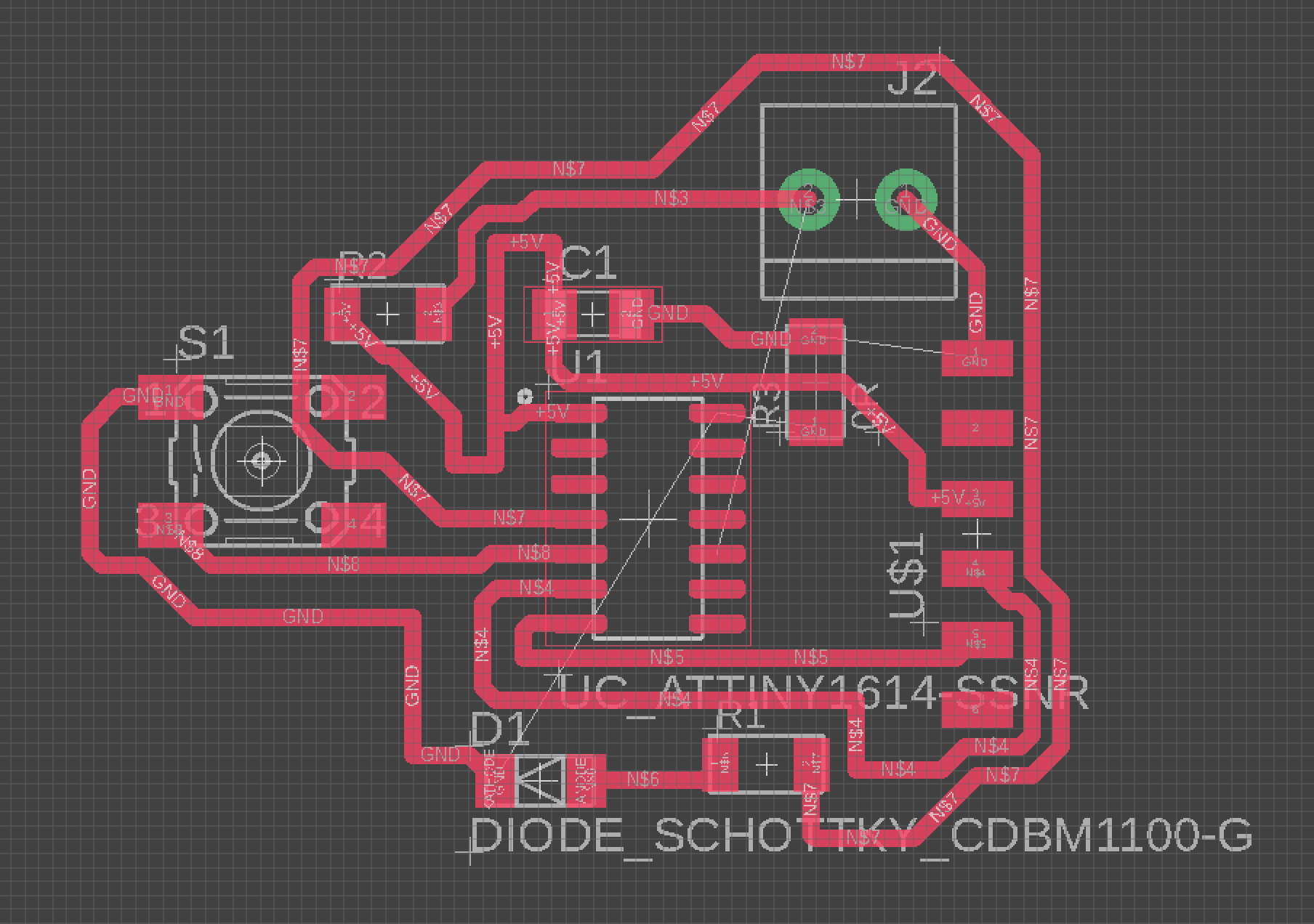
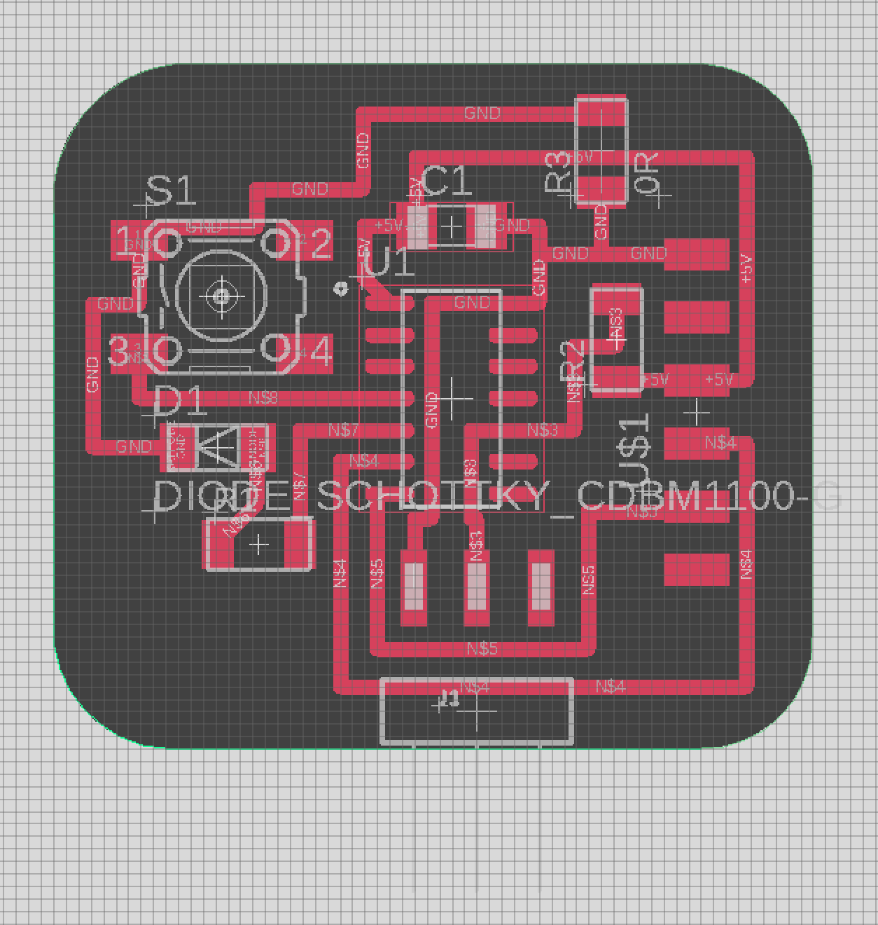
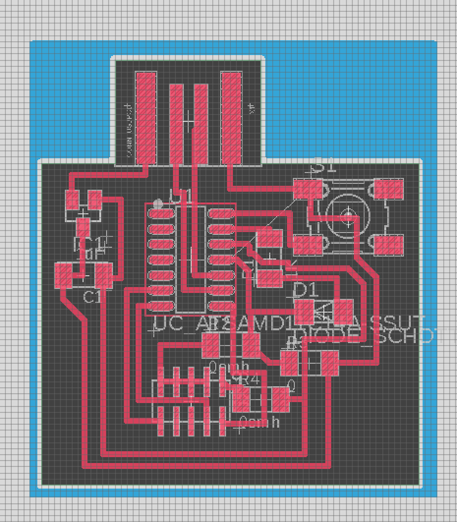
The first two image is the routing I did in eagle for ATtiny, you can see that the left one wasted a lot more area than the second one I did. It can take a long time and a lot of practice to route and find a best solution to not waste material in between. The third image is the routing for D11C, and it got much tighter. It turned out that I actually really enjoyed the routing process.
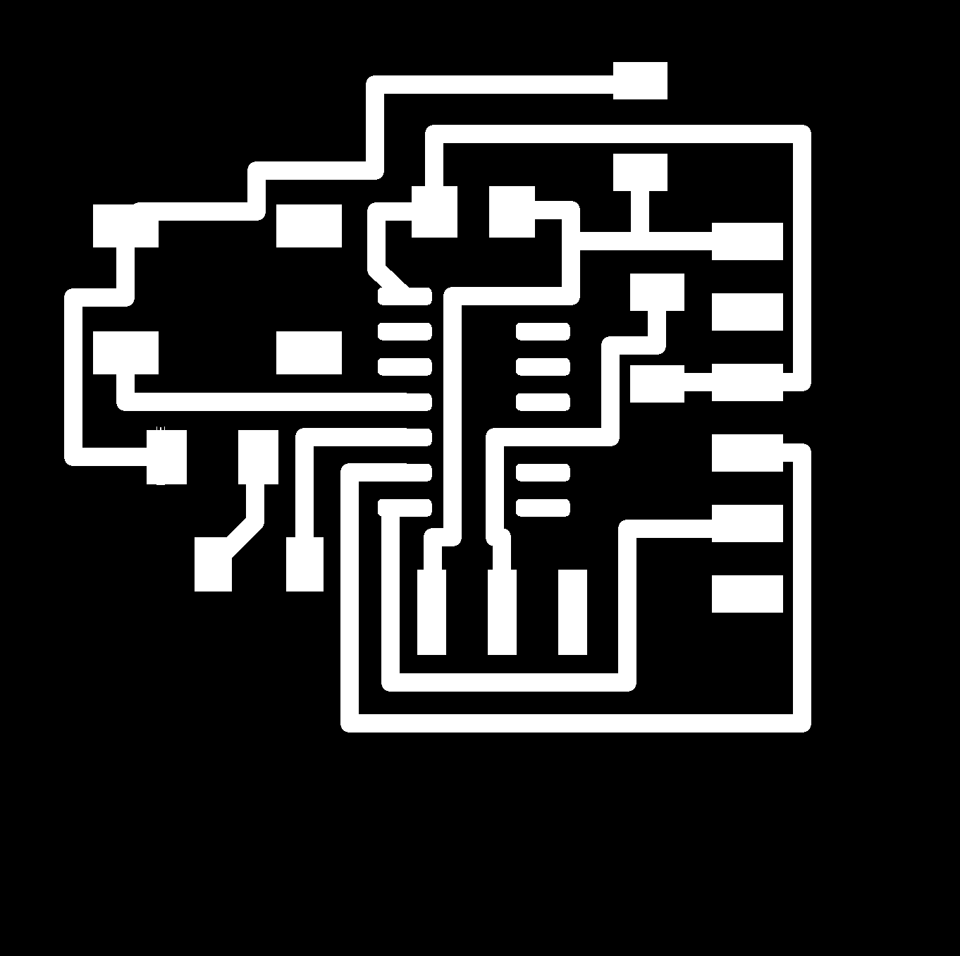
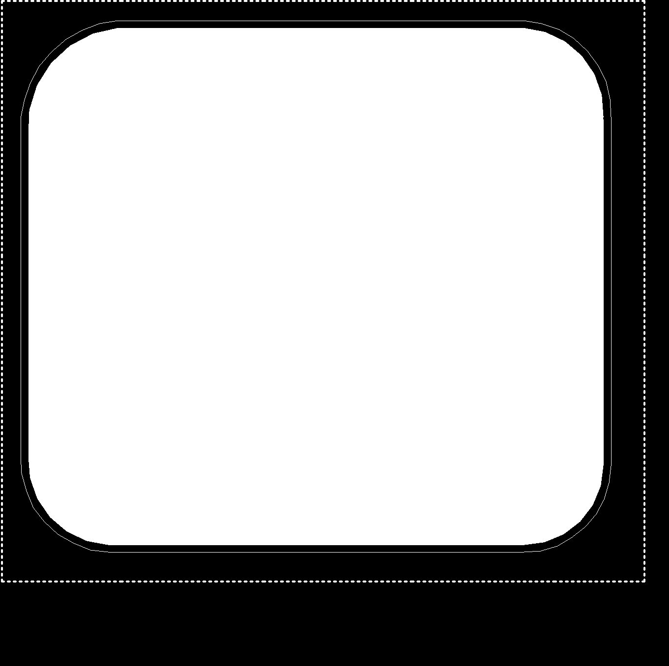
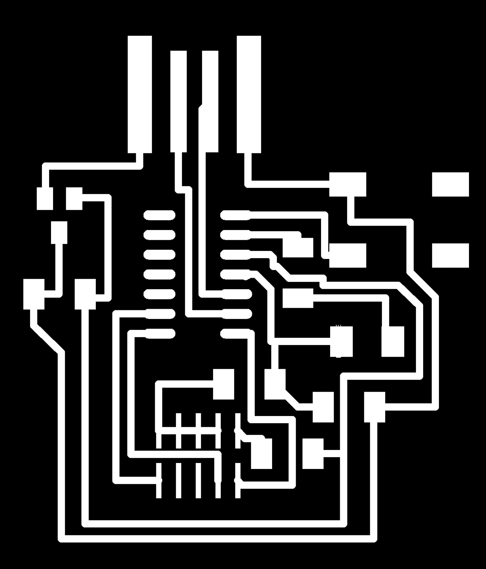

Here are the final traces for the ATtiny and D11C board (ANOTHER BIG SHOUT OUT TO JAKE'S EAGLE TUTORIAL). We basically just need to use a few simple commands to export the monochrome image. However, I don't know why the outline I exported is inverted. It was a easy fix in mods just by clicking invert. In terms of ratio and sizing, I exported form eagle as 500 dpi, and then changed the dpi to 1000, and that worked fine. I am not sure what is the legit way to making sure the sizing and proportion correct, but doubling the dpi in mods did work out.
***MISTAKE ALERT: Before revealing my milled boards, I want to share a mistake I did in routing process for the D11C board. I forgot to load the fab.dru before I start routing, so the lines got really close becasue the contraints are not set to the correct spacing and width. It is crucial to load the drc before routing so that eagle will tell where you can get the trace in and where you cannot.
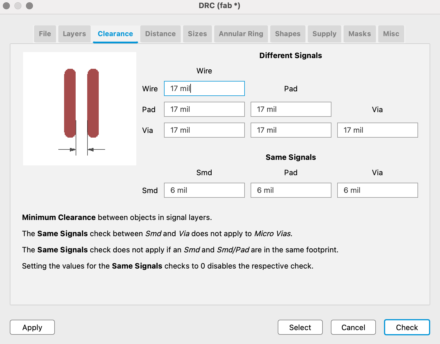
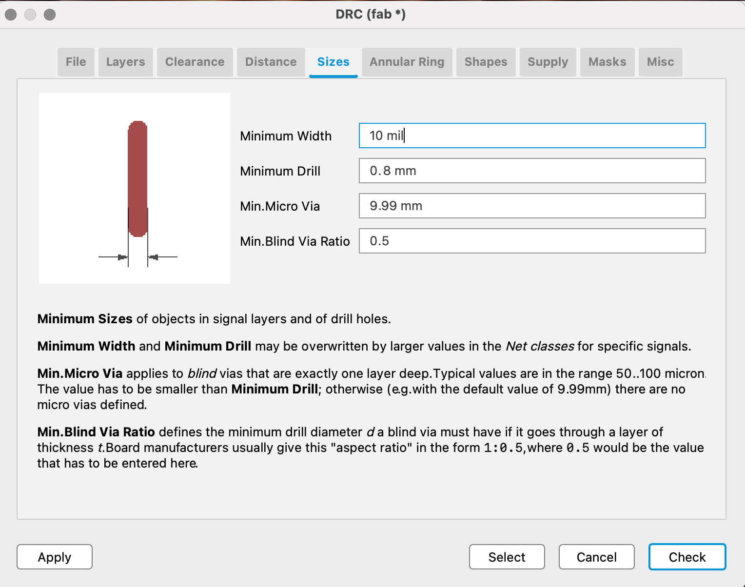
Remember to load these settings before you start routing!
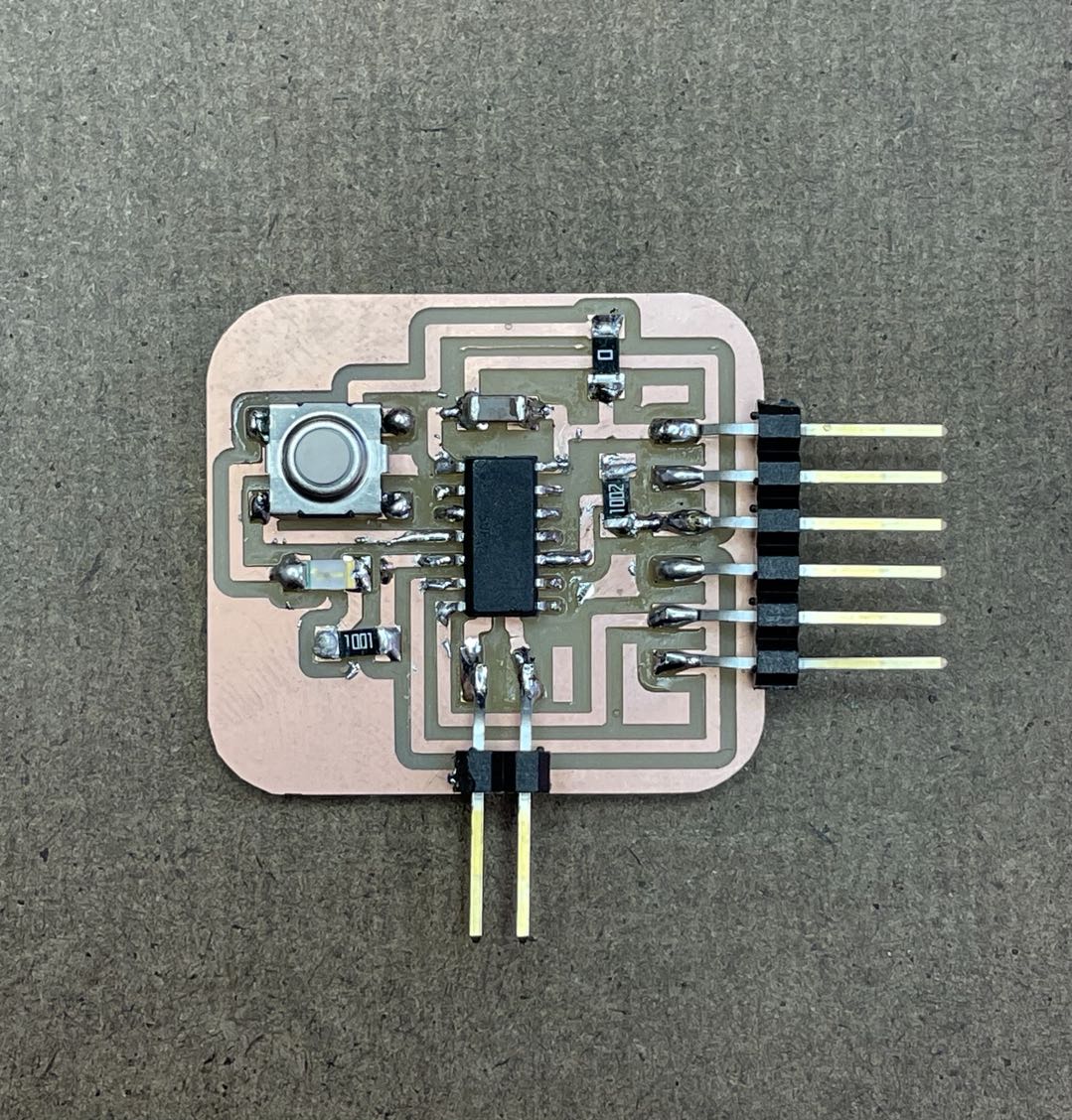
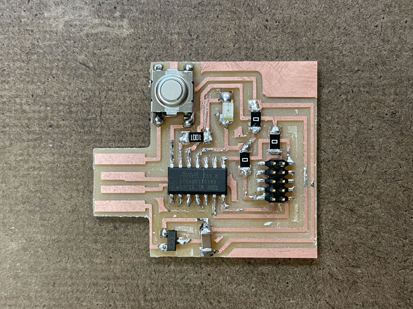
These is the ATtiny board and it actually came out nice and clean! I did load the drc before I start so the routing do follow the constraints. I later stuffed it with all the needed components. This time was so much easier to find the components because I finally understood what are the meaning of those abbreviated names.
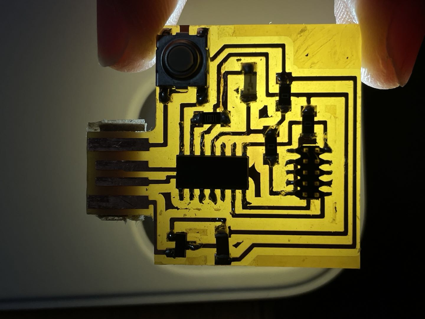
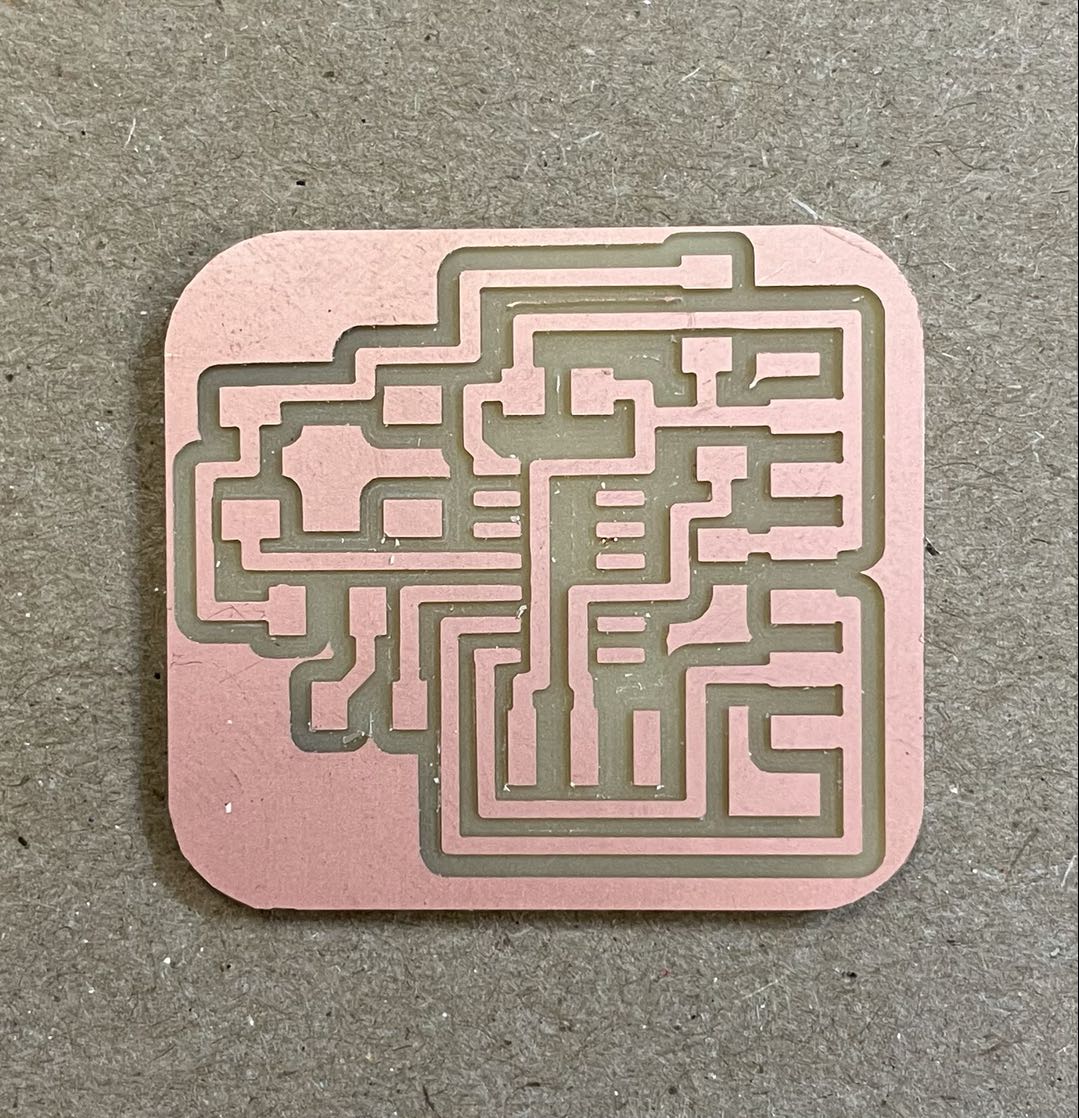
On the other hand, the D11C board didn't turn out as well because of the drc problem, so the mill couldn't distinct some of the traces. I had to user a blaze to scrape off some parts. I wasn't sure if all the traces are clean but we will see if it is going to work in the testing process. Another trick I learned from Anthony is that you can put a flashlight below the board to see if all of the traces are clean and distinct.
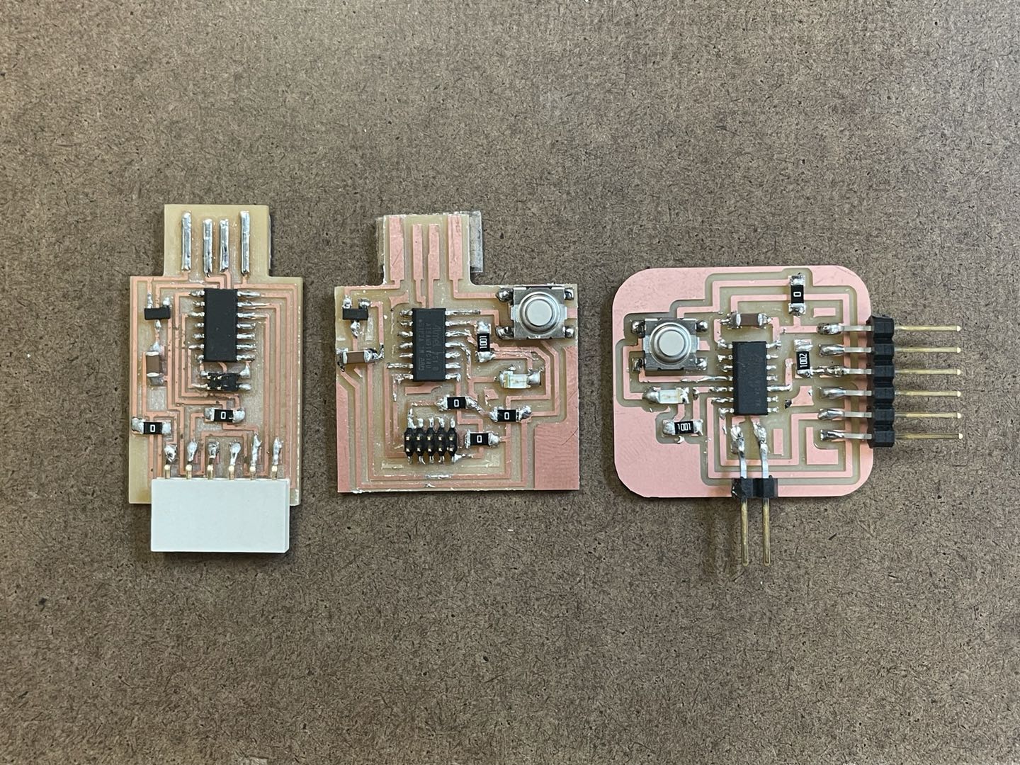
Another thing that is interesting to look at is the width of the trace. For the three boards I made until now, all of them have different width. The ATtiny has 0.6096mm; D11C has ~0.4mm; and the D11c programmer we did 2 weeks ago has ~0.254mm. It turns out ~0.25mm would work and can save a lot of spaces. With a width of 0.6096mm, the board will take up more spaces but it is easier to read.
//
Test the echo board
Now that we have the echo boards ready, it is time to test them. In orde to program it, we have to load a bootloader onto the microcontroller. I decided to test the D11C echo board because it doesn't require any adaptor.
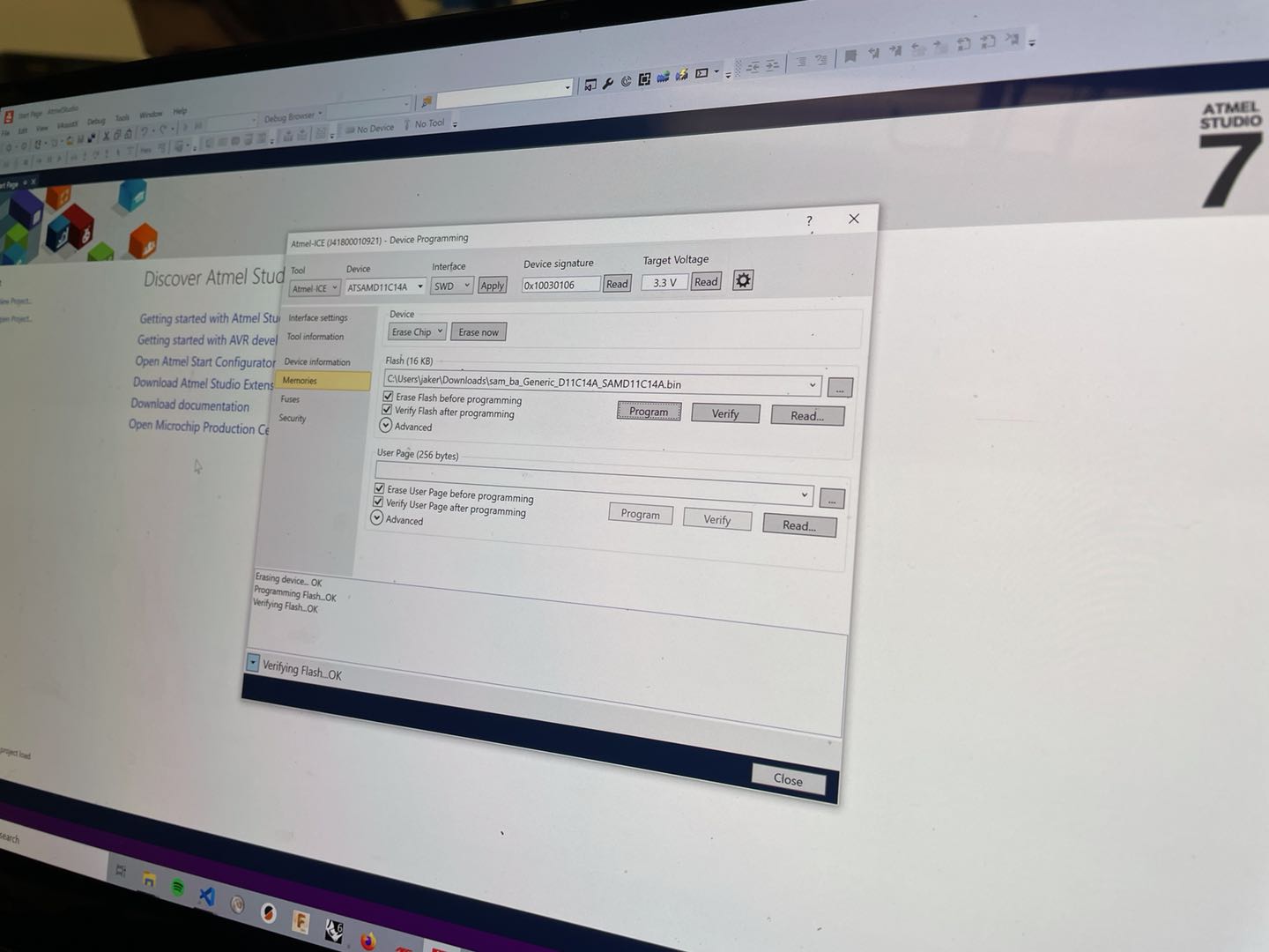
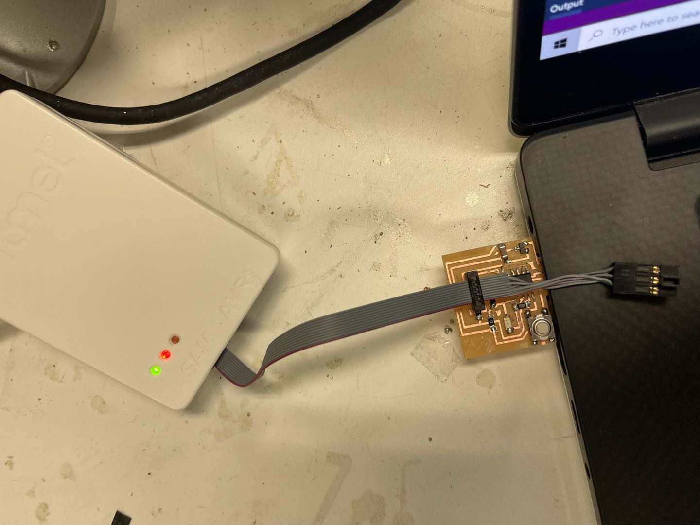
(ONE MROE SHOUT OUT TO JAKE FOR HELPING WITH LOADING THE BOOTLOADR) Jake loaded my board with arduino bootloader using the Atmel-ICE programmer. The computer did recognize my board which means it did work. It was such a relief!! Once the bootloader is up there, this little board will just act like a tiny arduino.
The next step for testing is to add D11C board to the arduino board manager, and it will racognize it once I plug it into my computer.
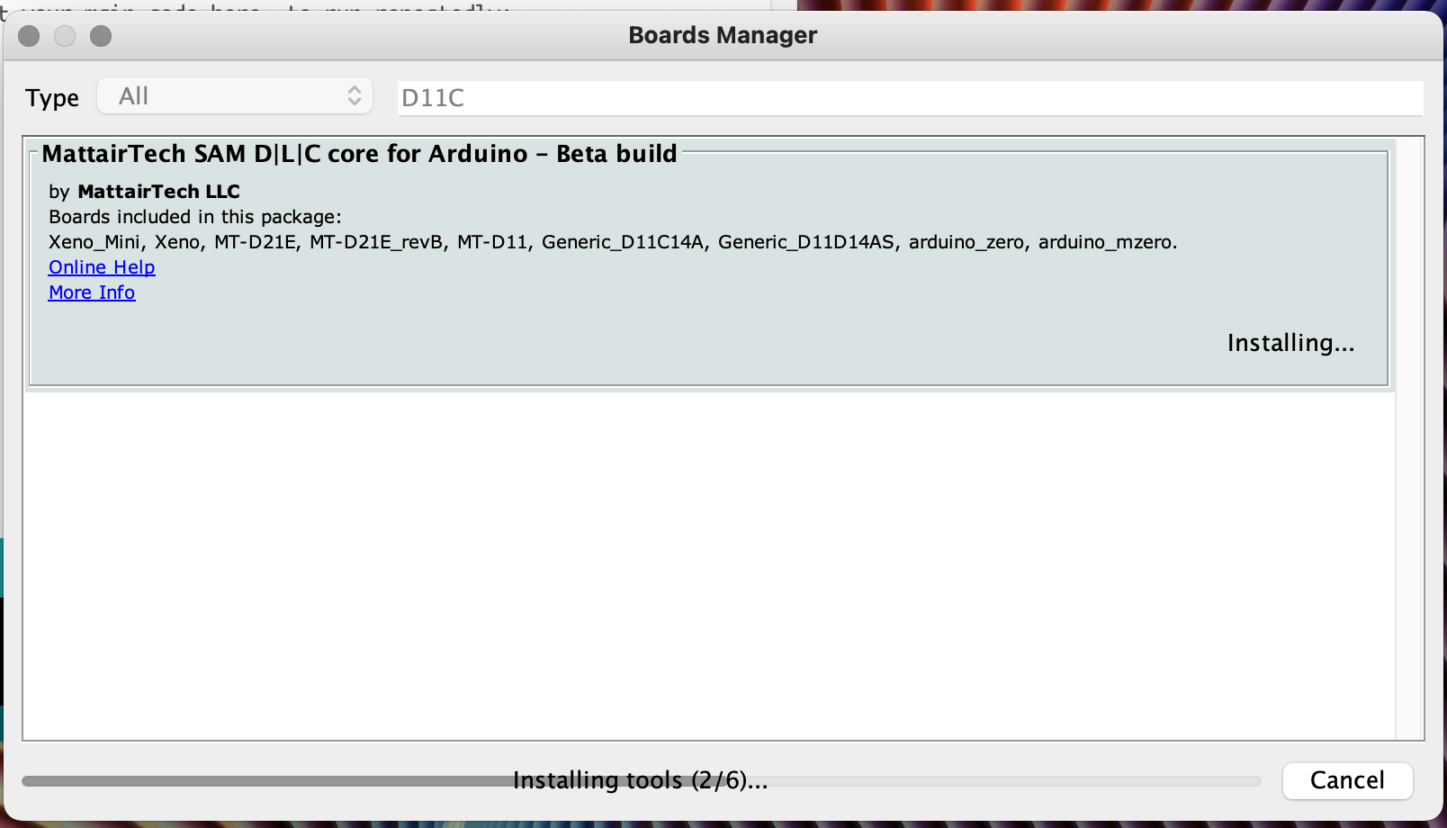
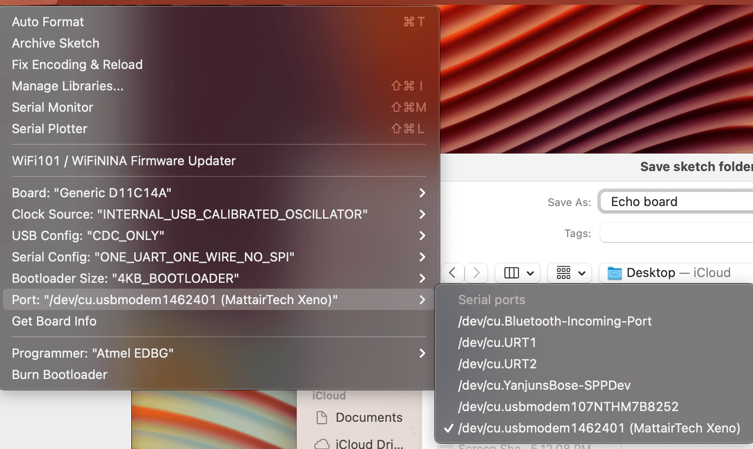
I copied the MattairTech D11C board installation link to the board manager and installed it. We have to use the correct board that corresponds to the microcontroller in order to upload program on there. Once I have the board set up correctly, when I plug the board in, there should a new port showing up in the ports setting.
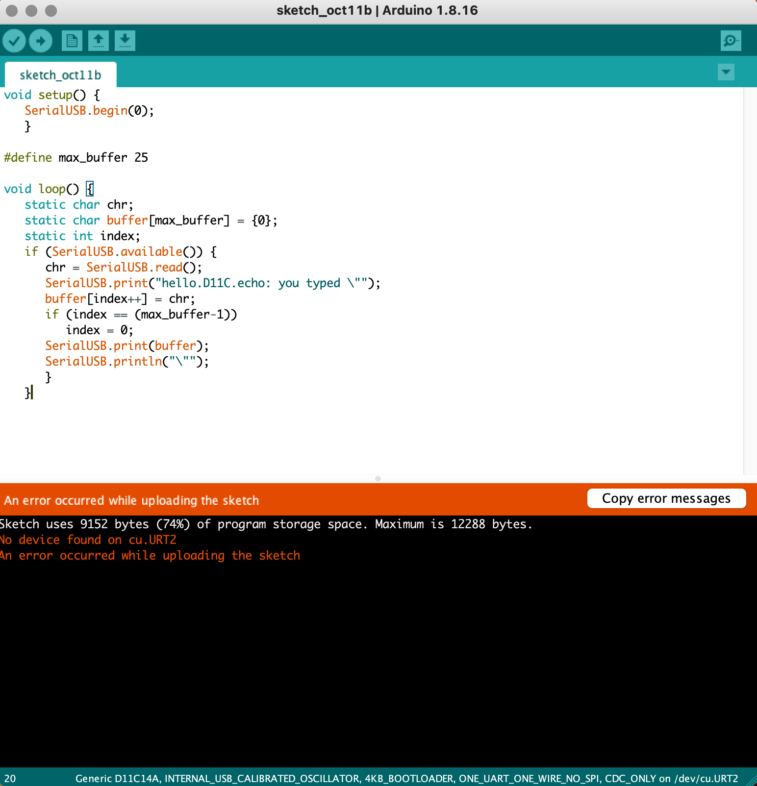
A problem I encountered during the process is arduino just cannot recognize my microcontroller. Anthony helped me with using the multimeter and check if there was anything wrong with the board. Now I am slowly getting the debugging process for electronics. We always want to narrow the problem step by step. Fortunately everything on my board looks fine, so I tried to plugged back in again, and the port just magically showed up. So that was probably just a bad connection problem. After it recognize the board, I copied Neil's echo board code to arduino and uploaded it.
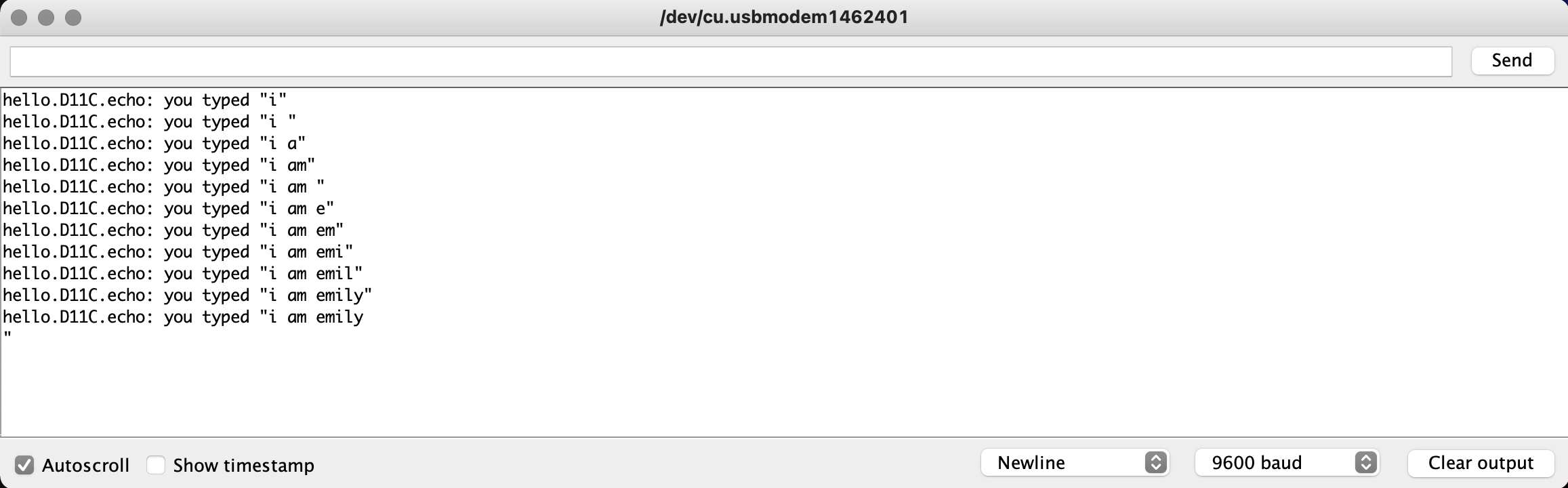
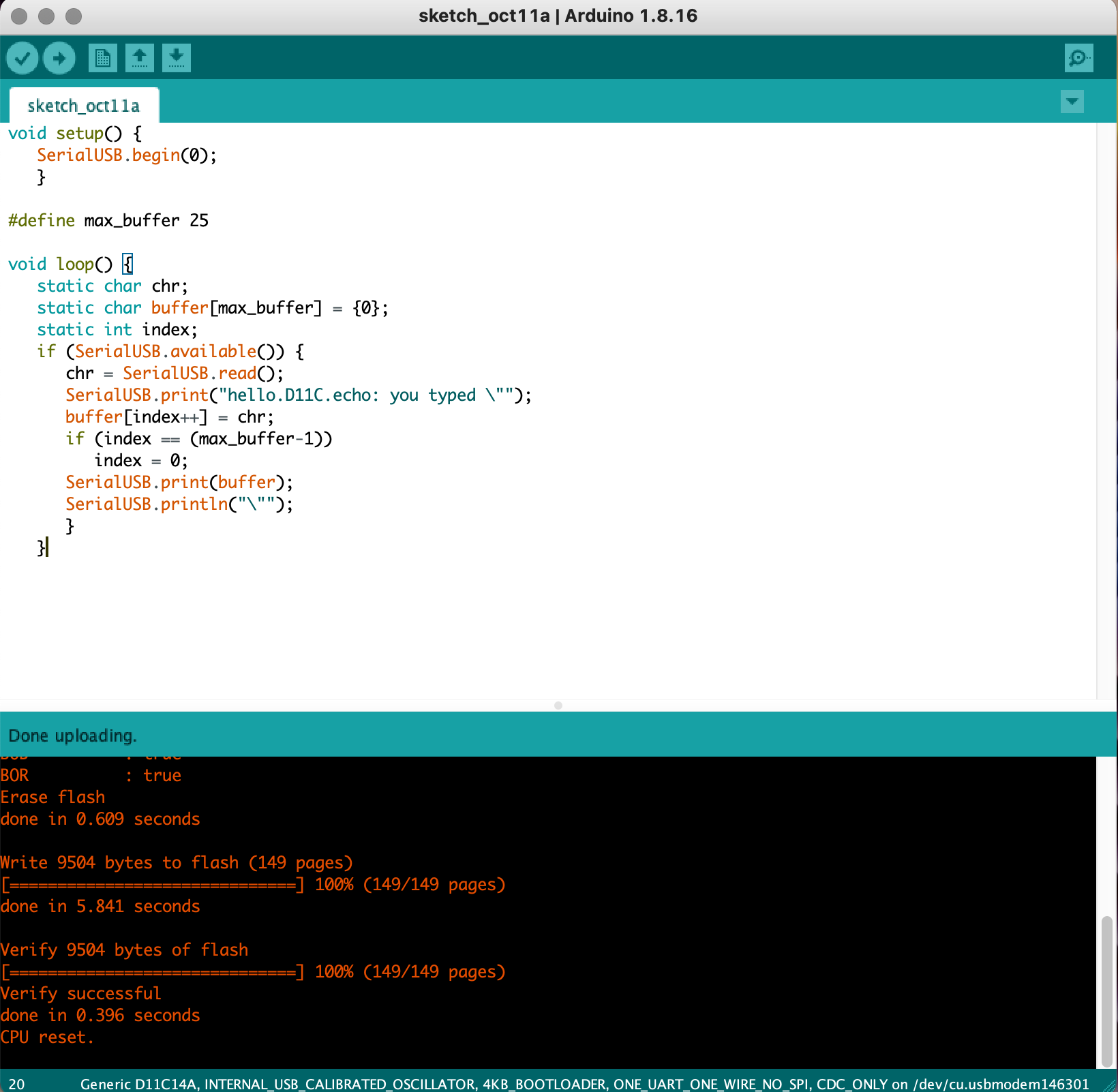
The code was successfully uploaded and it finally worked!! It types back any massage I typed into the box!!
03 Conclusion of the Week
//
Gained skills
Eagle, bootloader, oscilloscope, and more in-depth learning in milling and soldering
Thoughts and lessons learned
This week felt like a very heavy week to me. I felt more confident in electronics design than I did 2 weeks ago. Overall, the making process actually went pretty well. It was the understanding process that took very long to absorb. I didn't get a chance to test my ATtiny board this week but I might learn how to test that later.
In terms of mistakes, I made a lot of them this week. To conclude, here are several points that I felt like it is important to keep in mind before starting the making process:
1. Choose your tool carefully! KiCAD is super powerful, but the learning curve is greater. I felt eagle was more friendly to beginners.
2. Map out all of the needed components before routing and scheming them and check the directions of the components.
3. Set up the drc before routing!!