Input Devices
Learn about sensors and understand about input devices
01 Group Assignment
//
Probe an input device's analog levels and digital signals
The sensor I used for this week is digital, so there was nothing much to see. Thanks to Bo in our section who figured out the group assignment and here is what she did:
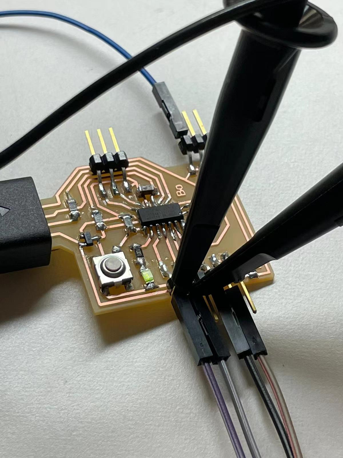
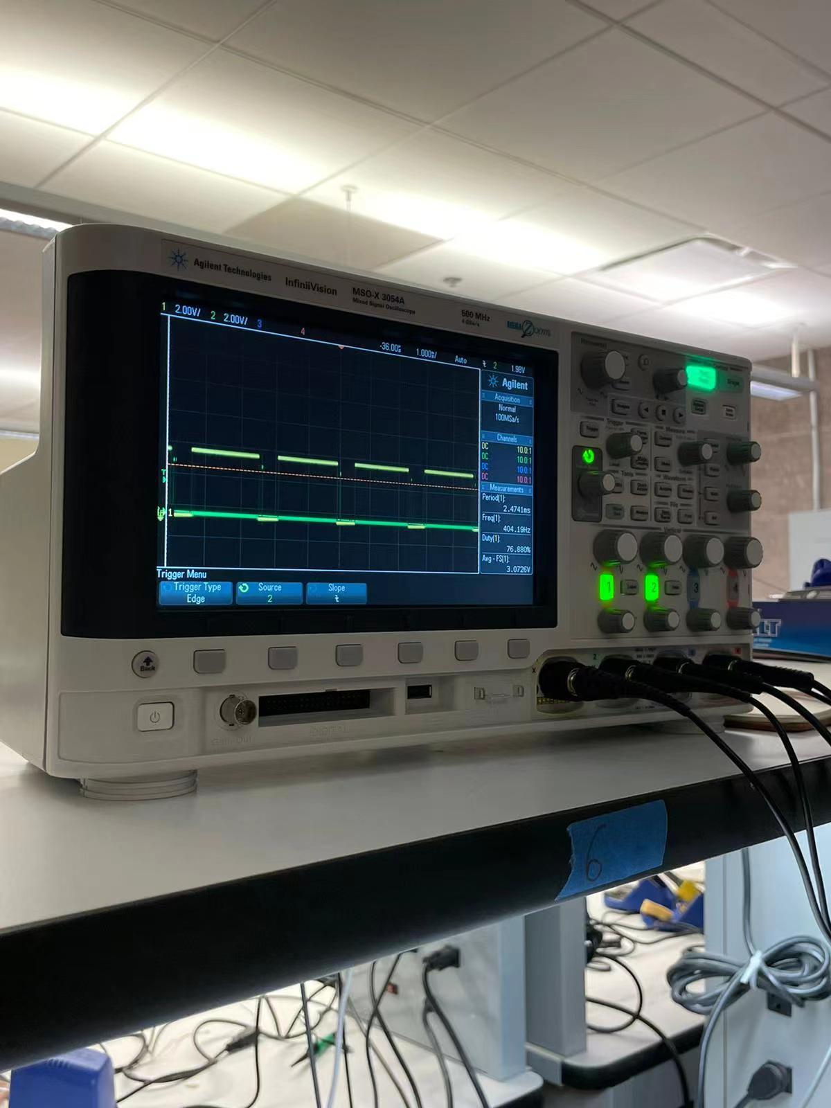
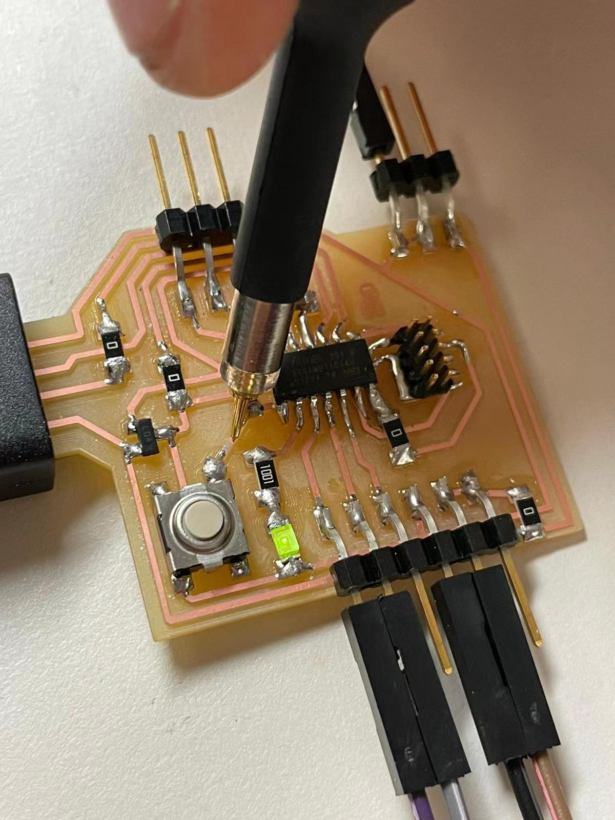
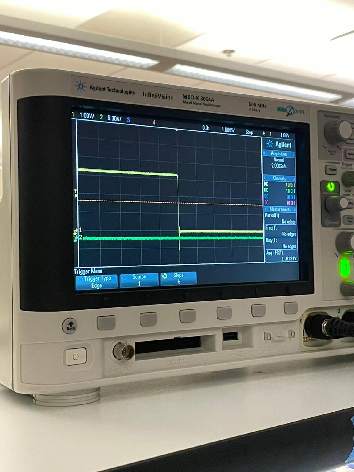
The first two images indicates the what will show up in the oscilloscope when probing a ultrasonic distance sensor. The last two images demonstate the button input, which looks very different from the analog because it only turns on and off.
02 Individual Assignment
//
Add a sensor to the microcontroller board
For this week, I decided to add a simple input device to my board and make a prototype for my final project. Since I might be controlling my project using switches, I decided to add two switches as the inputs and let them control a signle output. I started by laying out the scheme in eagle.
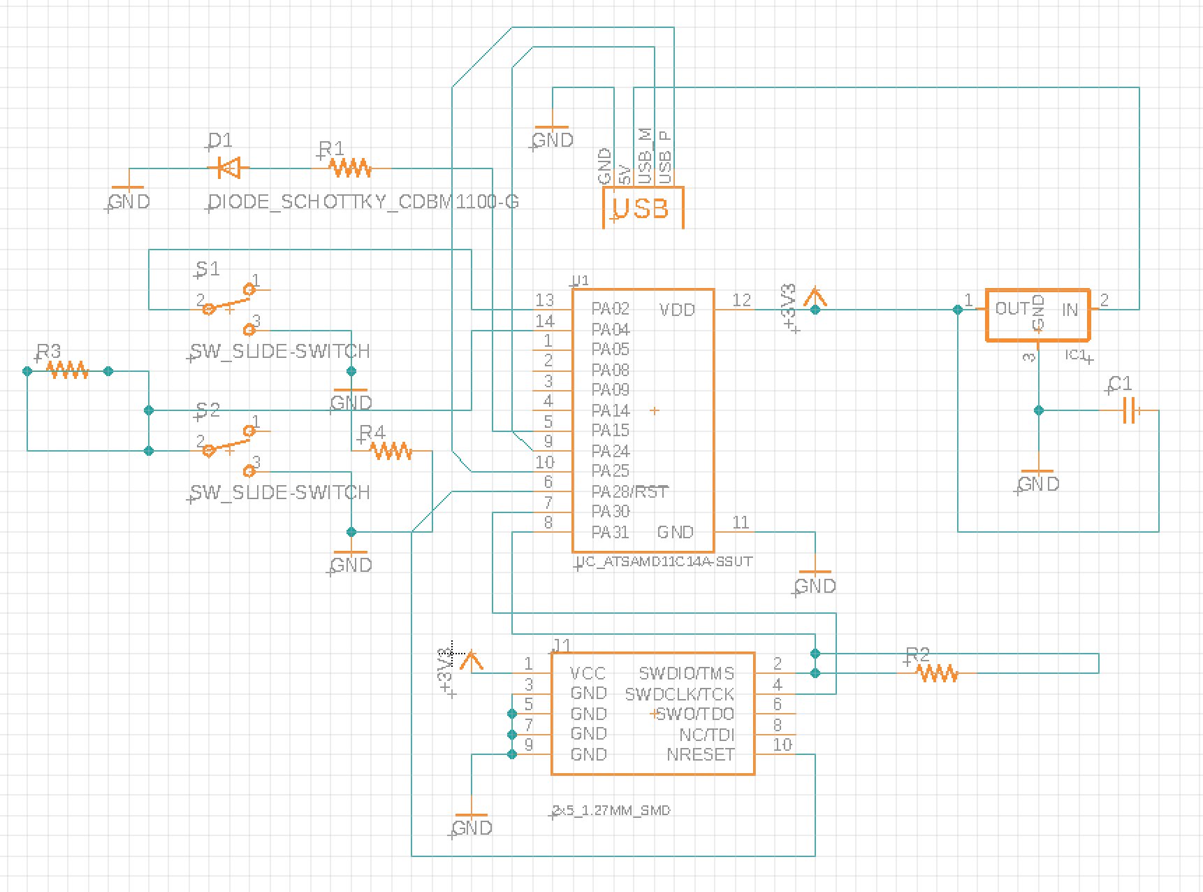
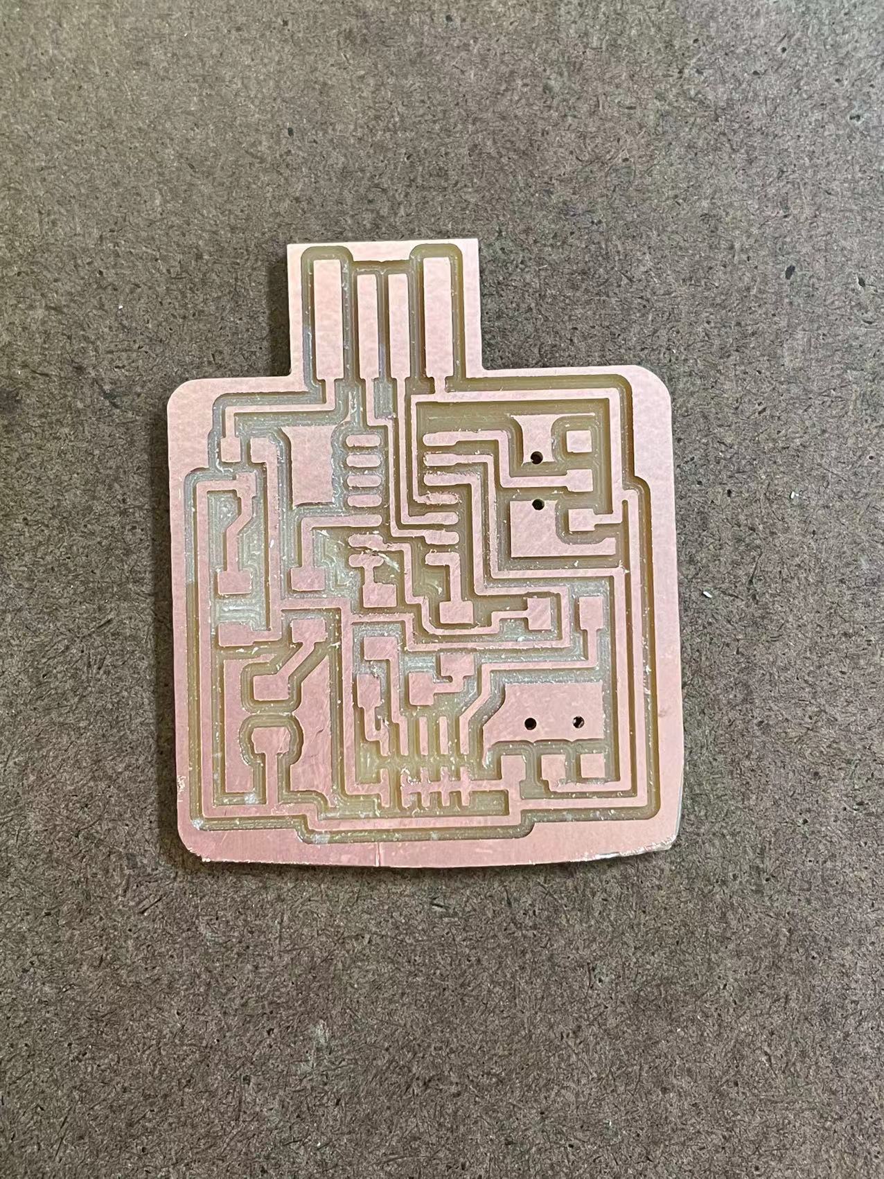
I routed the board in eagle and it did turns out very well. Some of the traces are getting too close, causing them sticking onto each other. However, I felt better using eagle now and the process of fixing this problem didn't take long.
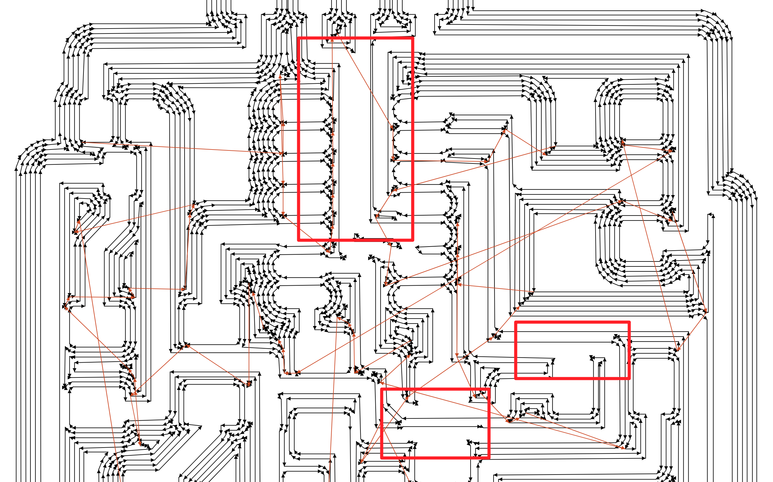
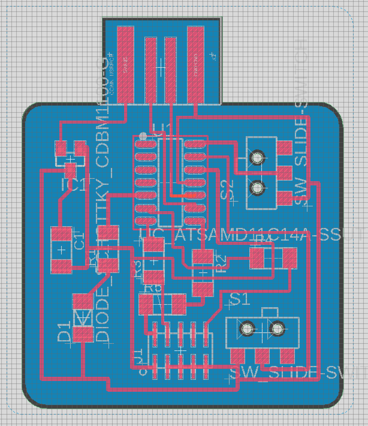
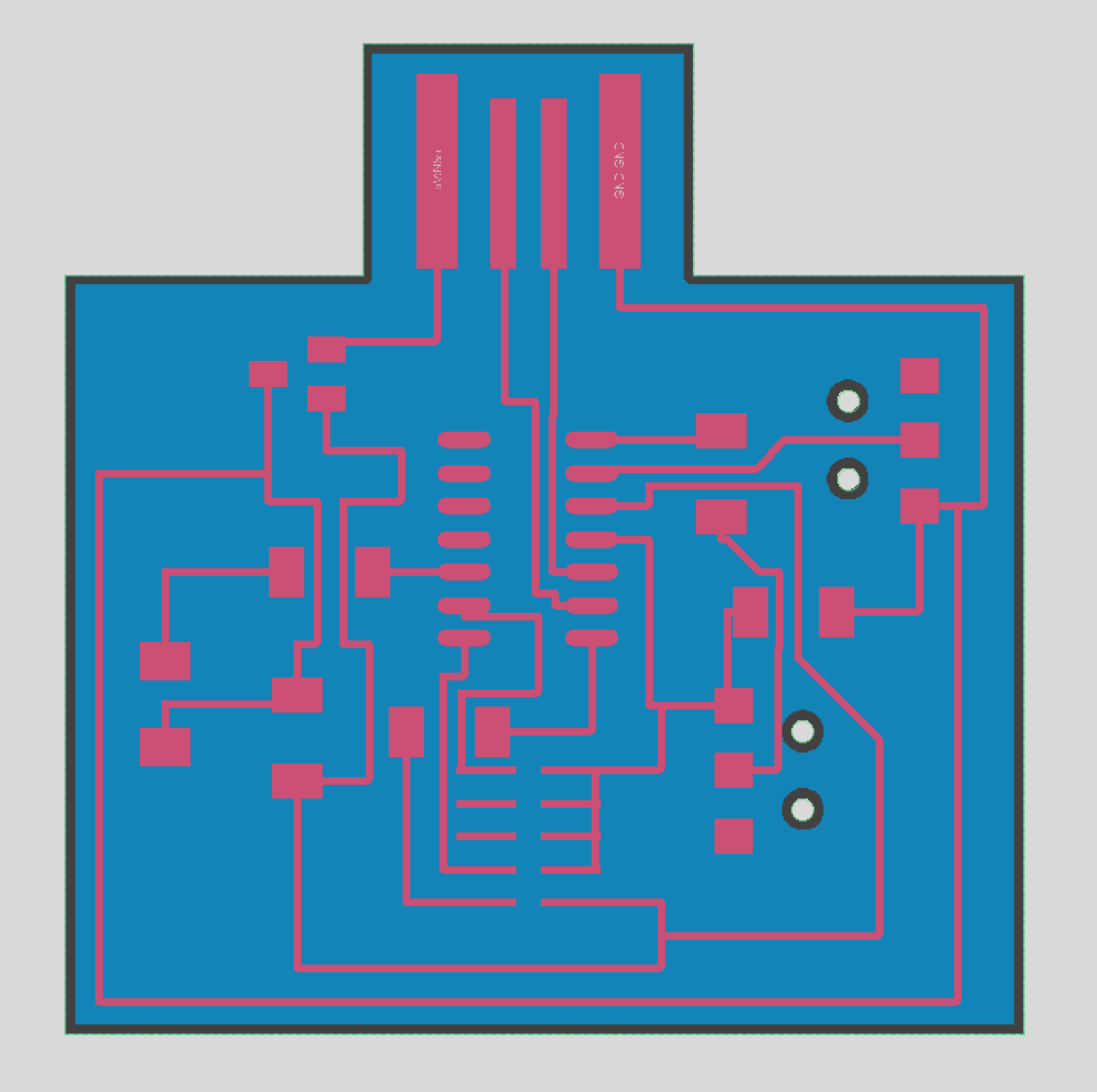
As you can see from above, the traces are sticking ontp each other. To fix this, I had to increase the dpi for the image up tp 2000 when I exported it, and put in 4000 in mods, which works out perfectly. I also rerouted the board just to make it more organized and tightly bonded.
//
Mill the board
I then used roland milling machine to do the making part. The process was simple and quick.
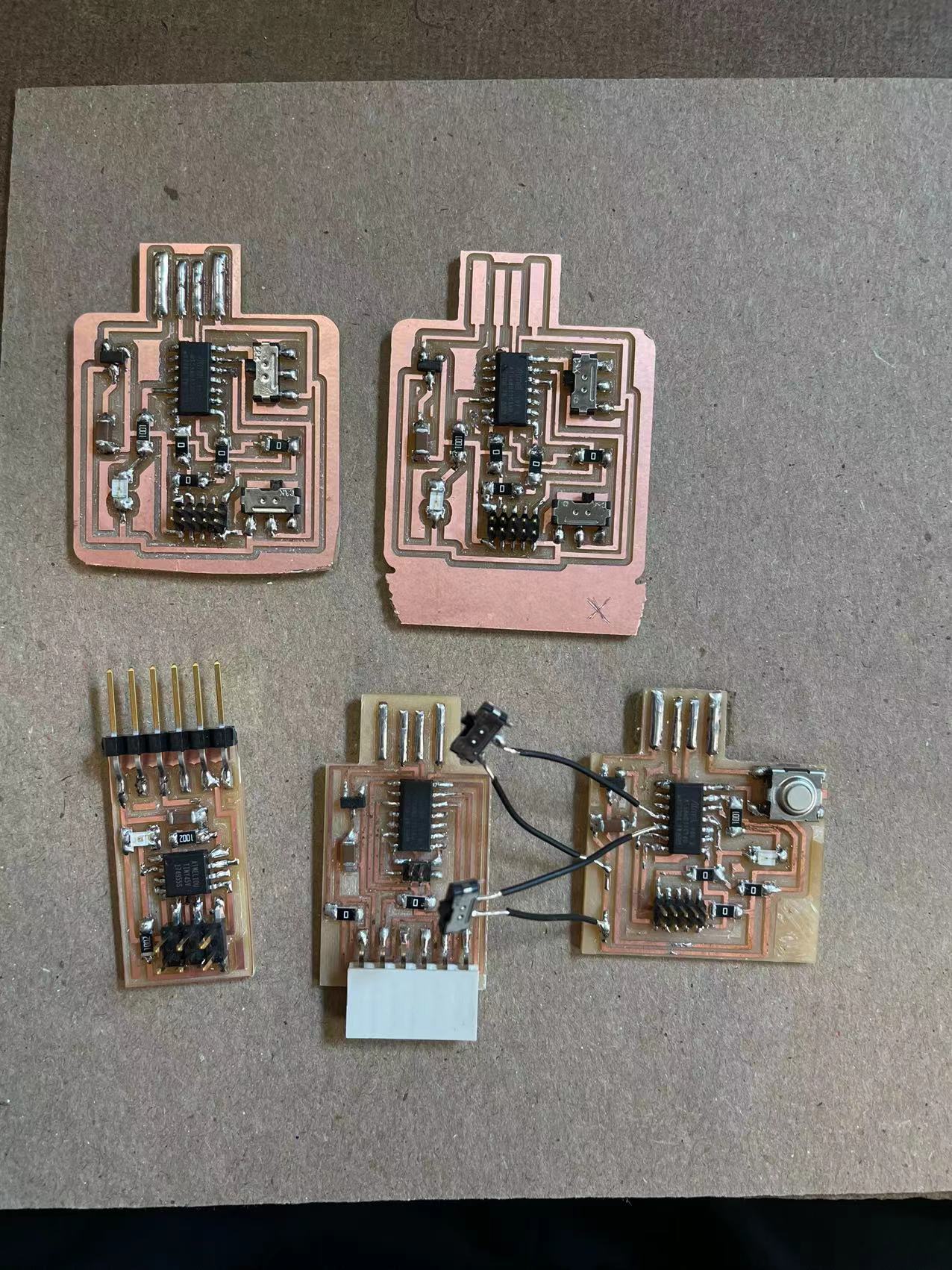
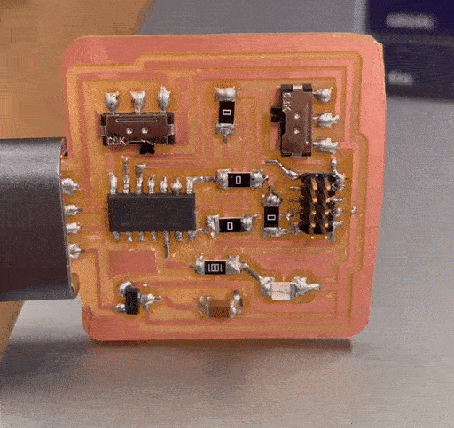
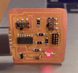
The board turns out fine. I stuffed it with some components similar to what I did in the electronics design week. I also wanted to explore some of the other sensors this week, but our shop seems out of color sensors and distance sensors.
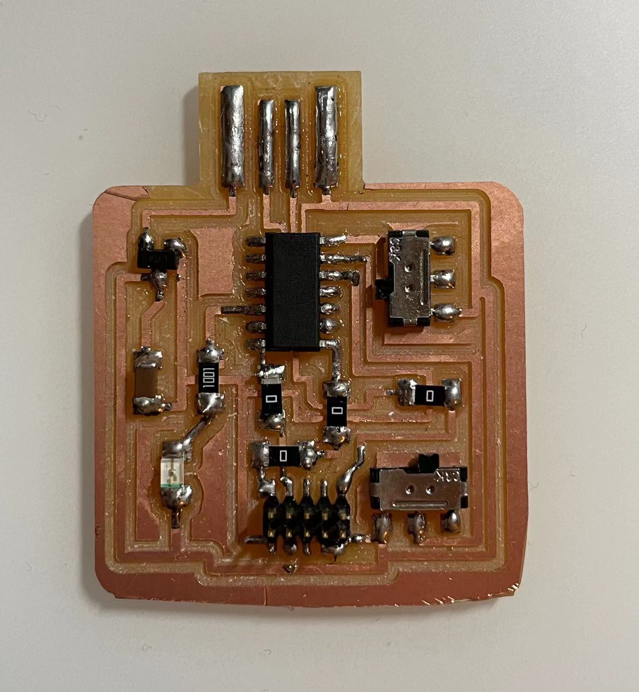
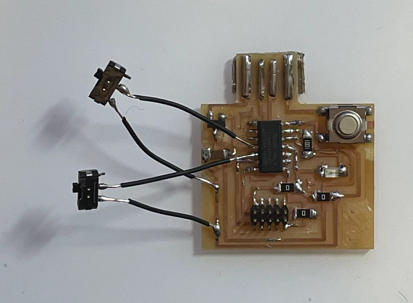
This is how they turned out! I also added two switches on the old board I made just to see if that would work or not. I attached the two legs to the switch to the GND and the digital ports separately.
//
Program the board
The hardest part for this week to me is the programming part, not the actual coding, but the process of sending the code to the board.
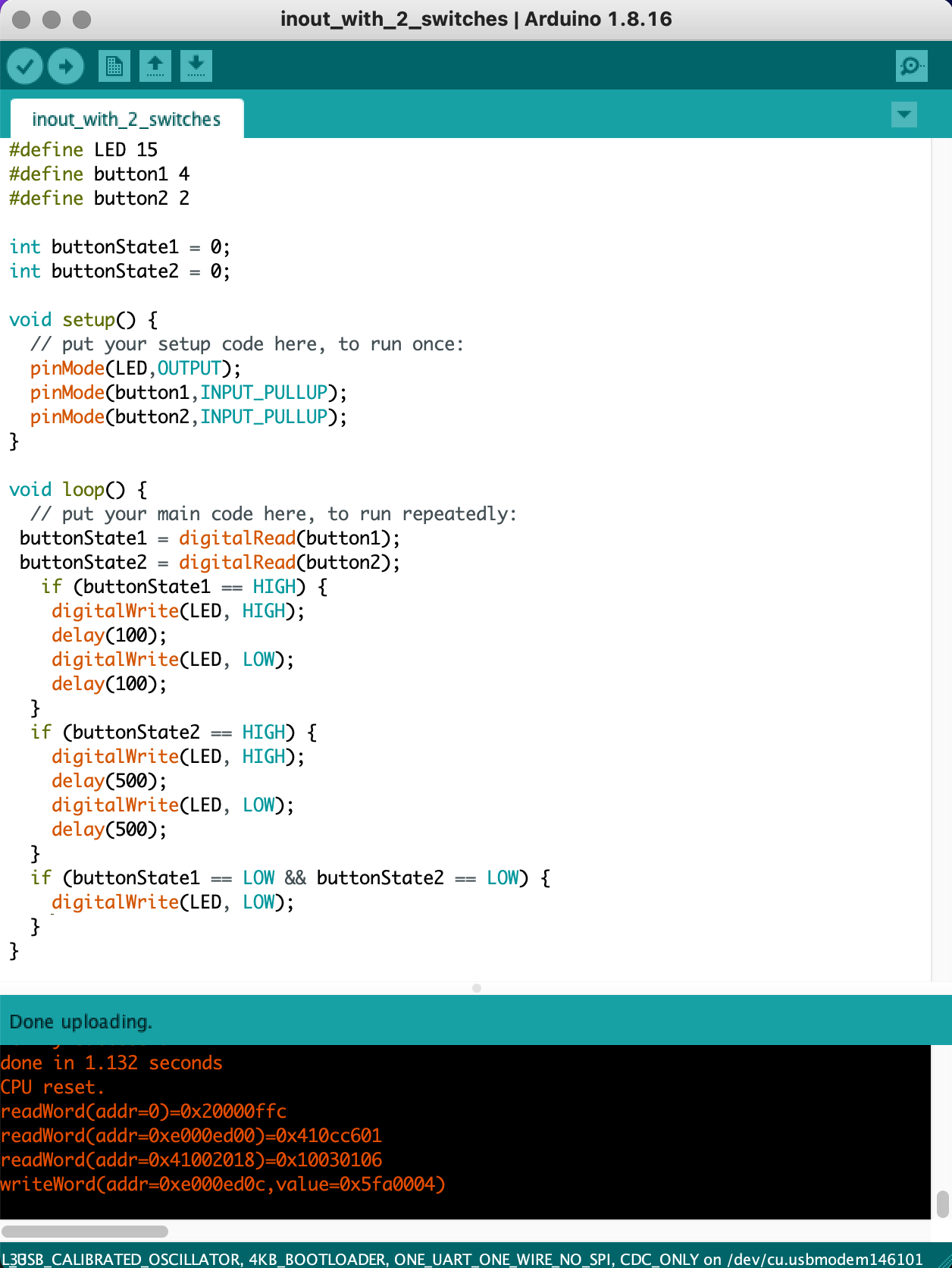
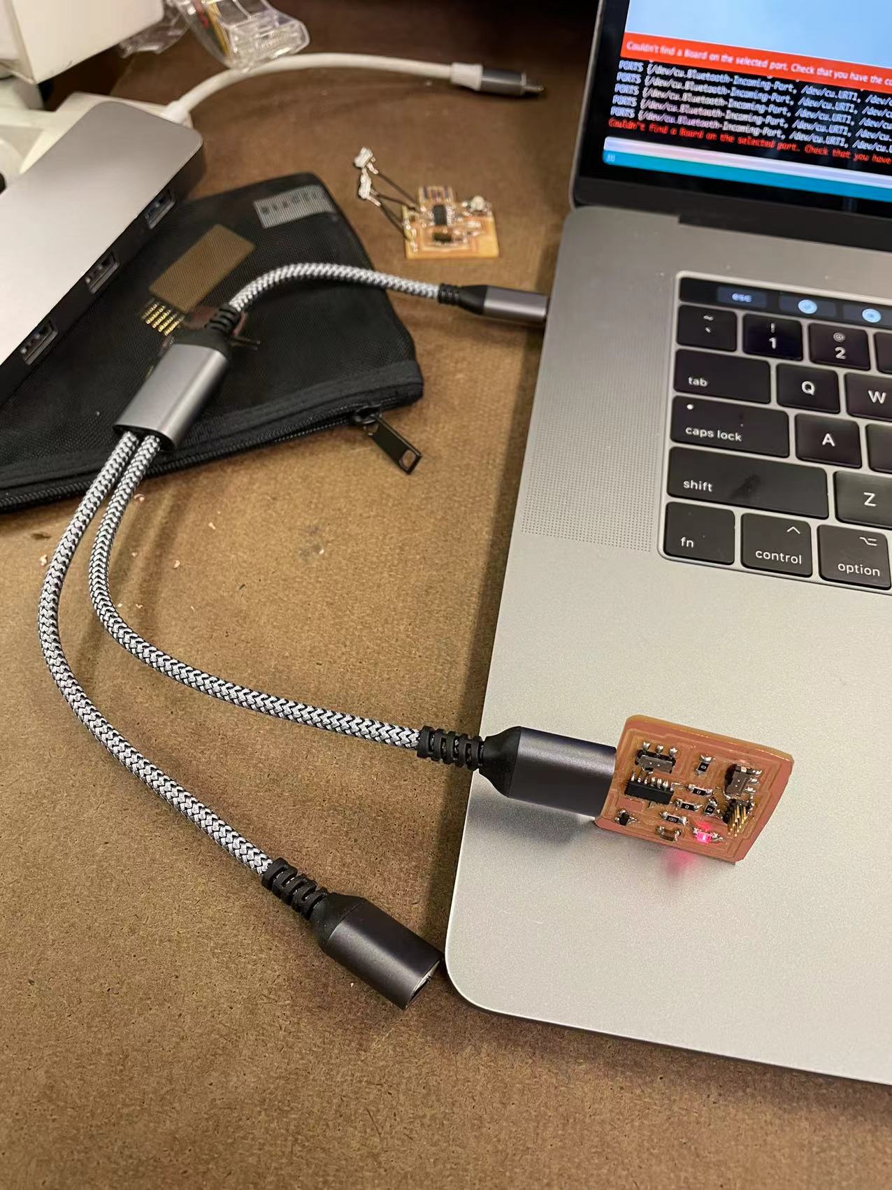
To start with, first thing that I encountered was that I was unable to upload the bootloader onto my new D11C board. There are two reasons that might have happened to it: 1. I didn't clean up the copper that was left over around the usb part, which can potentially leads to bad connection. 2. I flipped the 10 pin debugger upside down, which means the direction of the plug might have been wrong. (A BIG SHOUT OUT TO CALVIN WHO HELPED ME WITH FIGURING OUT THIS PROBLEM!!). The second problem that I encountered was the computer just wouldn't read my board. The bootloader was succesfully loaded and it seems to be working on the shop computer. It was quite frustrating figuring out why my computer just wouldn't read it. Fortunately, it turns out that using a extensuion usb cable would solve this problem perfectly. I am not sure if this is a mac thing, but plugging it into a convertor is not a very stable way to read the board.
It finally worked!!! I programed the board so that when switch 1 was flipped, the red LED would blink at rate of 100, and when the switch 2 is on, the LED would blick at rate of 500.
03 Conclusion of the Week
//
Gained skills
Understanding of how simple sensors work, reinforcement on milling and designing electronis
Thoughts and lessons learned
This week was a really good week for me to review what we learned in the previous weeks. I had the opportunity to refresh my memory and got a good understanding what my final project would look like.
Here are some of the lessons learned that I think would be beneficial to know before starting this week:
1. Double check to see if there are any shortcuts on the board before soldering.
2. Get to know what kinds of sensors are avalible in the shop so that you don't have to wait or waste any materials and time making something that we don't have.
3. If the ports on your computer does not recognize your board, try using an extension cable.