Output Devices
Learn about output devices such as LEDs, motors, displays, and speakers...
01 Group Assignment
//
Measure the power consumption of an output device
Our TA Anthony showed me several ways to measure the current and output power. I decided to go with the multimeter way. I powered the board and touched the GND and power line with the multimeter tips.
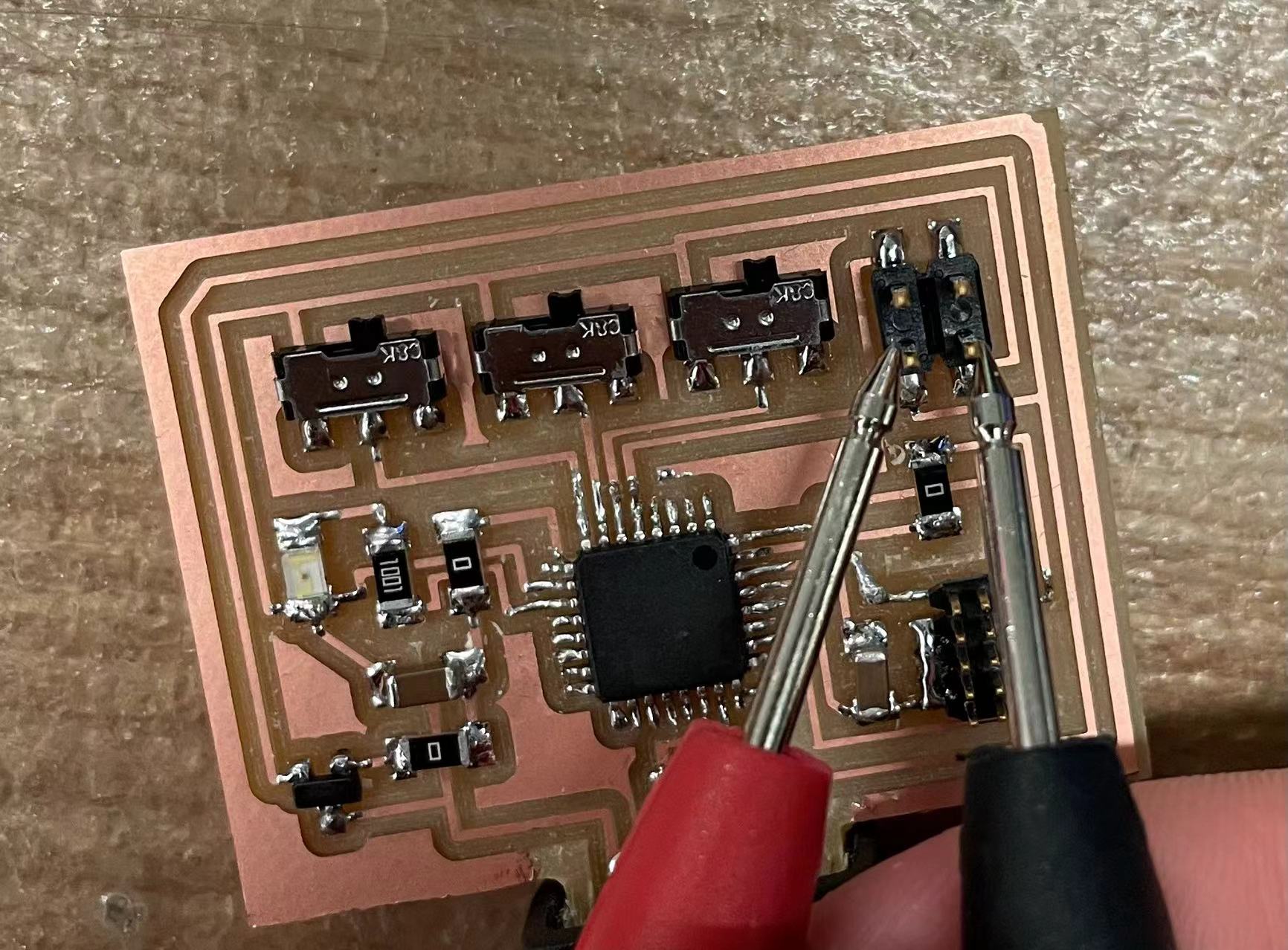
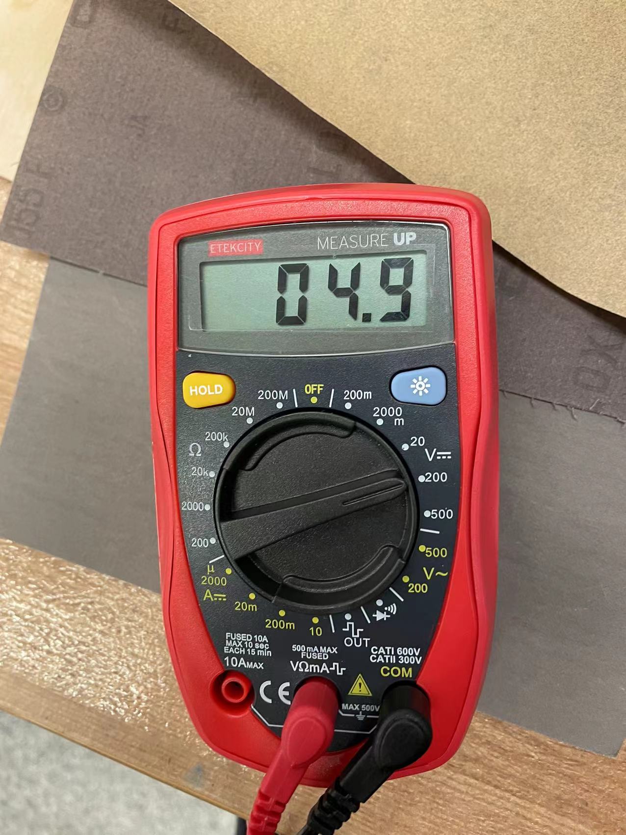
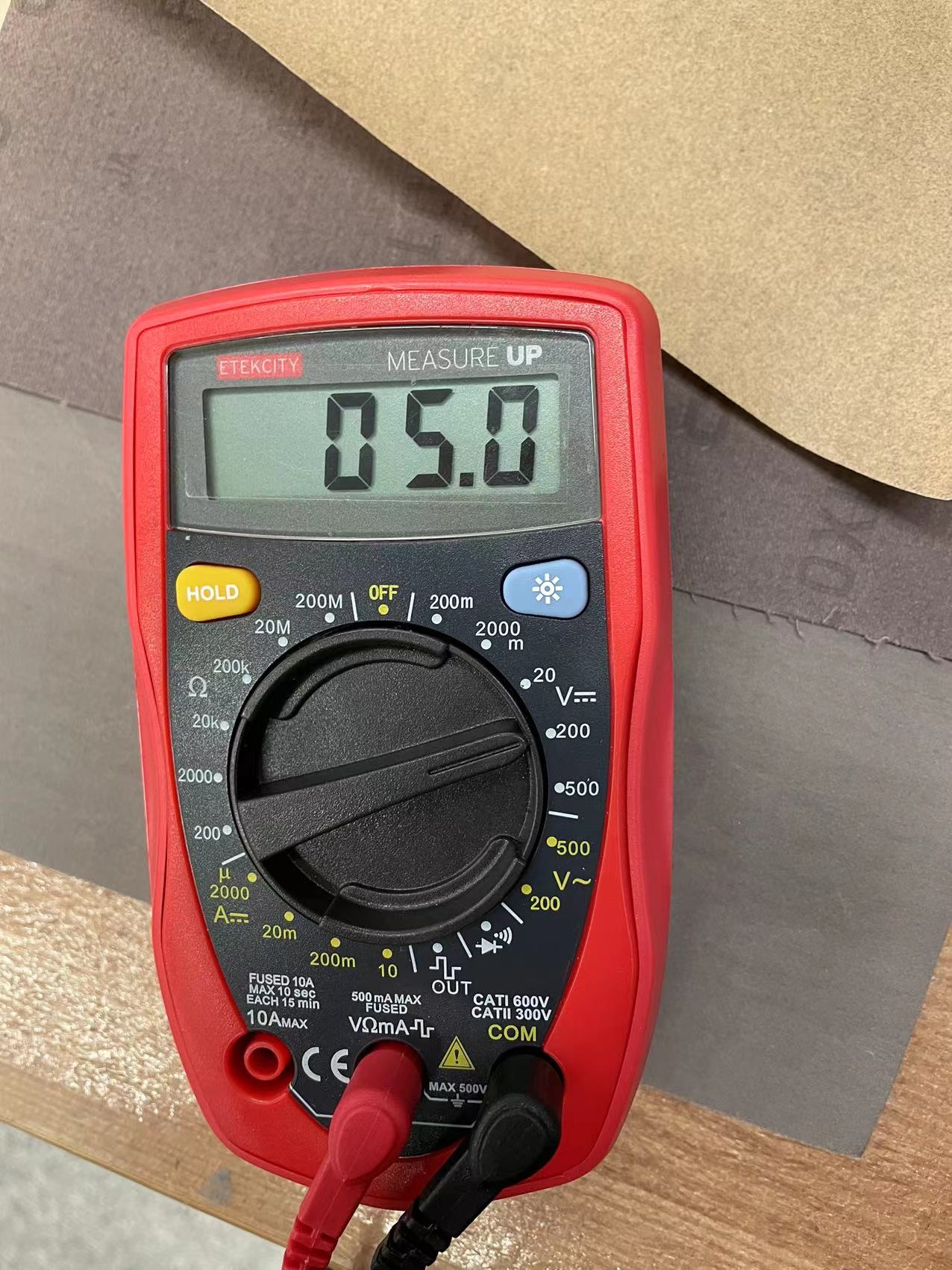
The reading indicates that my output device will receive 5V of power, which is what the neopixels will need to light up. You can see the measurement is not very consistent, sometimes it goes down to 4.9. This is not a big issue here as long as it stay close to 5V.
02 Individual Assignment
//
Create an output device
For this week, I decided make a prototype for my final project. The output for my final project will be a 10 by 10 neopixel LED matrix, so I decided to make a 6 by 6 matrix as a prototype. I started making the board in rhino and cutted it out with laser-cutter.
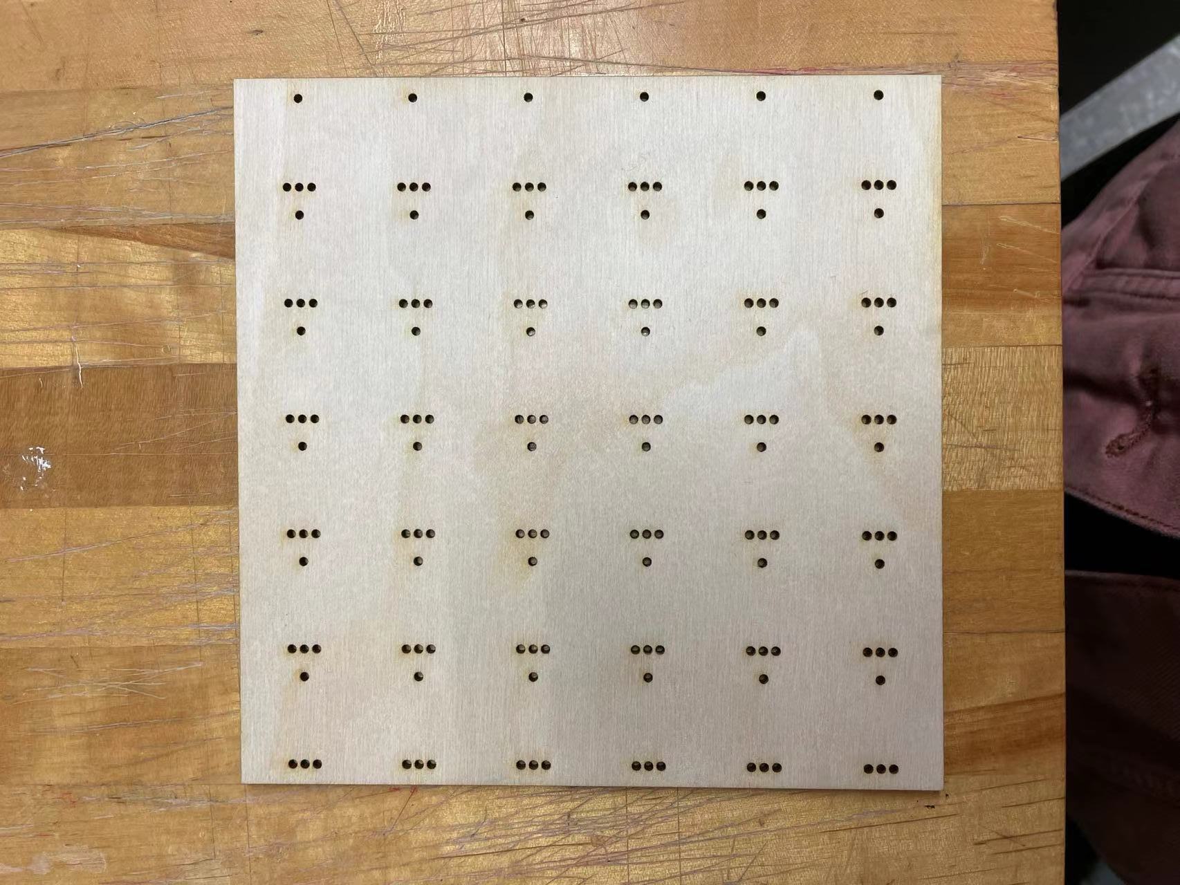
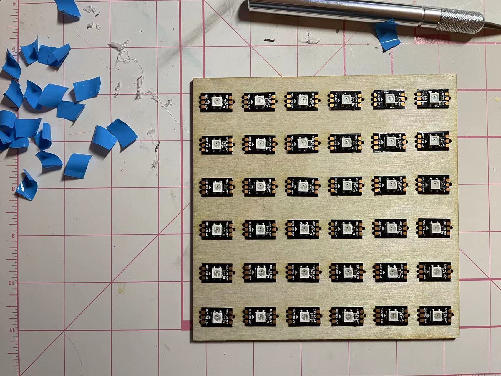
The board on the left is what it looks like after laser cutting. Each of the holes are used for soldering each individual LED to the ground and power wire. I taped down each of the LED onto the board as shown in the right.
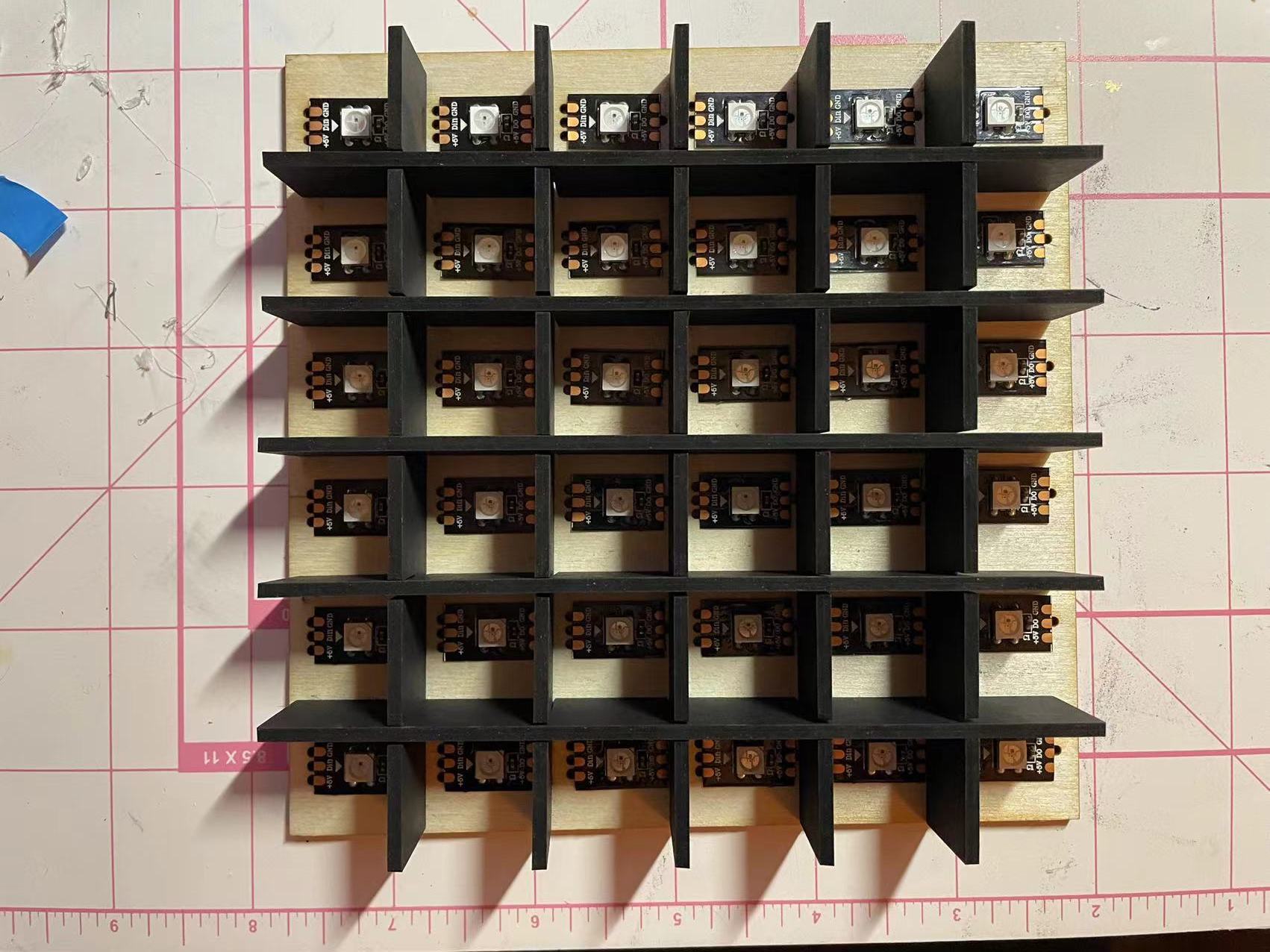
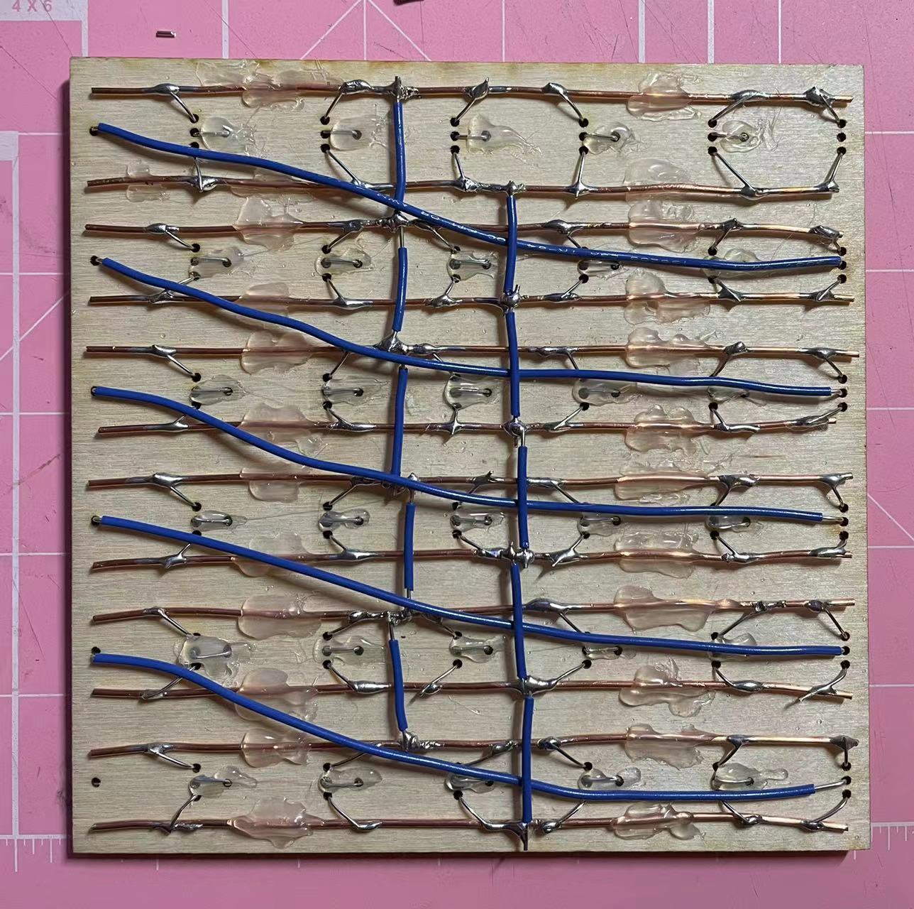
I also made a grid for the LED system so that each of them will lit up uniformly in their own space. I soldered the back side.There are two main wires going across the board to connect the ground and power into two main traces. More detailed description can be found in the final project page.
//
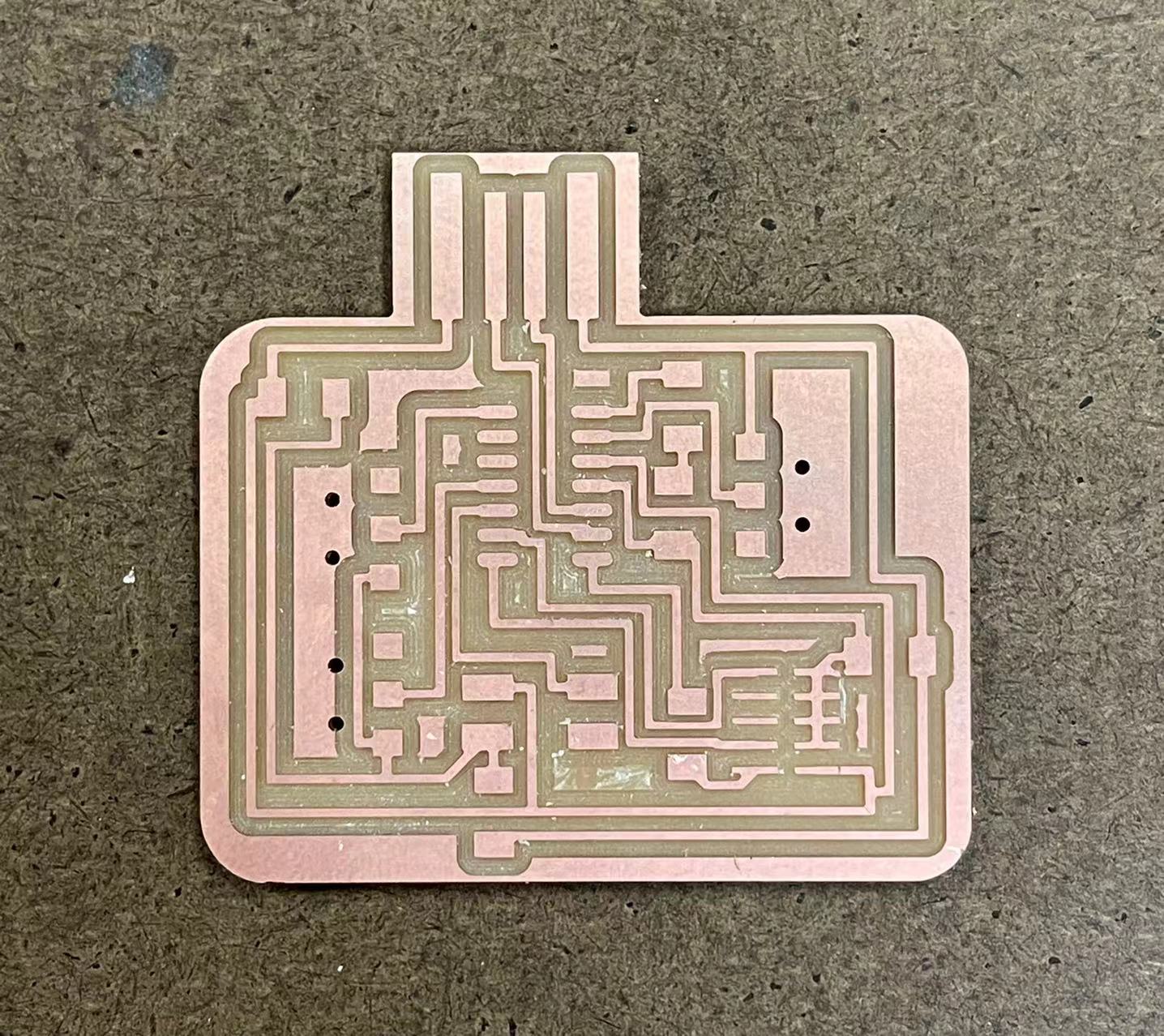
Design the output microcontroller board
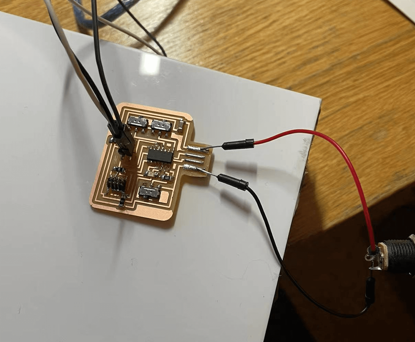
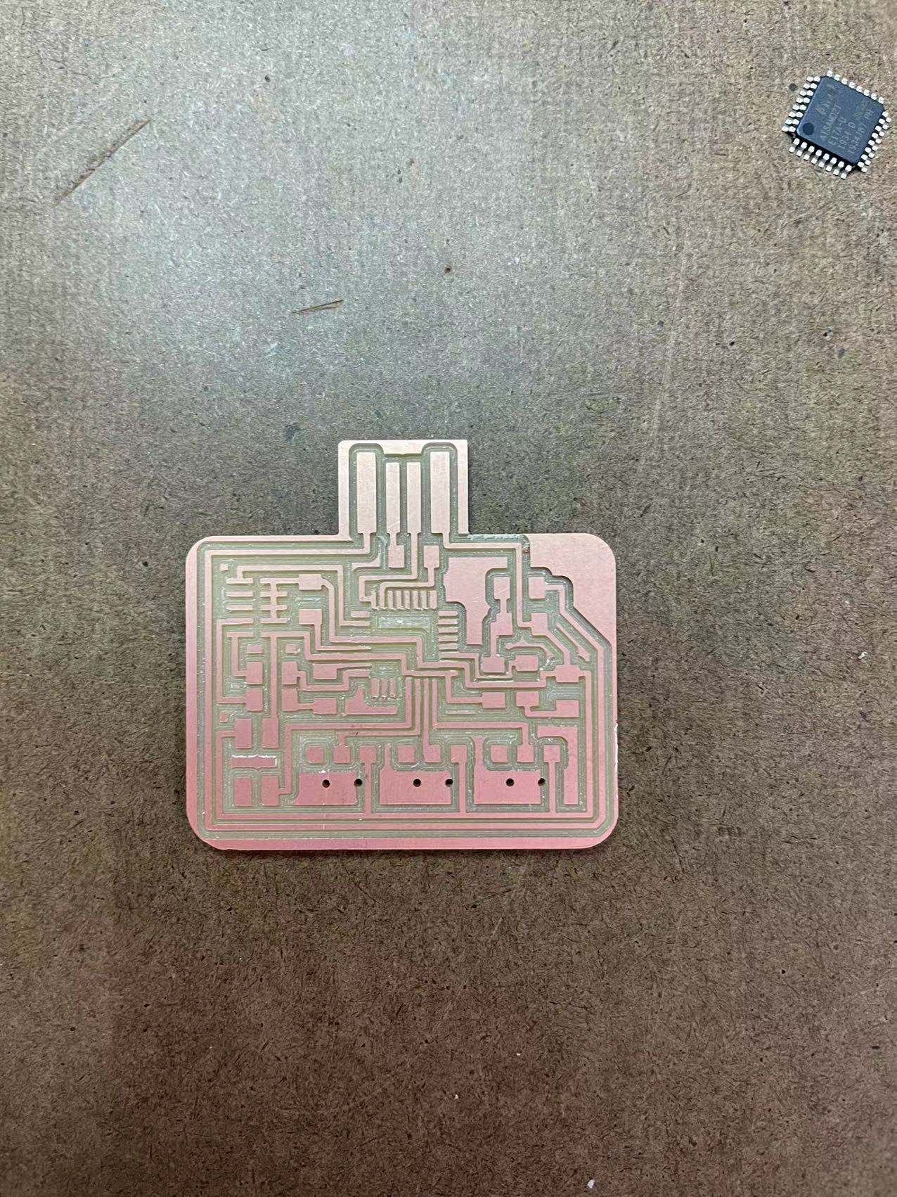
I designed the board in eagle and milled it in roland machine. A four pin connector is used to connect my prototype to the microcontroller.
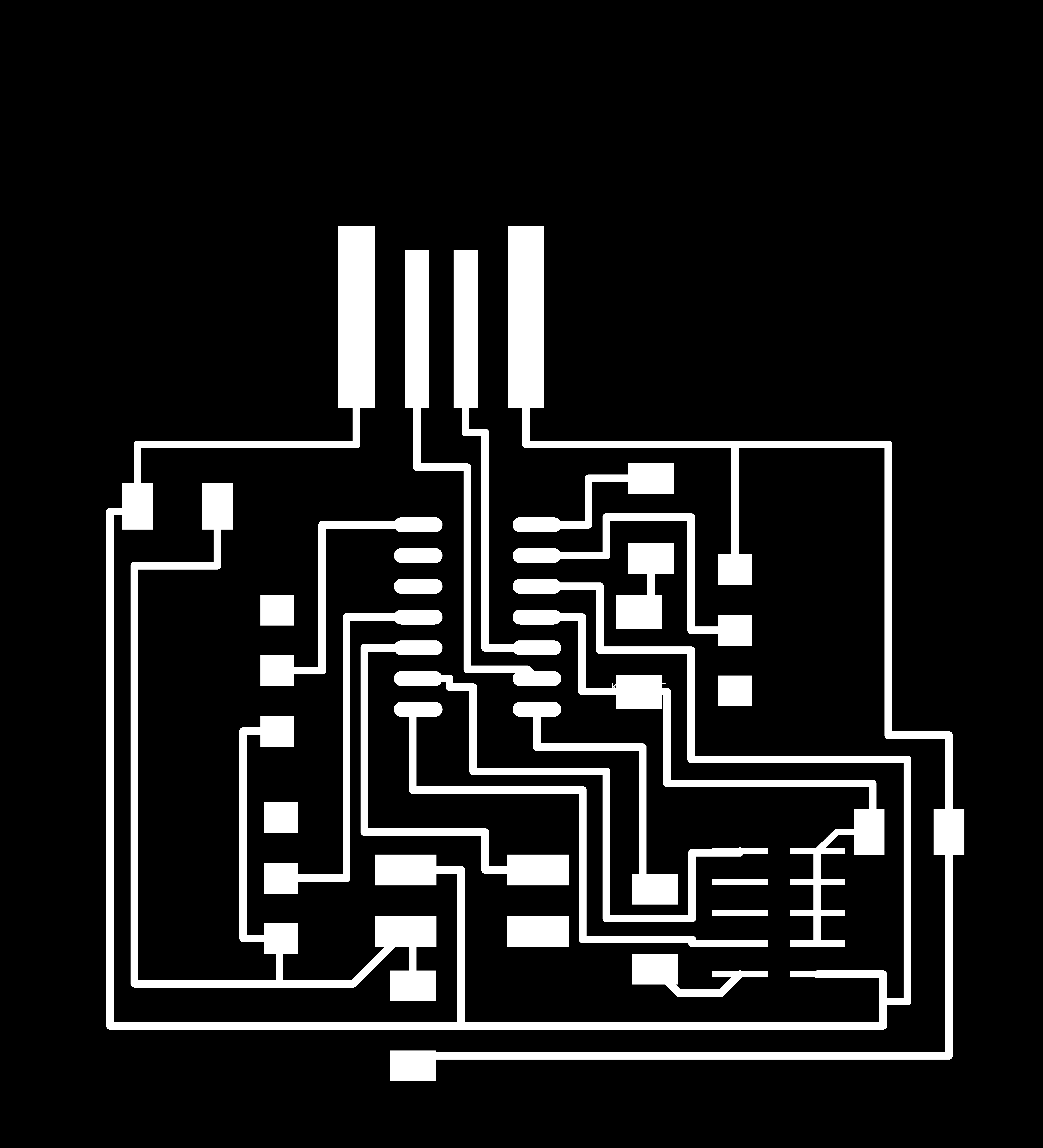
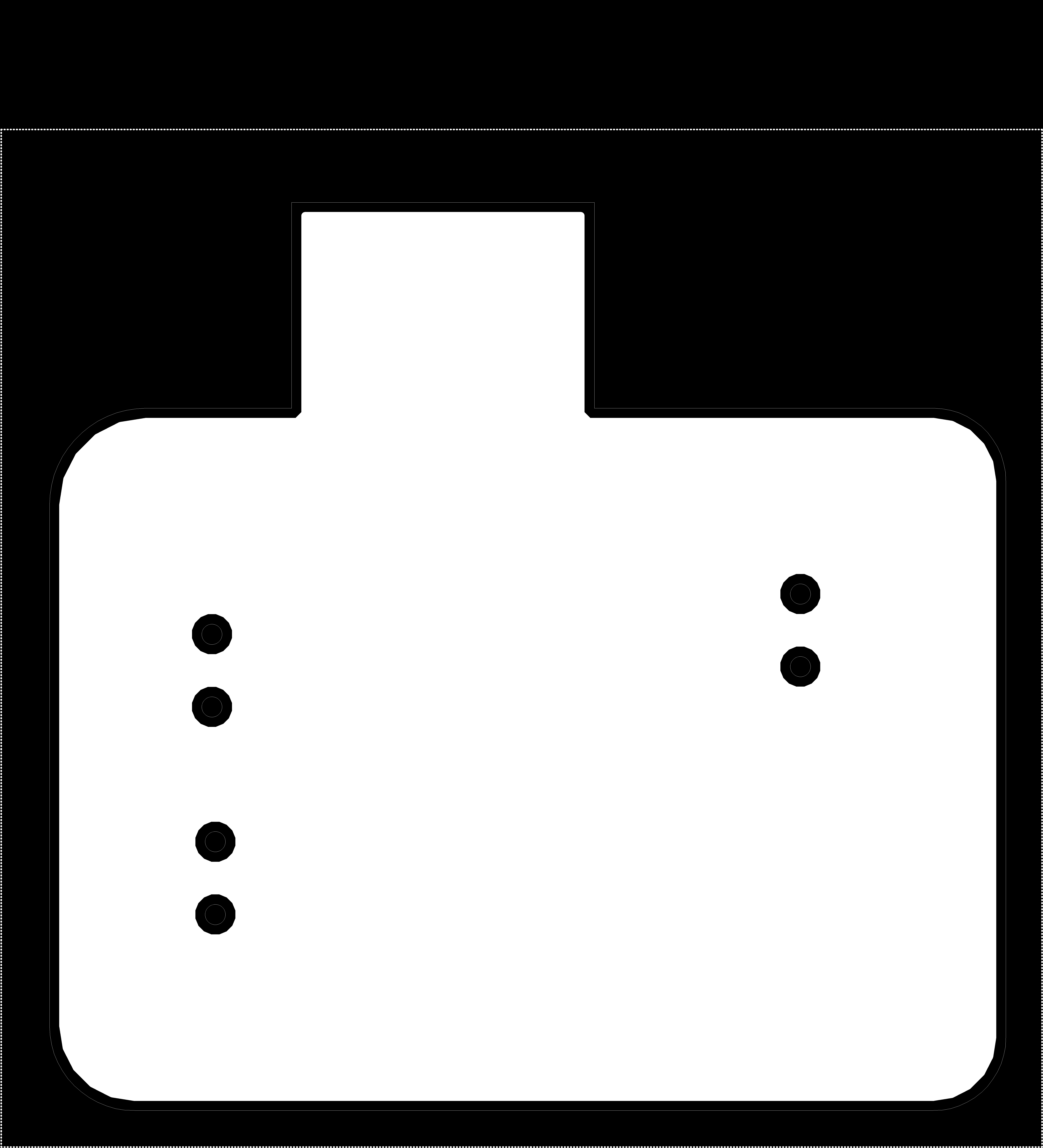
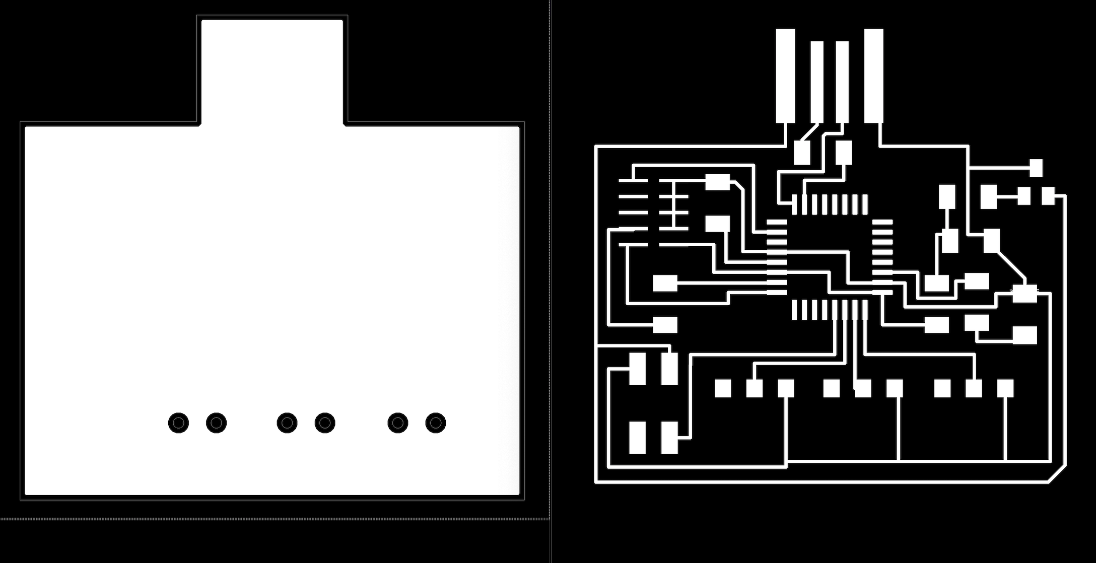
I also added three switches to the board as the input so that everytime I switch it the pattern on the LED board would be different. Here are the traces for my board.
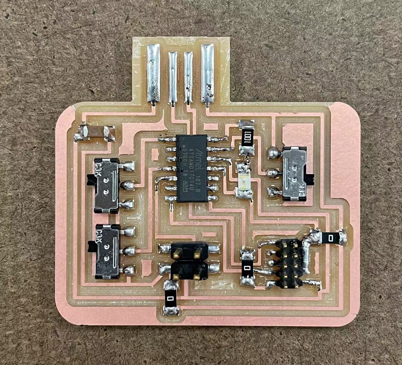
This is how they turned out! The board came out nicely and soldering was also shiny. I successfully bootloaded the board and started the programming process. This process is getting easier for me now and I am pretty confident in making and designing boards again!
//
Program the board
I started program the board using neopixel library code in arduino. The code was succesfully uploaded but it is not showing up on the LED panel. I suspect that would be a power and current problem. (UPDATE: It was a arduino library issue. I used the adafruit_neopixel library and it would only work on certain types of microcontrollers. Anthony helped me with finding the correct microcontroller to use, which is D21E.)

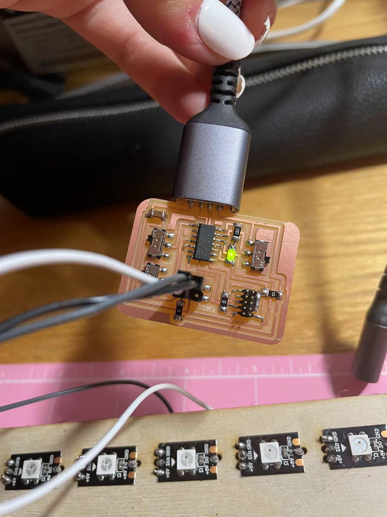
I connected the power, ground, and port to the connectors like the settings on the right.
I also tried to connect the board's power trace to an external power supply, but it still would not show up. So I decided to program it with arduino uno first and then figure it out in office hour.
It worked with arduino uno! The result looks good but I will need to figure out how to code it with a d11c microcontroller. The right gif demonstrates a code from FastLED library.
//
Update with the board
I made a new board with the D21E microcontroller. Most of the details and components are still the same with the D11C board.
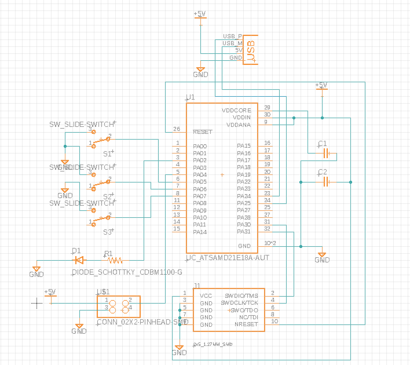
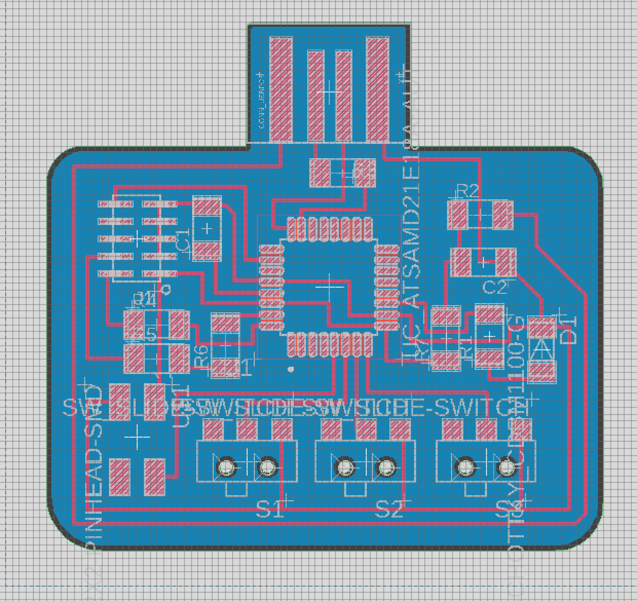
These are the scheme and board design for the D21E microcontroller.
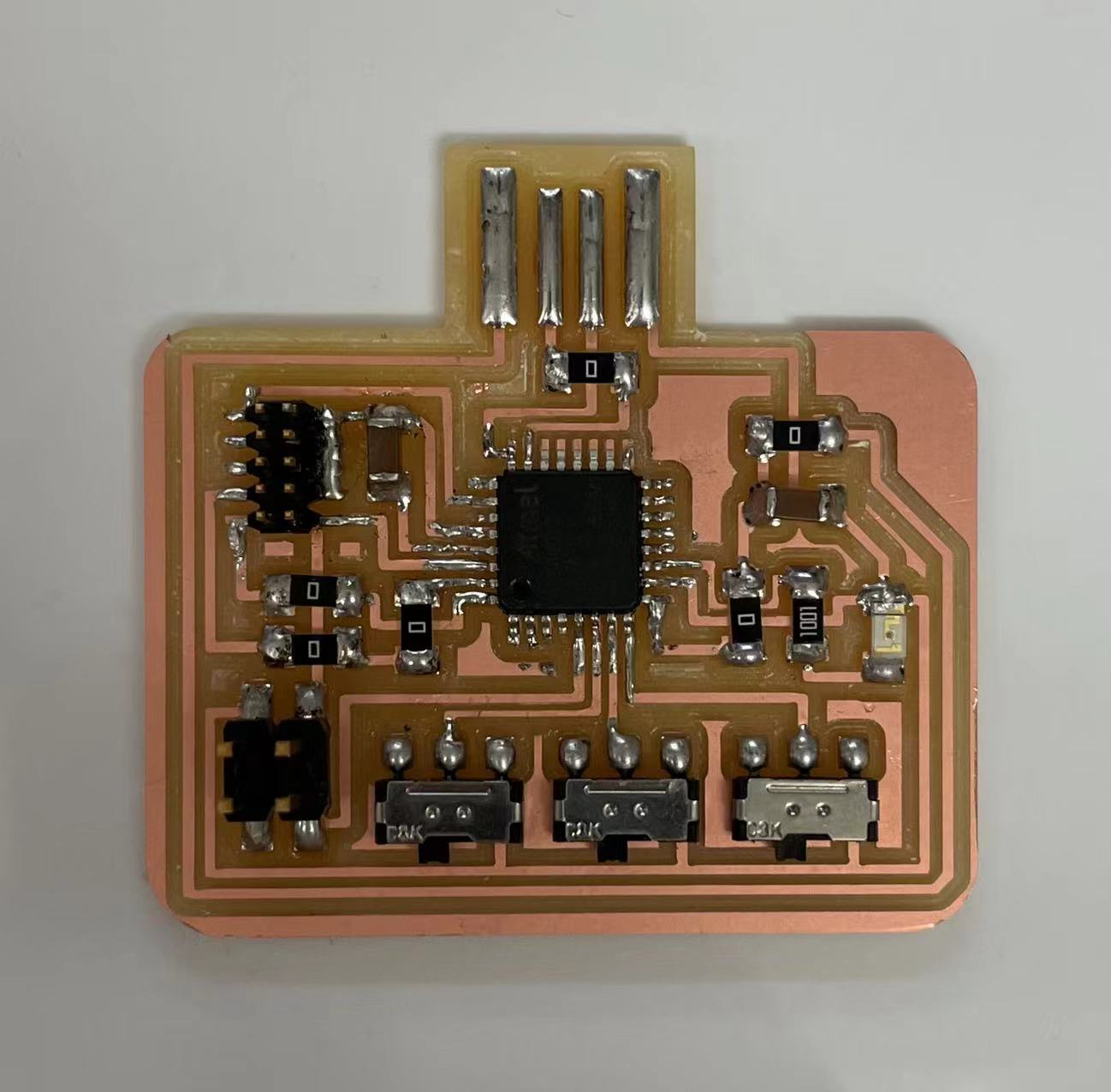
These are the stuffed version of the board. Unfortuately we were unable to bootload this one because I didn't add a voltage regulator in there. Microcontrollers can only take on 3.3V instead of 5V. However, it was suprising that I got the LED to blink on the old board with the wrong voltage, I shouldn't be able to even bootload it. I am going to make a new board with the voltage regulator and see if that could work or not.
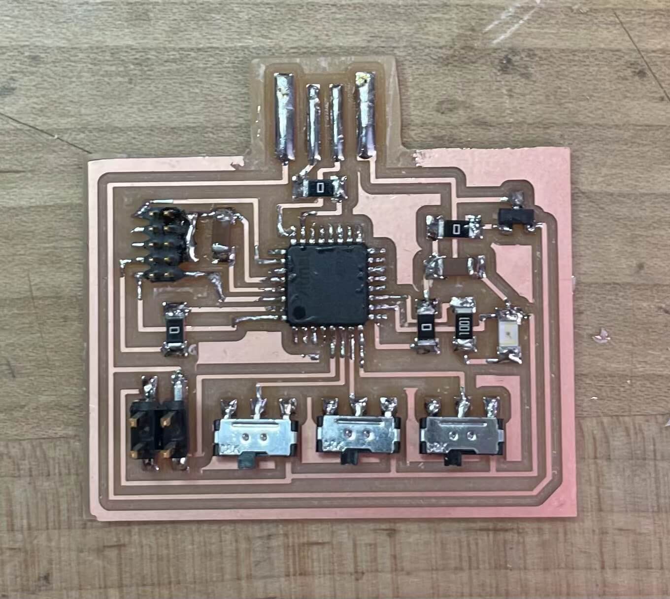
I redrew the board and fixed the voltage and microcontroller board issues. It was hard for me to solder the D21E at first, but after some practice it went smoothly. (Tip: try to use a finer tip soldering iron for smaller parts.)
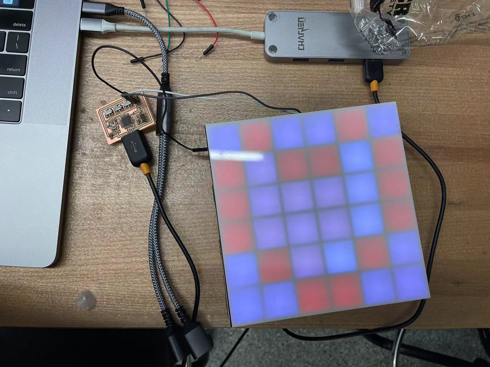
It finally worked! I made three board this week and learned a lot from my mistakes. I can now focus on the software end make some patterns out of this canvas.
03 Conclusion of the Week
//
Gained skills
Protype making, more practice on board design, coding output devices.
Thoughts and lessons learned
This week was a really good week for me make my prototype because my final project depends heavily on LED outputs. I found it really interesting to program a variety of patterns with arduino. I will also use processing to do image pixel recognization and send that information to the board next week.