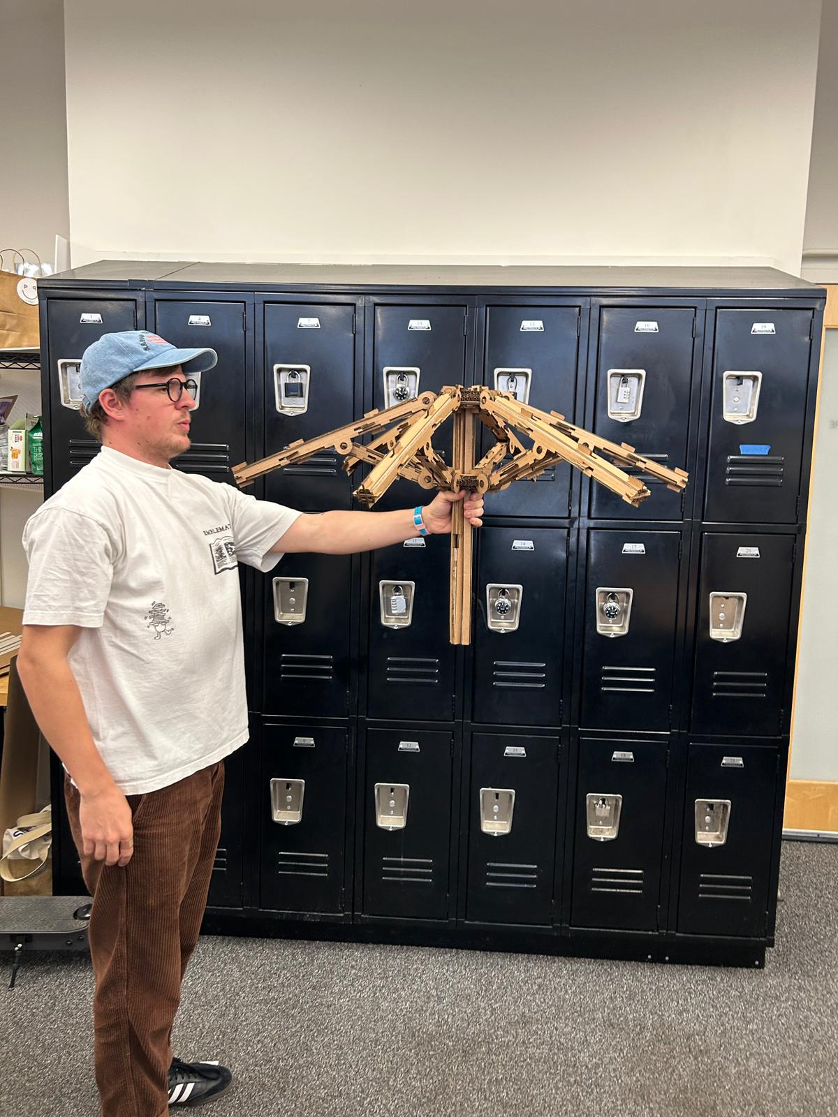
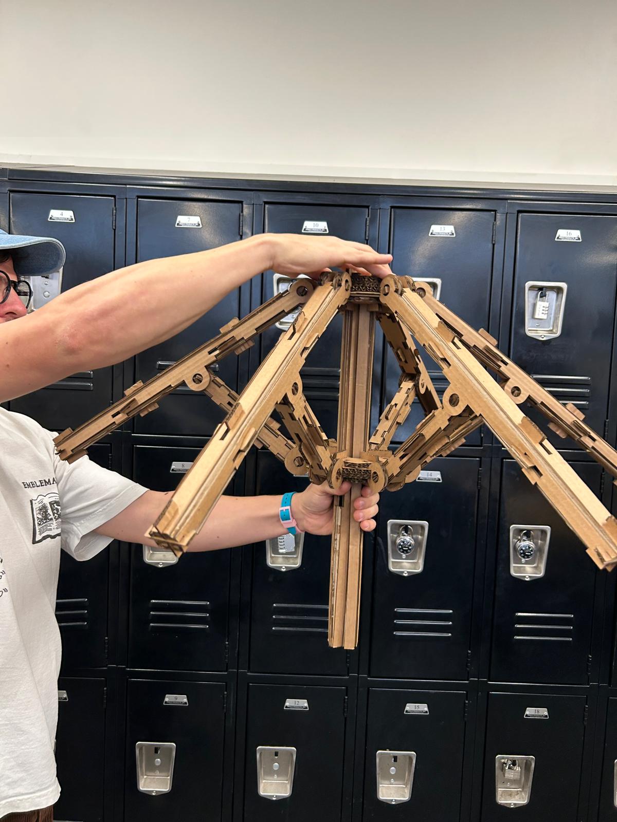
#1 /6 umbrella
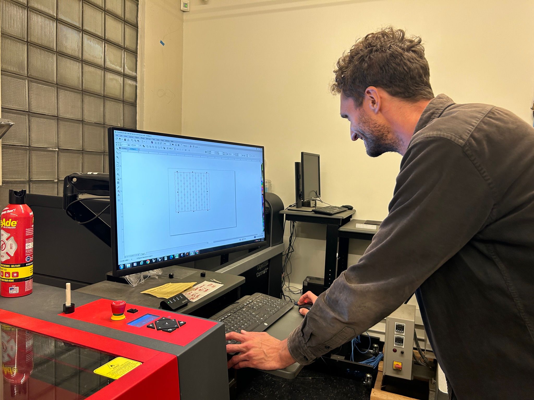
Getting started with the laser cutting week, I worked together with Niklas Hageman to getting to know the machines. We drew some of our work in Rhino and exported the lines to .dxf files. In the shop on the 3rd floor of N51 we got to use their Universal Laser Systems machine. To send a job to a uls, in many shops one can print straight out of Rhino using the print function, but in this specific shop, they wanted everyone to open the line drawings as .dxf in a software CorelDraw. We have to make sure that all our lines are using the thickness "hairline" in order for the usl software to identify them as vectors instead of raster files. From there, we double check that the colors of all the lines we want to cut with the same settings are the same (if not specified already with the layer colors in Rhino before exportig), and make sure that the colors are absolute black, red, blue, or green (these are the colors that the usl software can identify and use different settings on - for engravig or cutting, vector or raster).
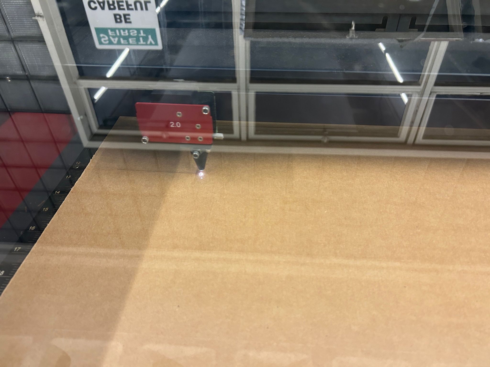
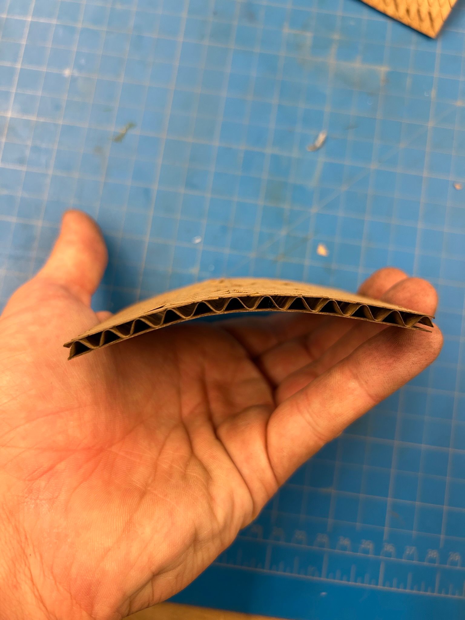
Before starting to cut, we have to make sure the shops vacuum is on, to pull the smoke out of the machine. We also have to set the z-height of our material manually in the z-axis settings of the machine, using one of the focusing calibration sticks. We realized that thin material (under 1/8") should be focused using this stick to the top of the material. For anything that is thicker, we tried to first focus the laser to the top of the surface and then make sure that it is focused to the middle of the material. the reason for this is that the laser beam is focused as a cone, and when you cut a thicker stock material you might actually see the cut in cross section to be not perfectly vertical. Since we are using corregated cardboard, this does not matter all that much, but if we had 1/4" acrylic, we would be able to minimize the slanted kerf by focusing the laser in the center of the material.
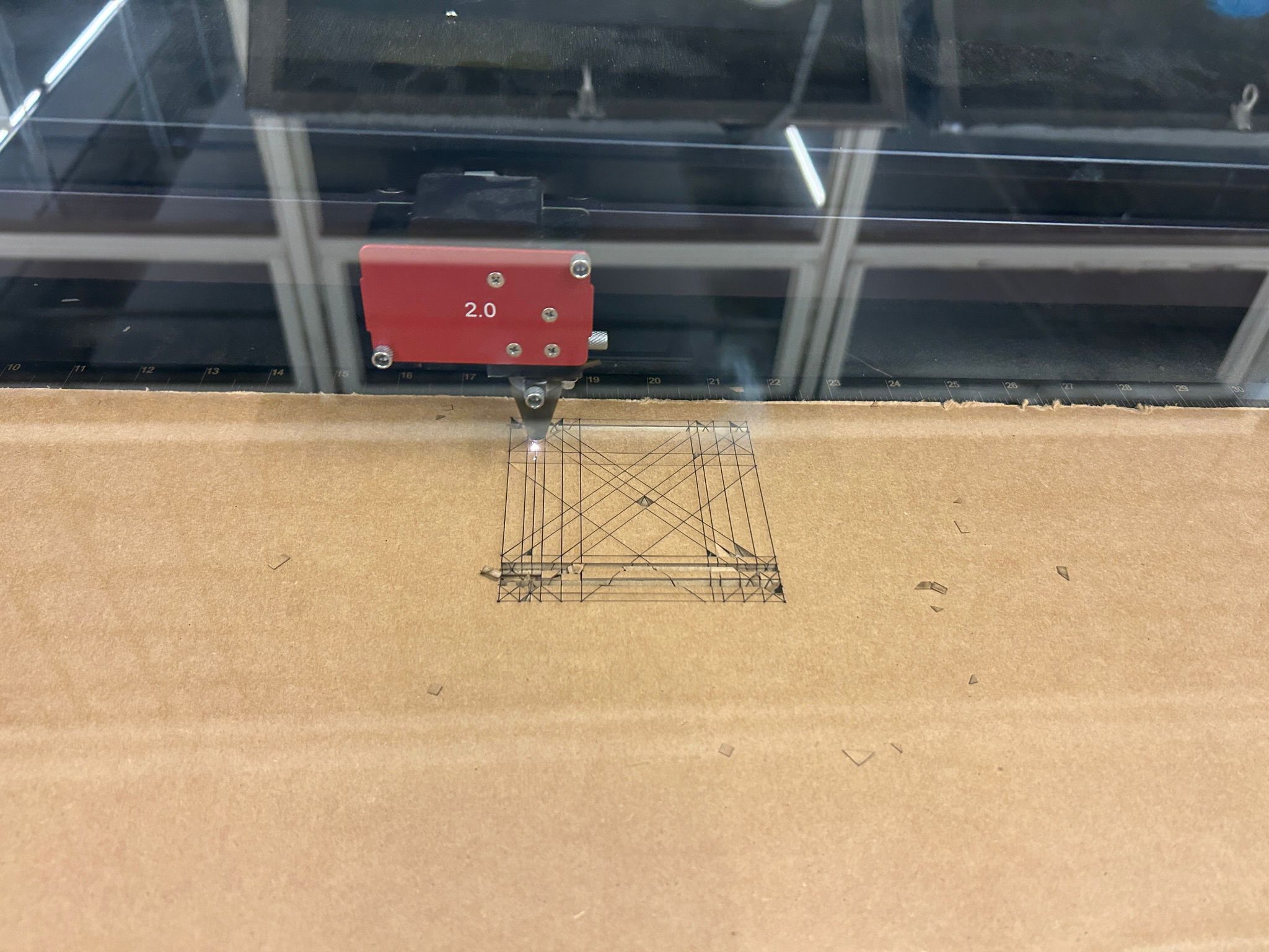
we did not take any images of the usl cutting software, but in there you can or select the laser power, speed, and frequency settings for your cut job for each color separately, and you can also move your print job on the lasercutter work area around, in case you use material that is smaller than the full bed size and you want to make sure that it is within your material. When you open the lid of the cutter, you can jog the print head to any area on the work bench and you should see a visible red laser dot to indicate where the laser is. We used this to locate the size and orientation of our test prints on the machine.
from there on we were ready to print/cut.
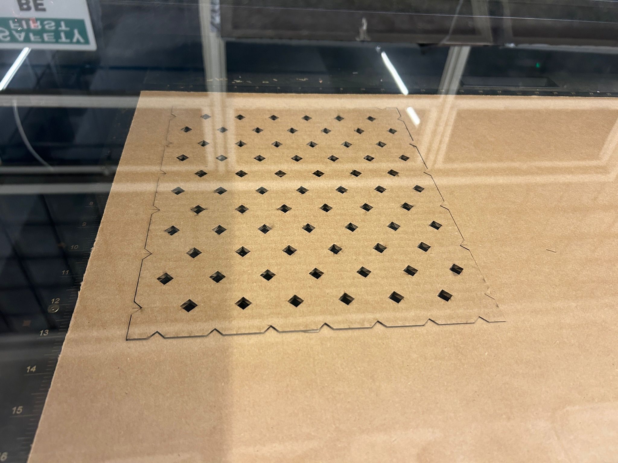
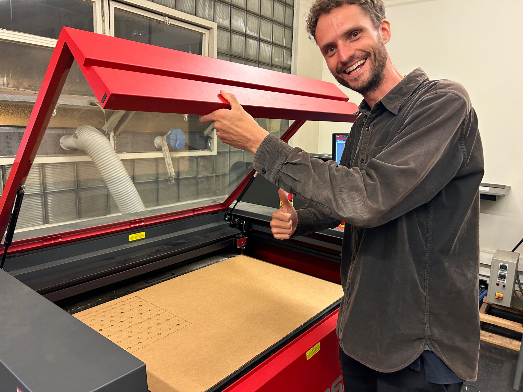
We did a couple of test cuts to see what we can do with the material that we wanted to use, but also to dial in the best settings for speed and power, that would be time efficient and not set the card stock on fire.
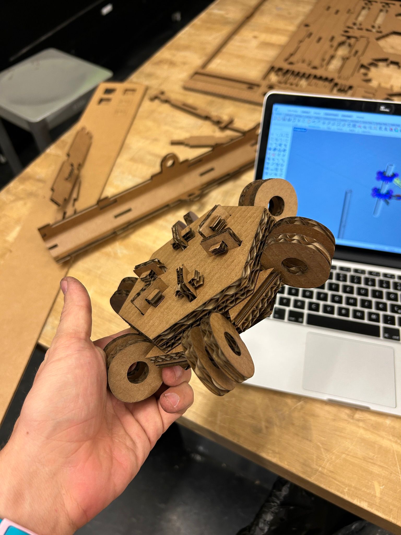
once we got everything ready, we cut this piece out of the cardboard and where happy with the results. the cut is clean, minimal burn marks and crisp edges. also, it just looks nice.
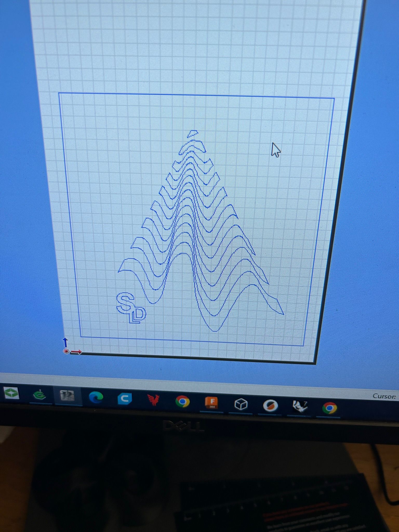
It is interesting to see which lines the software decides to cut first within the same color. while it works top-to-bottom in the print setting going from the top most color, to the ones on the bottom, the tool-pathing within each color category makes for interesting patterns during the printing.
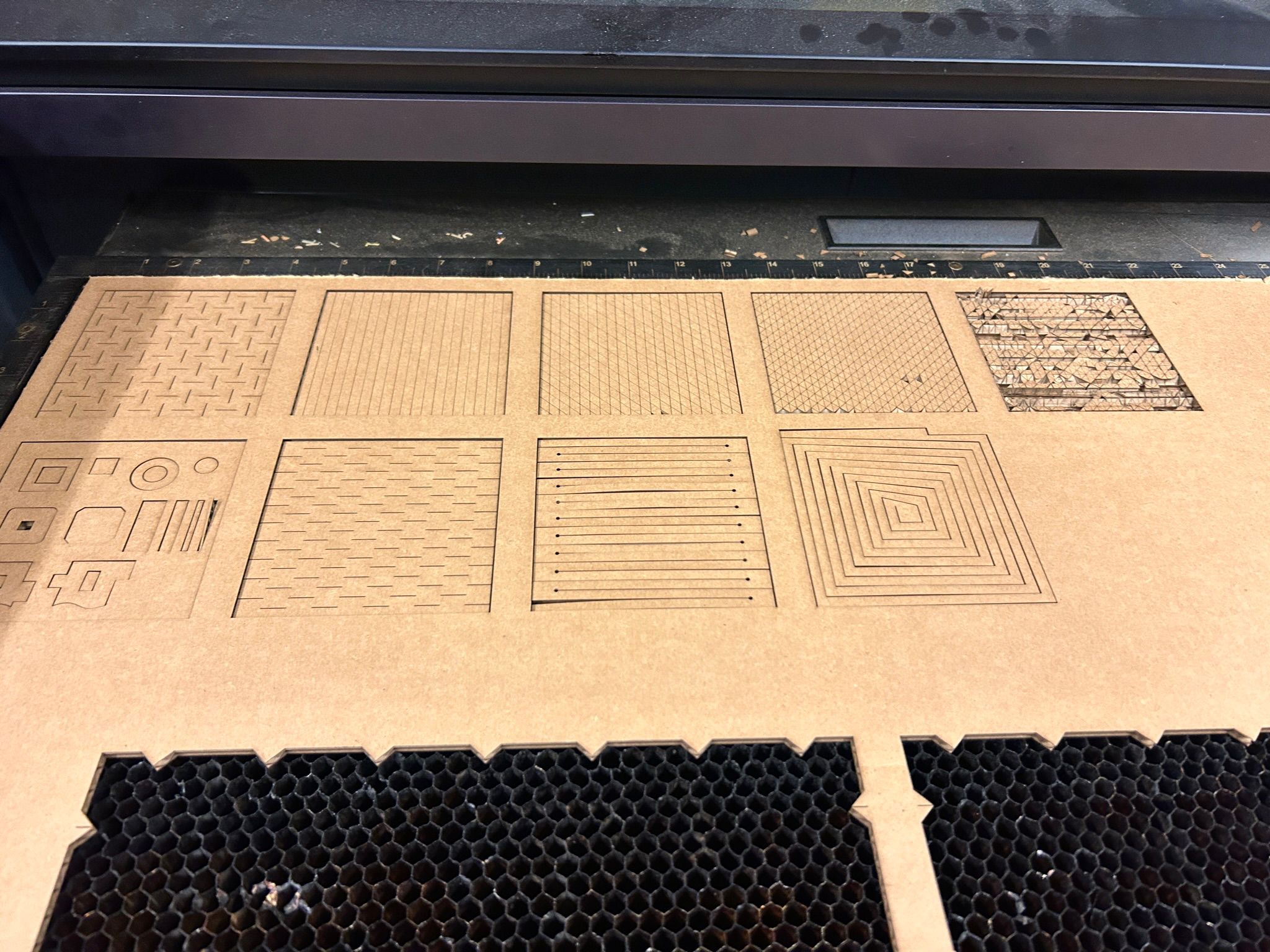
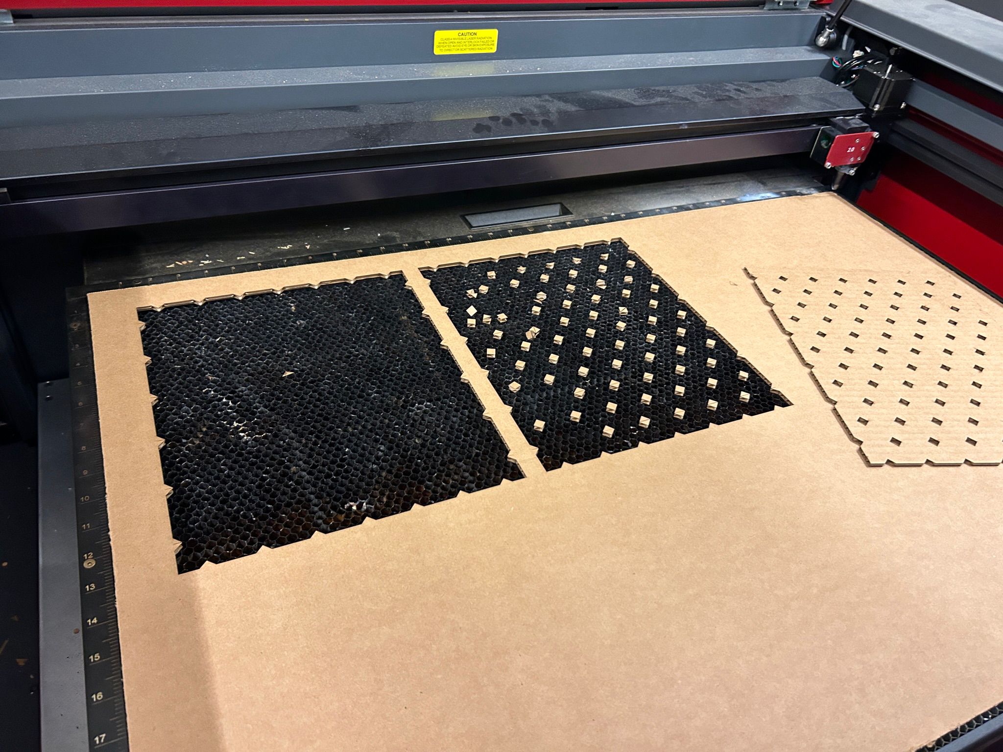
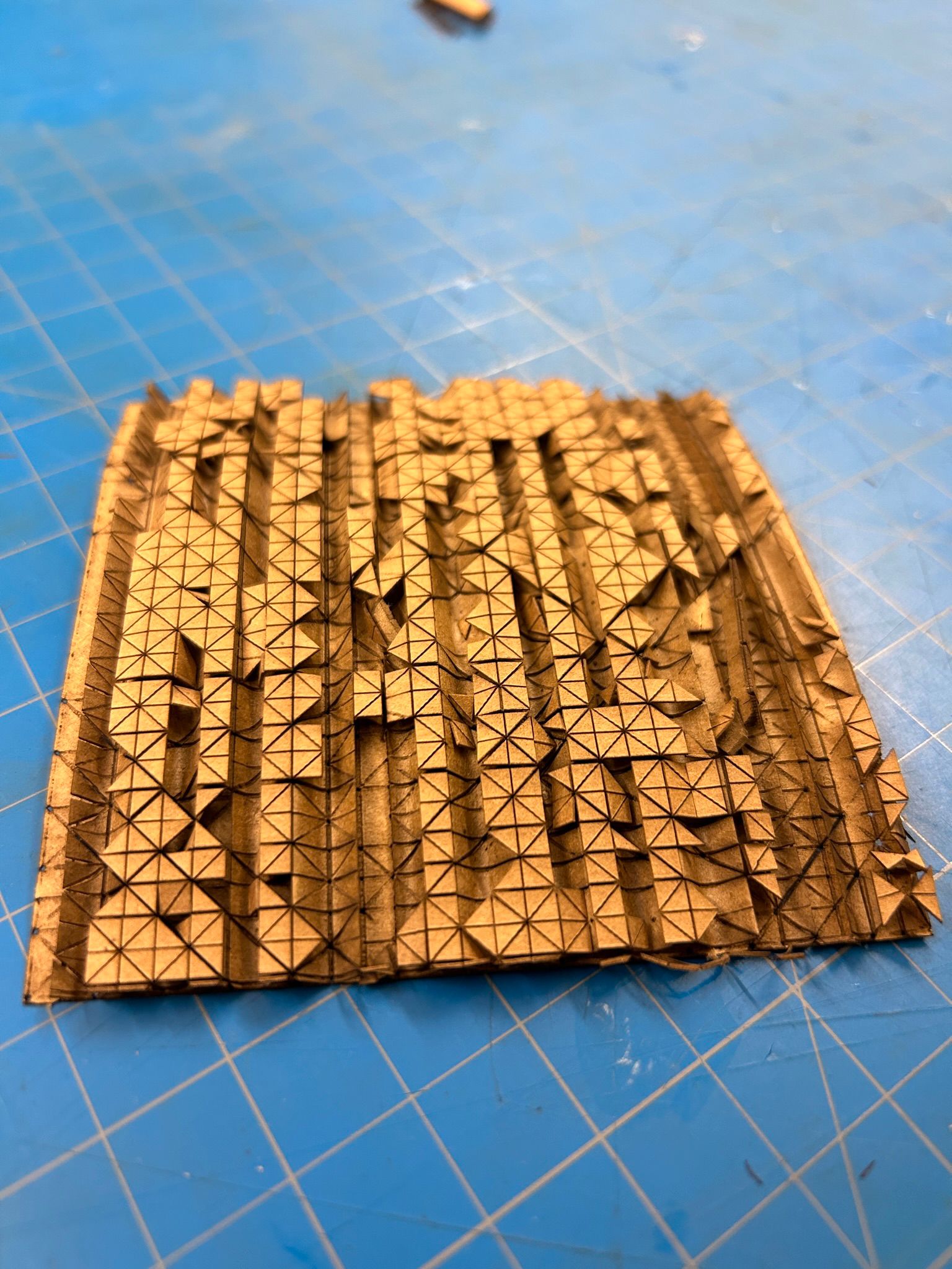
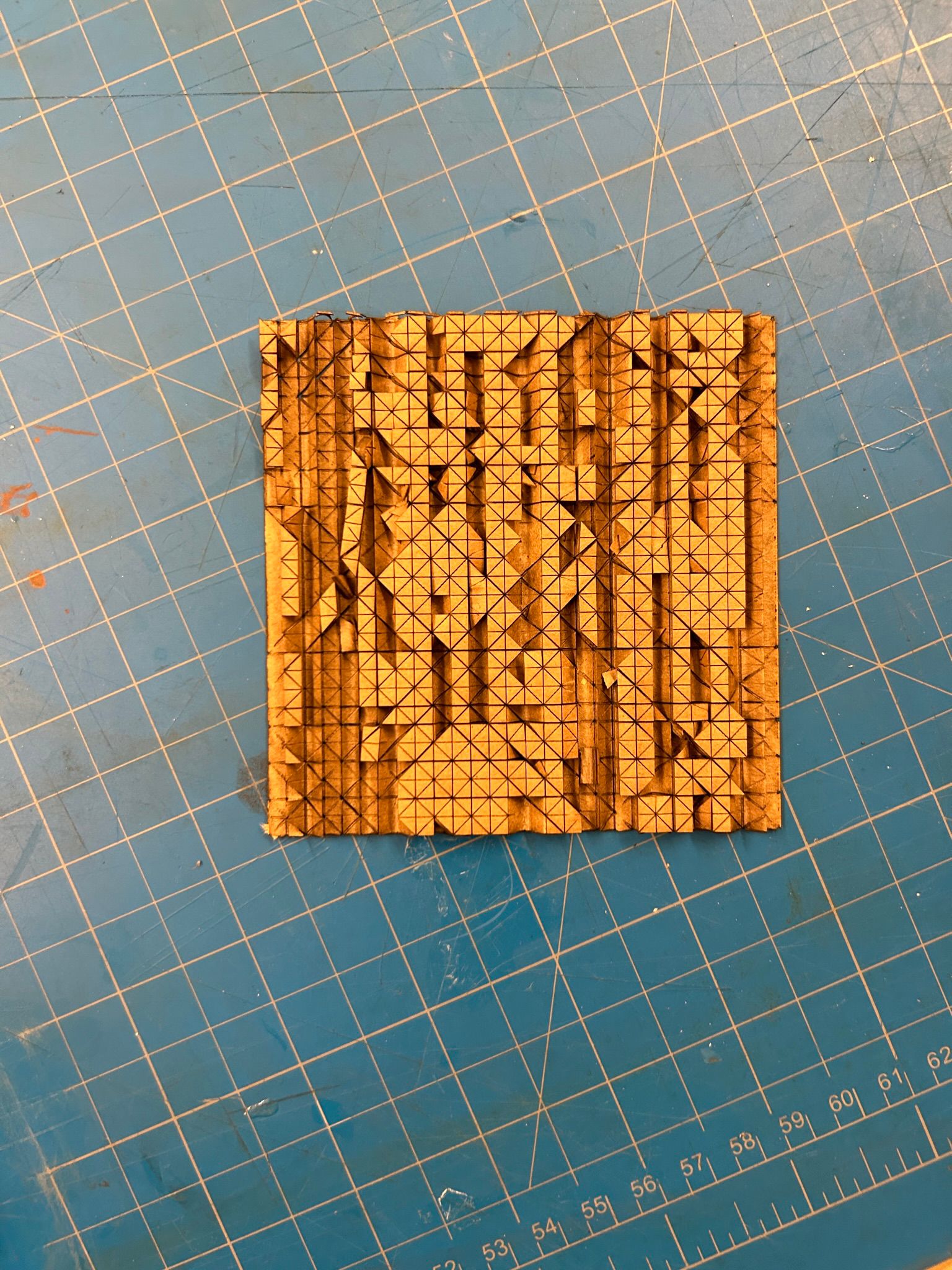
We came uop with 9 squares with different test cut patterns to test and experiment with the material properties.
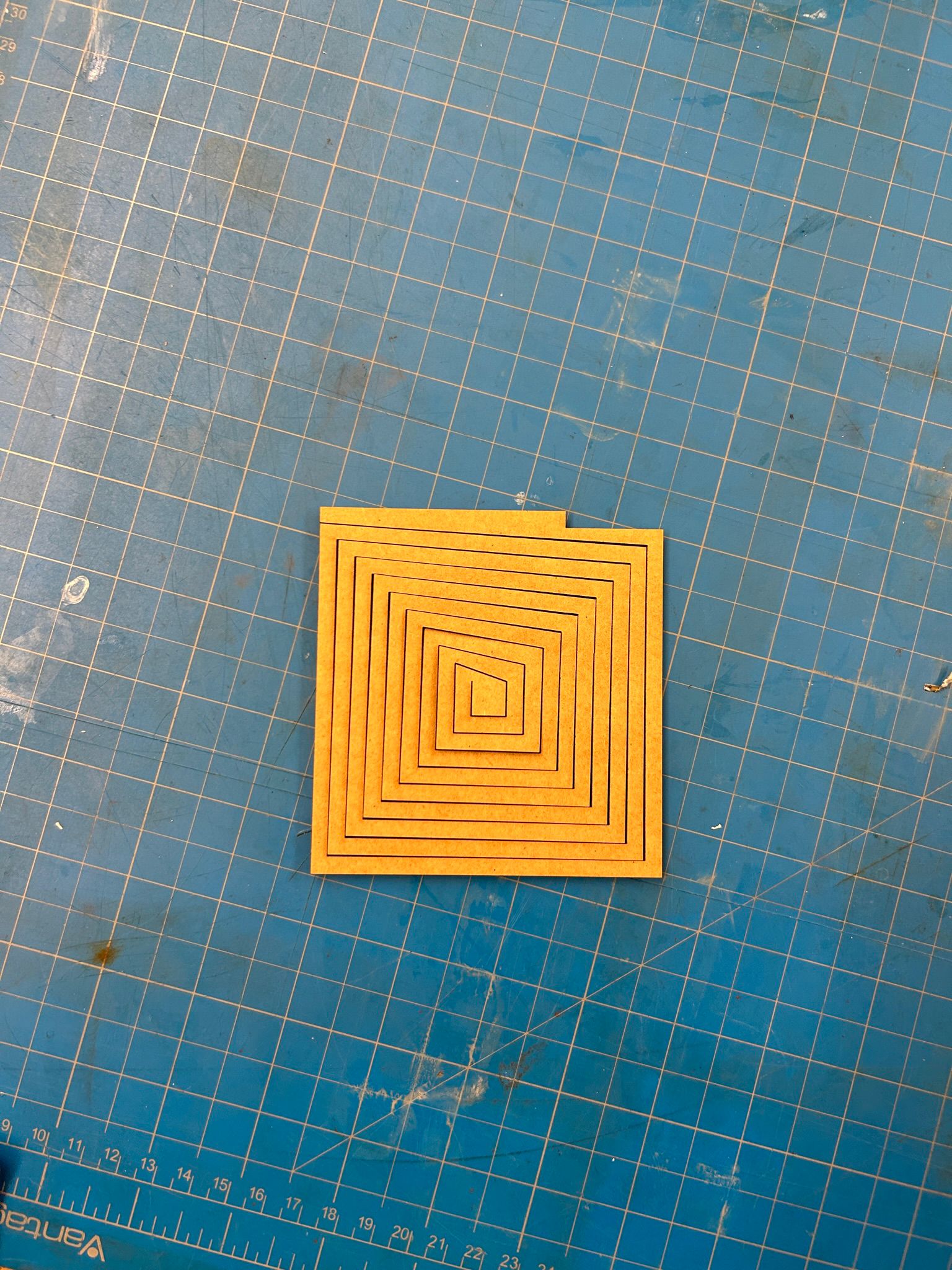
the first one is a spiral...
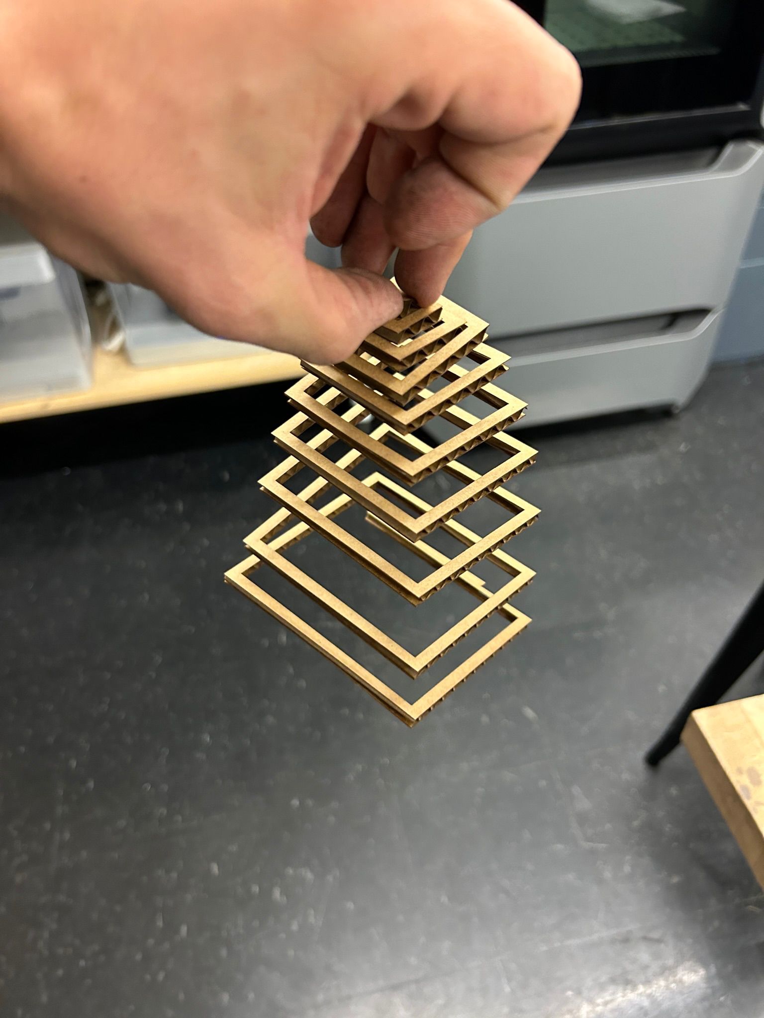
...which is able to expand from its center.
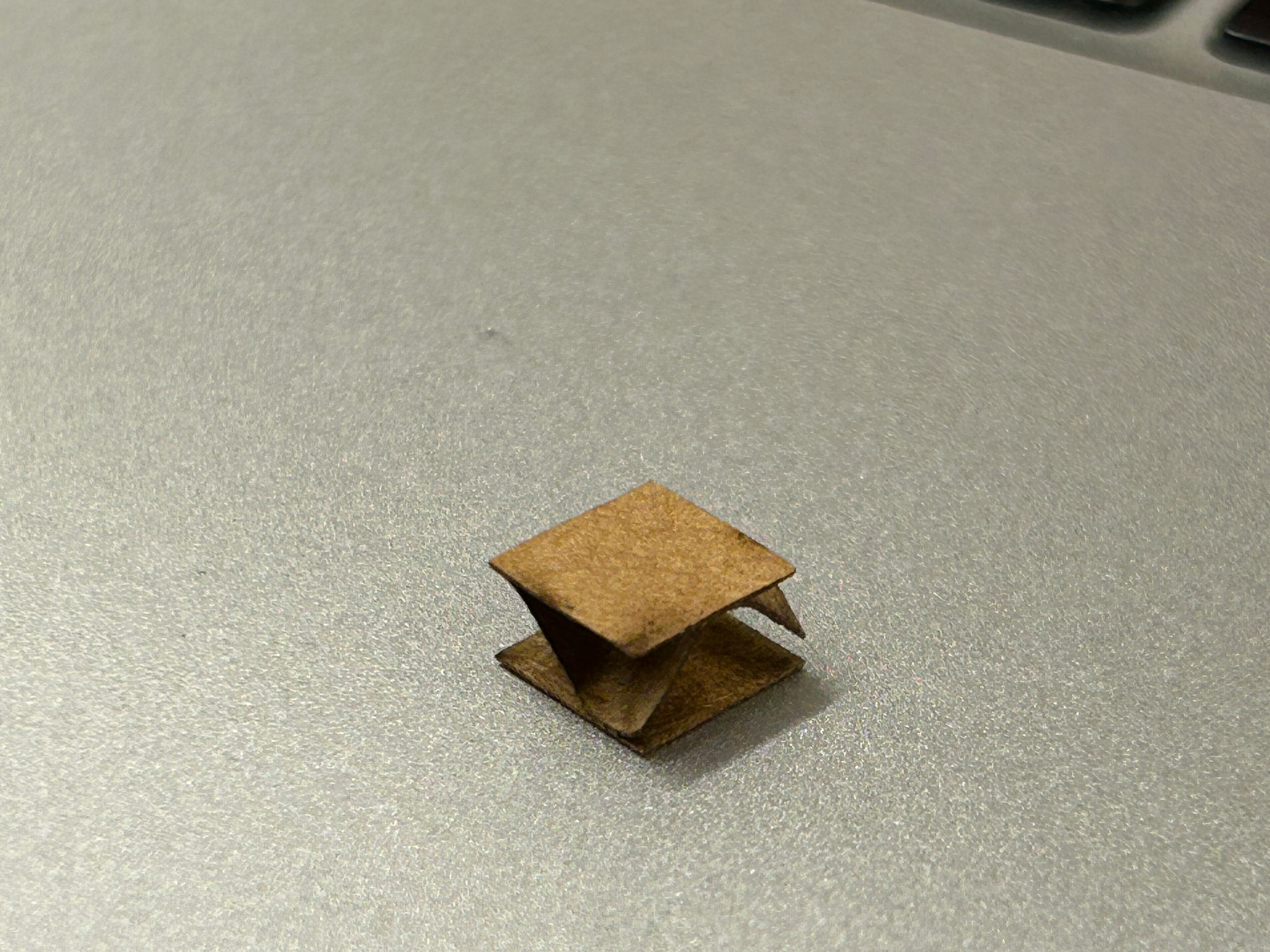
The second one is a diamond cut pattern, that was not aligned with the interior structure of the corregated card stock, and did not open all that good when bending.
but after a little bit of rolling it around...
... it would open almost like scales.
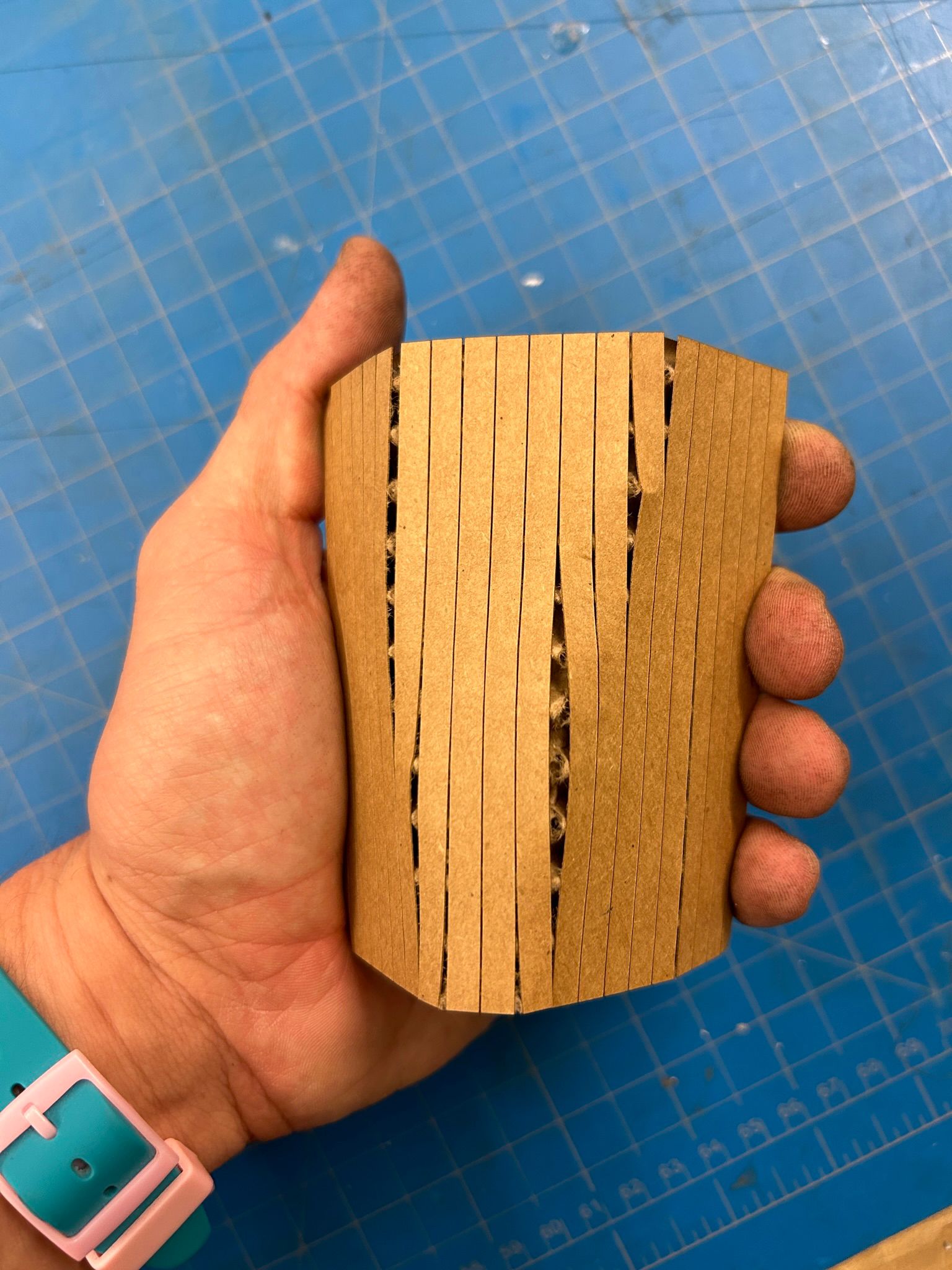
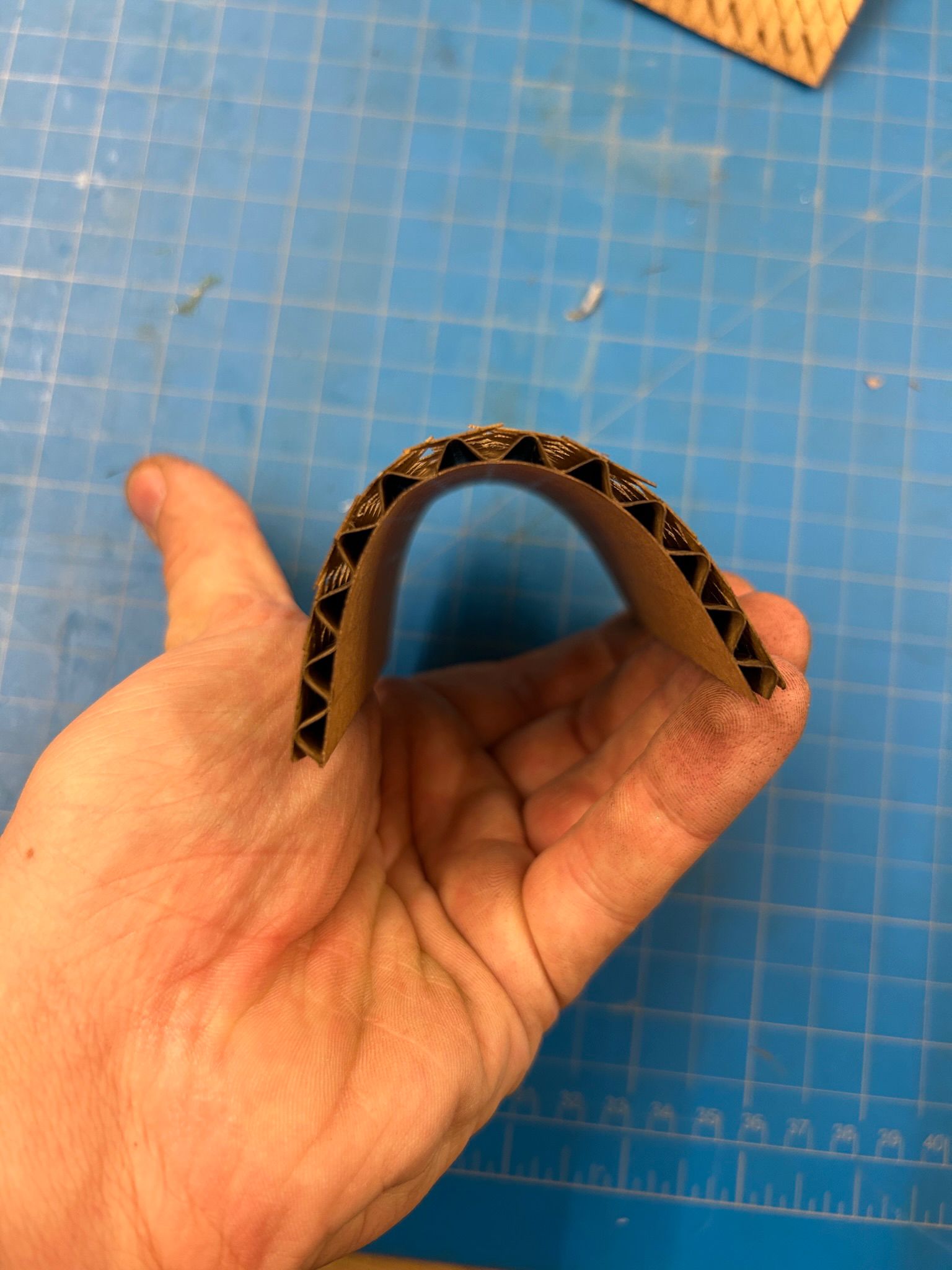
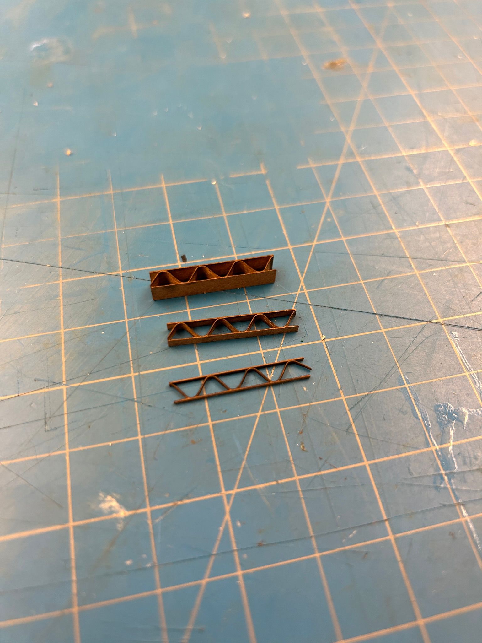
This one created a continuous band, going in a zig-zag up and down, followig the interior corregation of the card stock.
this made it very flimsy and bendy.
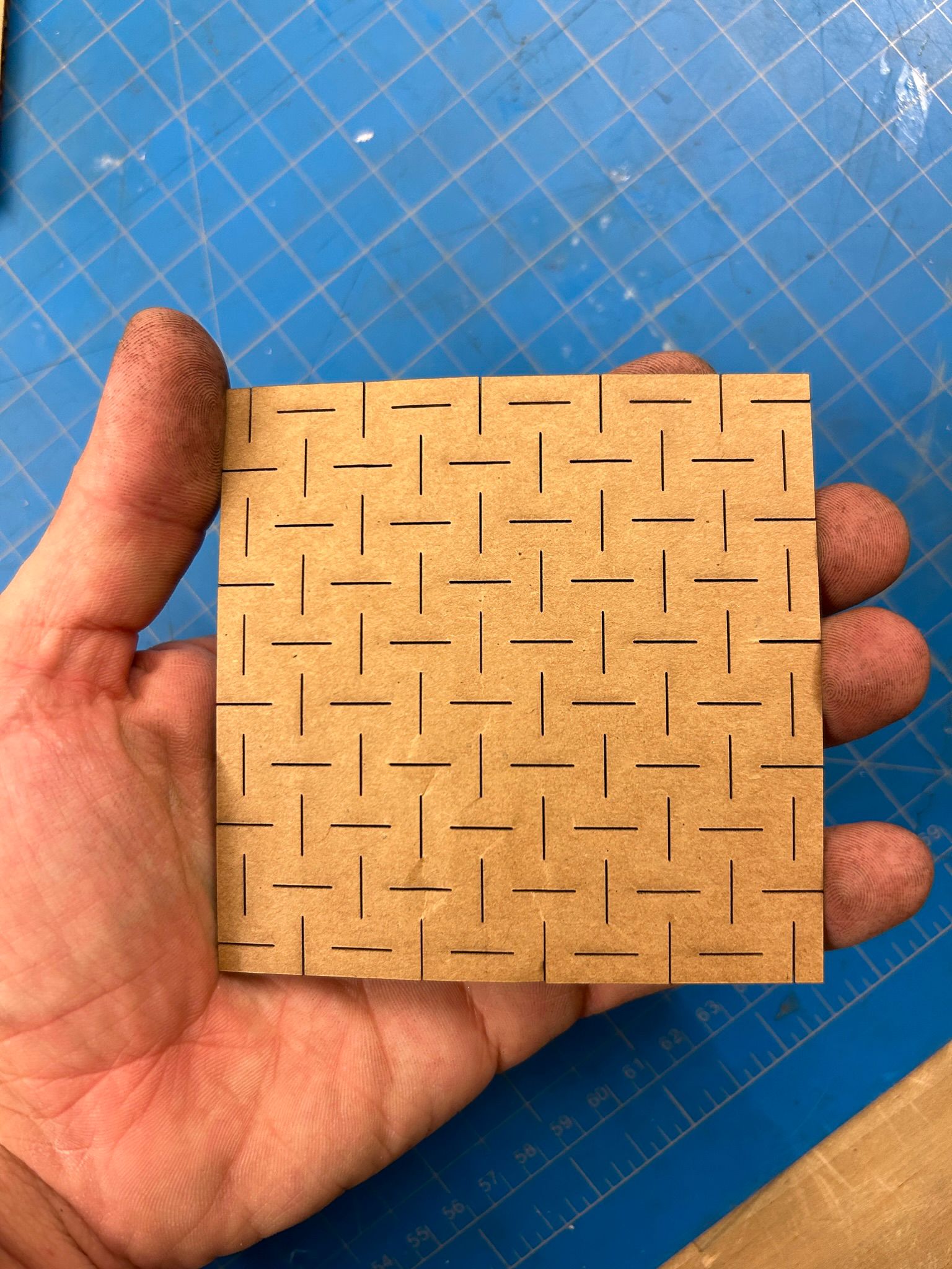
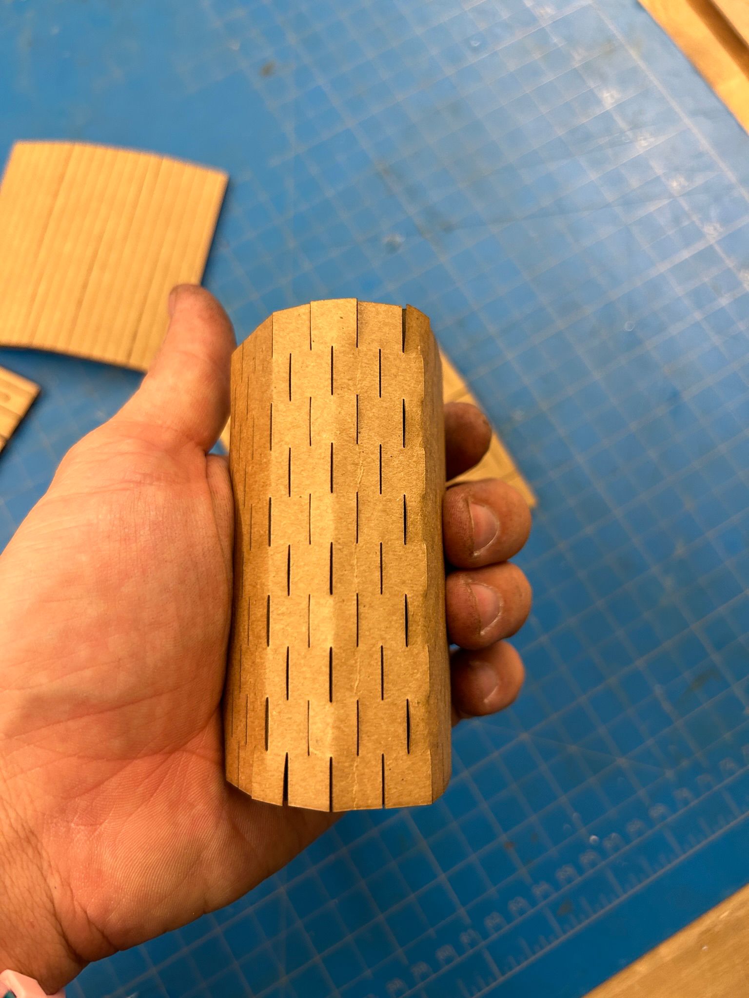
This next experiment tried to have a the scorig of the top layer in lines, perpendicular to the cardboard's corregation.
the two systems seemed to fight against each other when trying to bend it in either direction.
the offset two-directional cuts looked fun on the flat pieces...
... but did not perform in any particular way when bending it. It is possible that with a finer pattern a different effect could be achieved (we did not try).
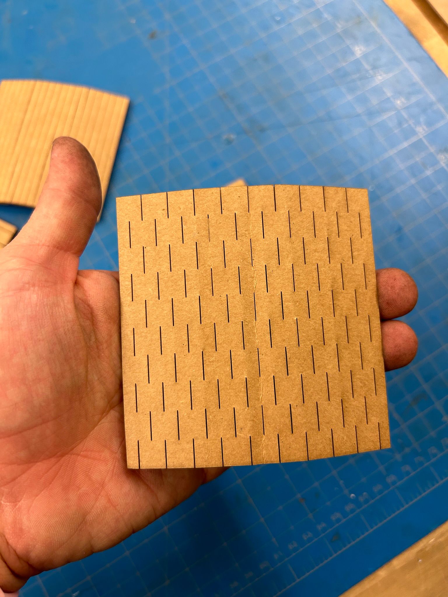
Similarly, the linear dashed-scoring did not have much more effect on the card.
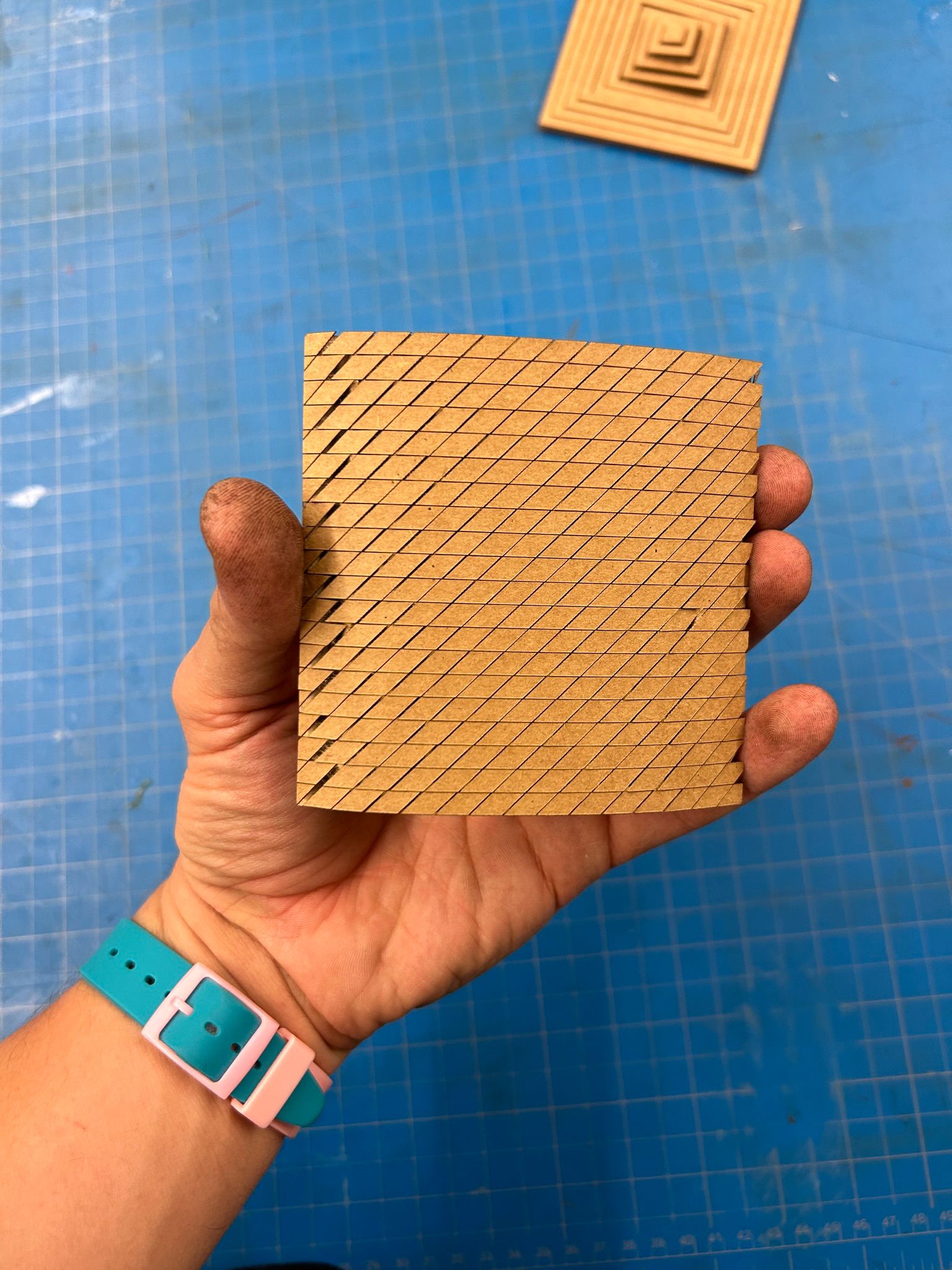
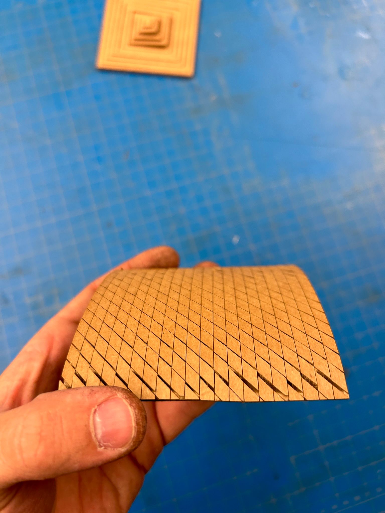
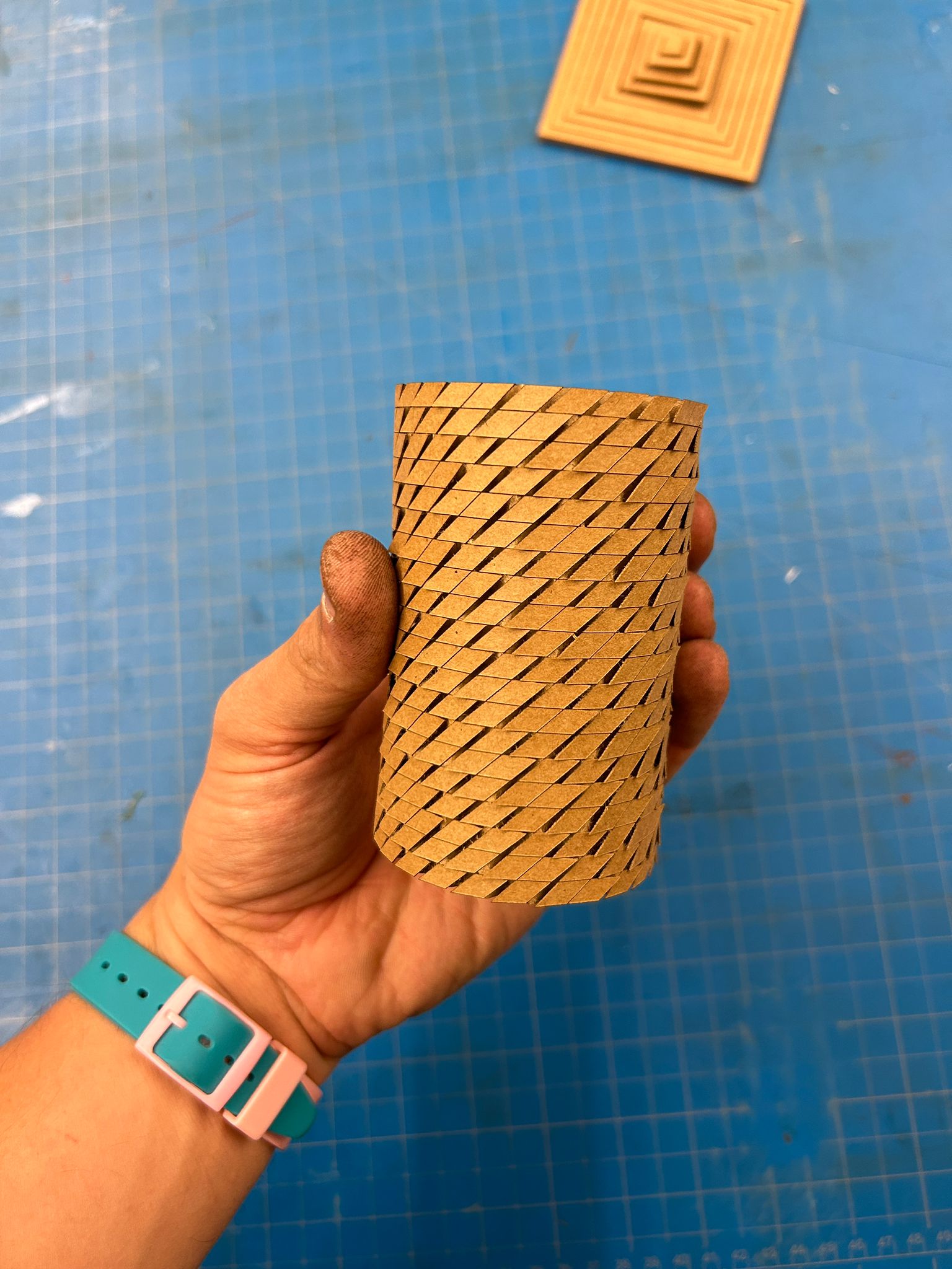
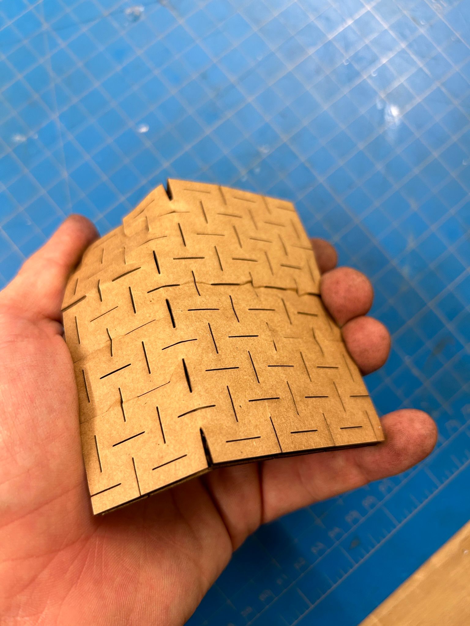
From here we used more lines to make the top layer of the material as soft as possible.
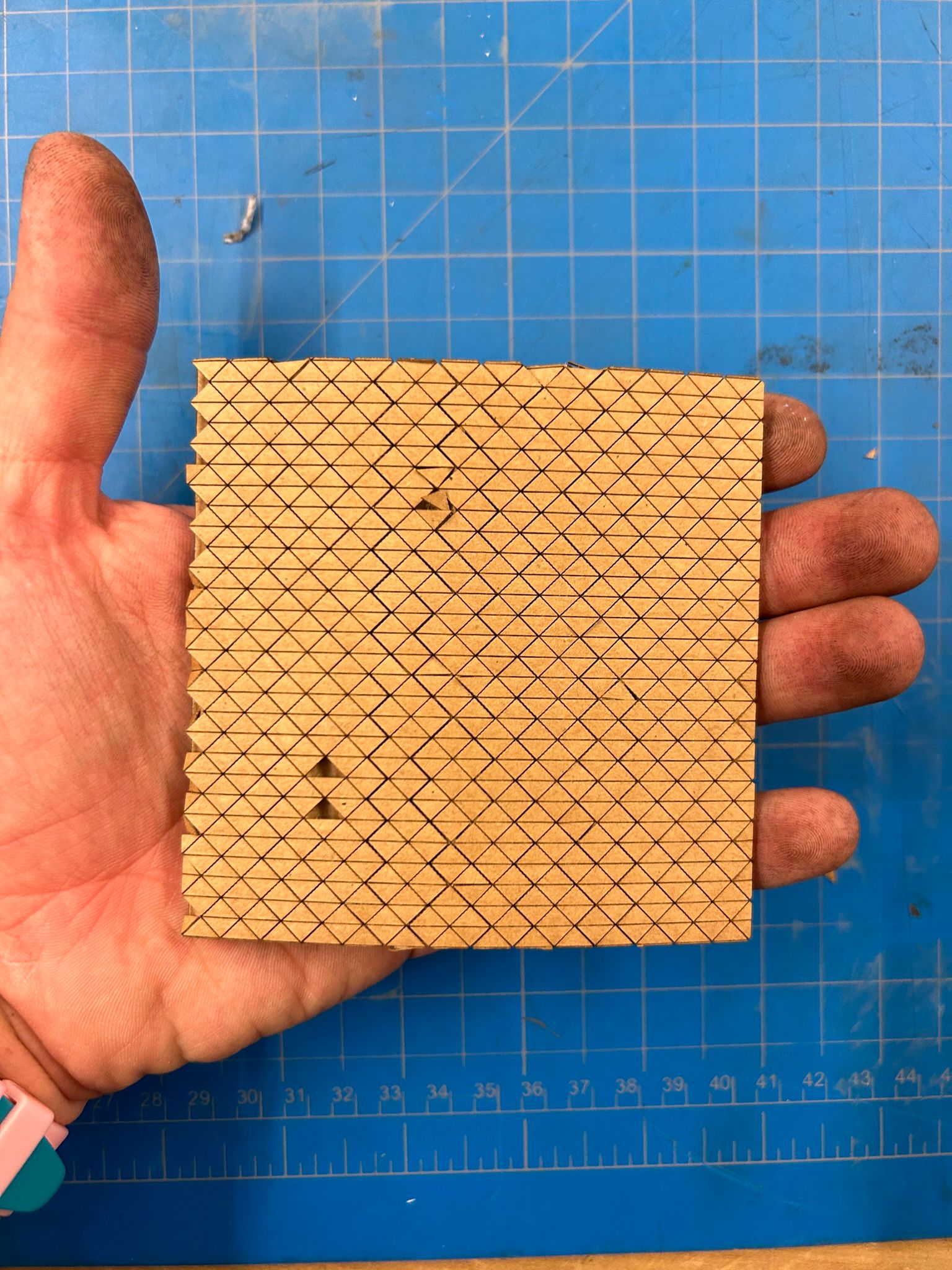
while bending this version, we observed interesting behavior of openings throughout the material.
in a side view, the material looks the same when flat...
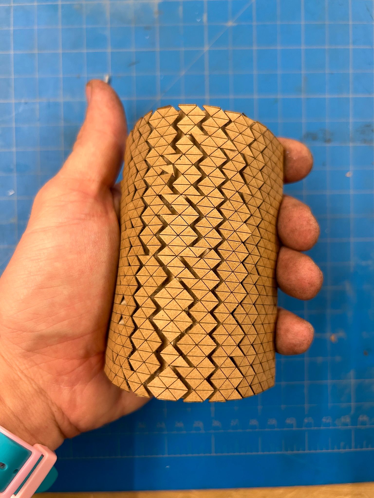
... but when we bent it we saw how the individual pieces of the top layer start sheering out and letting light into the middle of the material. it was key to keep the individual pieces larger than the corregation intervals, so they would not fall out when cutting.
Next we tried a few different versions to put two pieces together.
with wavy patterns
with finger joints
and with perpendicular, mid-board finger joint connections
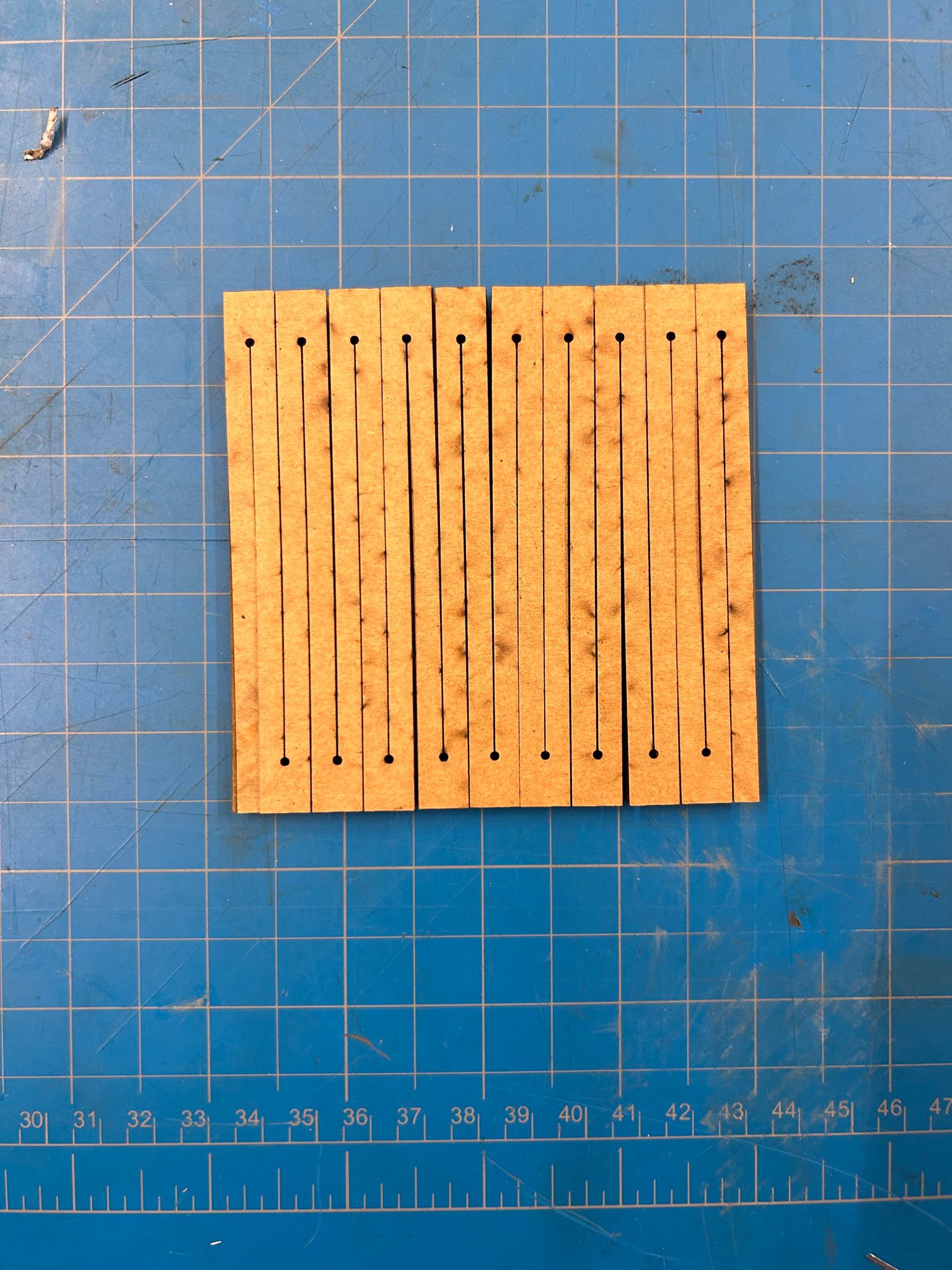
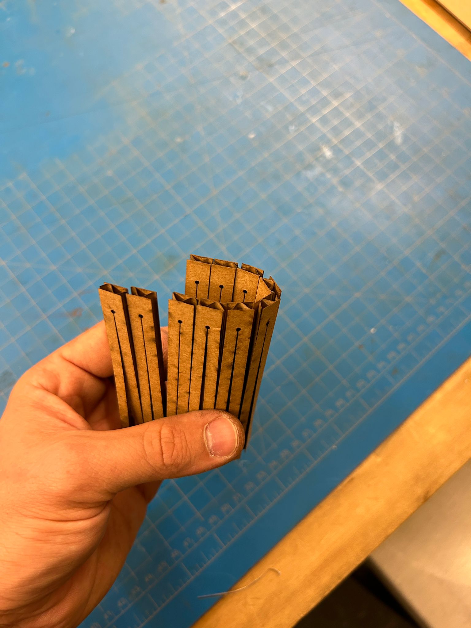
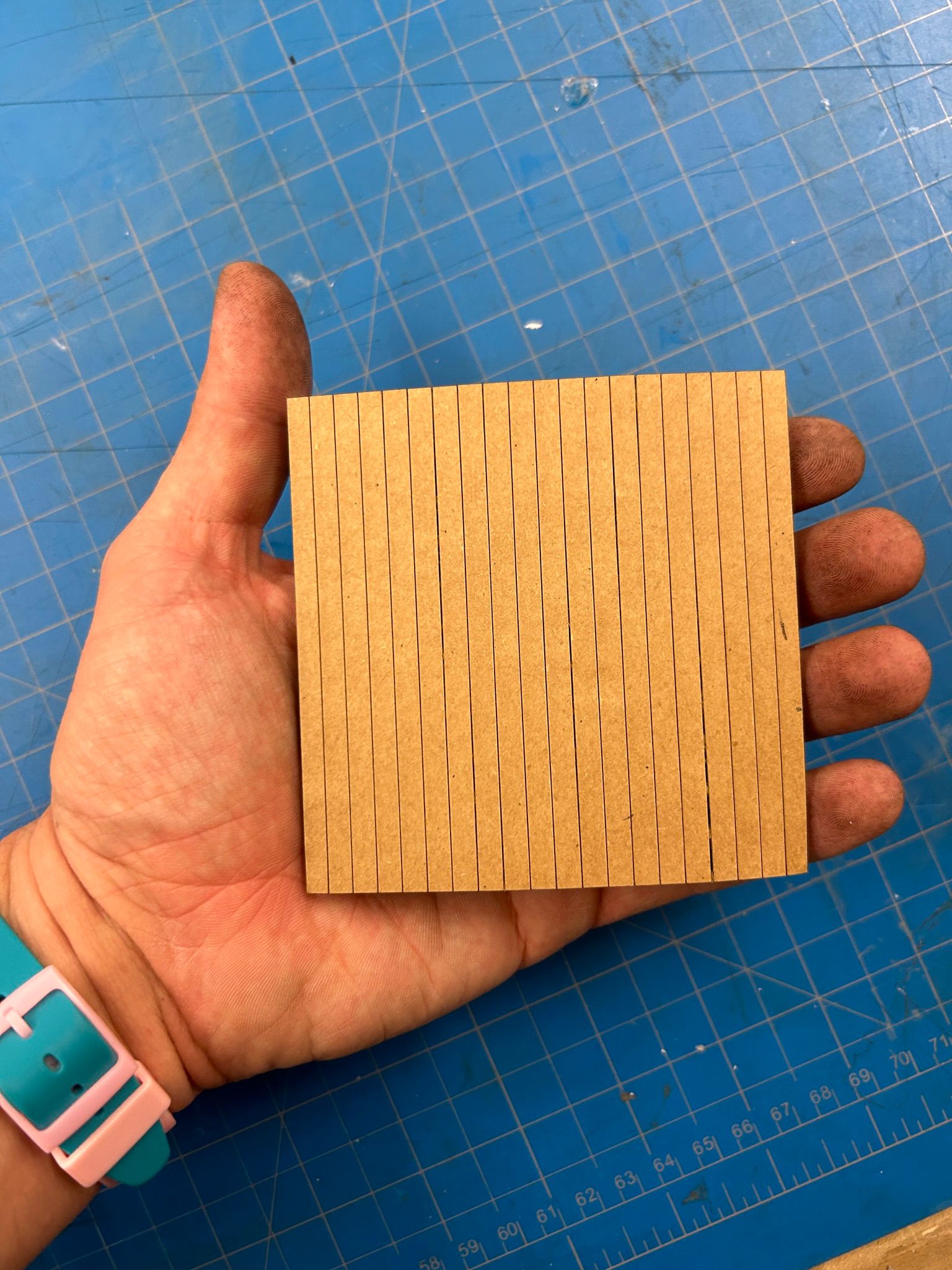
we also tried to see how thin our cuts could be, to extract a simple rectangular shape out of the cardboard, without burning the material.
Here is an interesting attempt, that shows how too small pieces scored in the top surface of the material are flying out due to the air pressure of the machine (that tries to keep flying particle away from the lens inside the print head).
the idea was to create a joint, a moving arm or object that I wanted to test prototyping with cardboard. flat stock material is not inherently used for movable objects, and the structural properties will make the construction of any movable element difficult
one of the challenges of the design was to construct the entire mechanism completely without any glued elements. the pole and the movable ring needed to be as solid as possible to withstand the stress on the material and the motion
the resulting idea was to do something counter ituitive, something that is not supposed to be made out of cardboard... it was yet again another rainy day in Boston, and that's where I thought to myself, something that really should not be made out of cardboard...an umbrella, the perfect challenge to try out the lasercutters
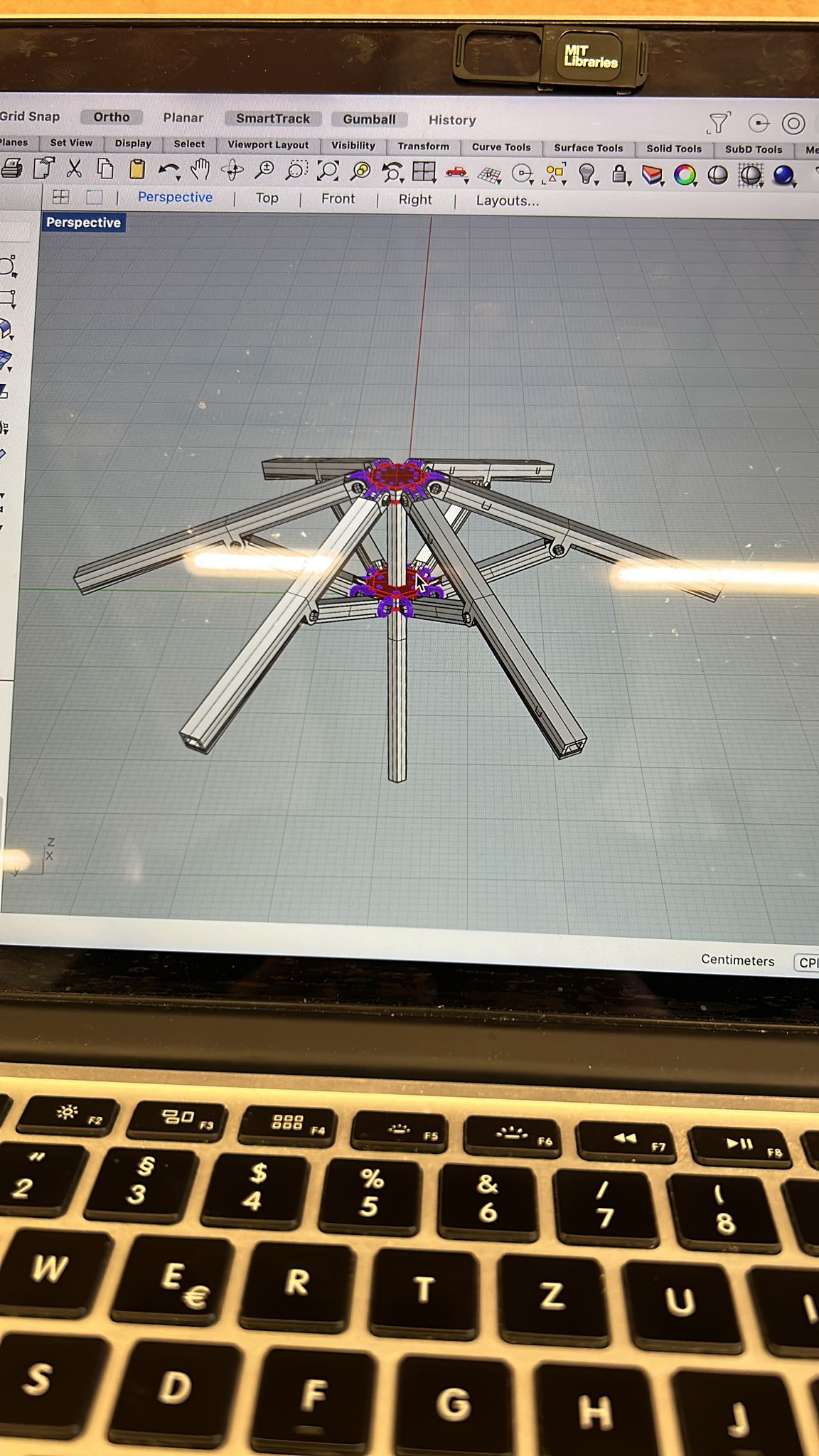
i started by 3d modeling my idea and the mechanism in Rhino3D. the biggest challenges was to find the sweet-spot of operability, size, and stability
for all of the moving elements. on one side we have the linear motion of the ring-like element along the pole (i decided to not have it actually round, but hexagonal to
prevent it from rotating along the pole), and on the other we have elements that need to rotate "freely" when opening the umbrella. I started
by modeling the umbrella with solid elements, and used the construction surfaces to make them into logical cardboard pieces with the correct thickness and tolerance.
after I believed that everything was working correctly, i copied the umbrella model to the side, and went piece by piece through the process of "exploding" the
individual parts, deleting all surfaces but the outer most, and used "unrollsrf" to get a flat copy of it in the x-y plane. I used the "silhouette" command to get the outlines
of the unrolled part, "join"ed the elements and grouped all the lines from the same part together so I can select and move them easily. I drew a rectangle in the dimensions of the
card stock that i wanted to use for this project, and tried to fit as many of the pieces on each sheet.
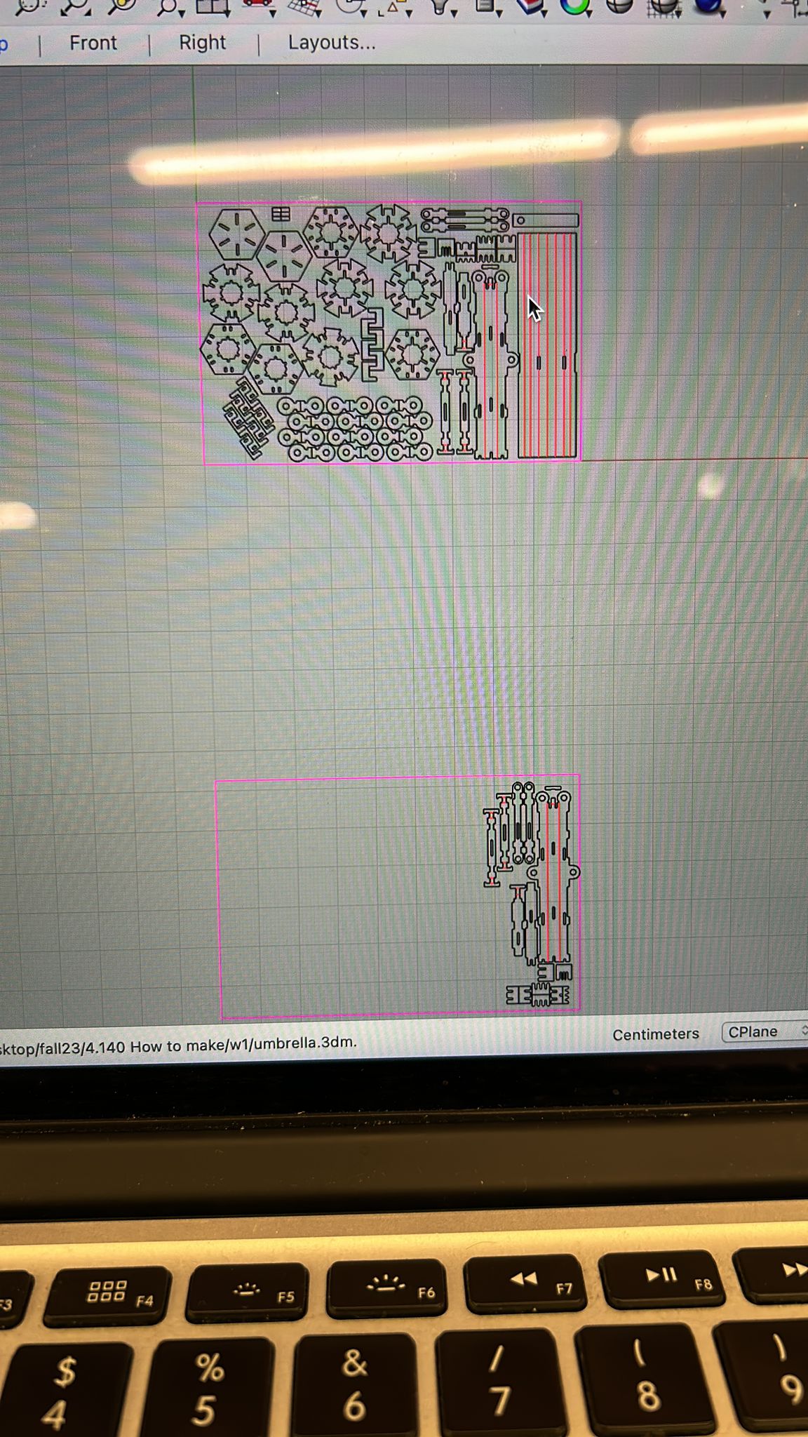
the material seemed to be difficult for my use. the direction of the interior structure had to be considered to make the larger elements structurally stable. however, much of the card stock was bend, and the laser went in and out of focus, changing the initially measure kerf
repetitive elements where organized to eliminate repeating lines of elements with shared edges in the cutting layout
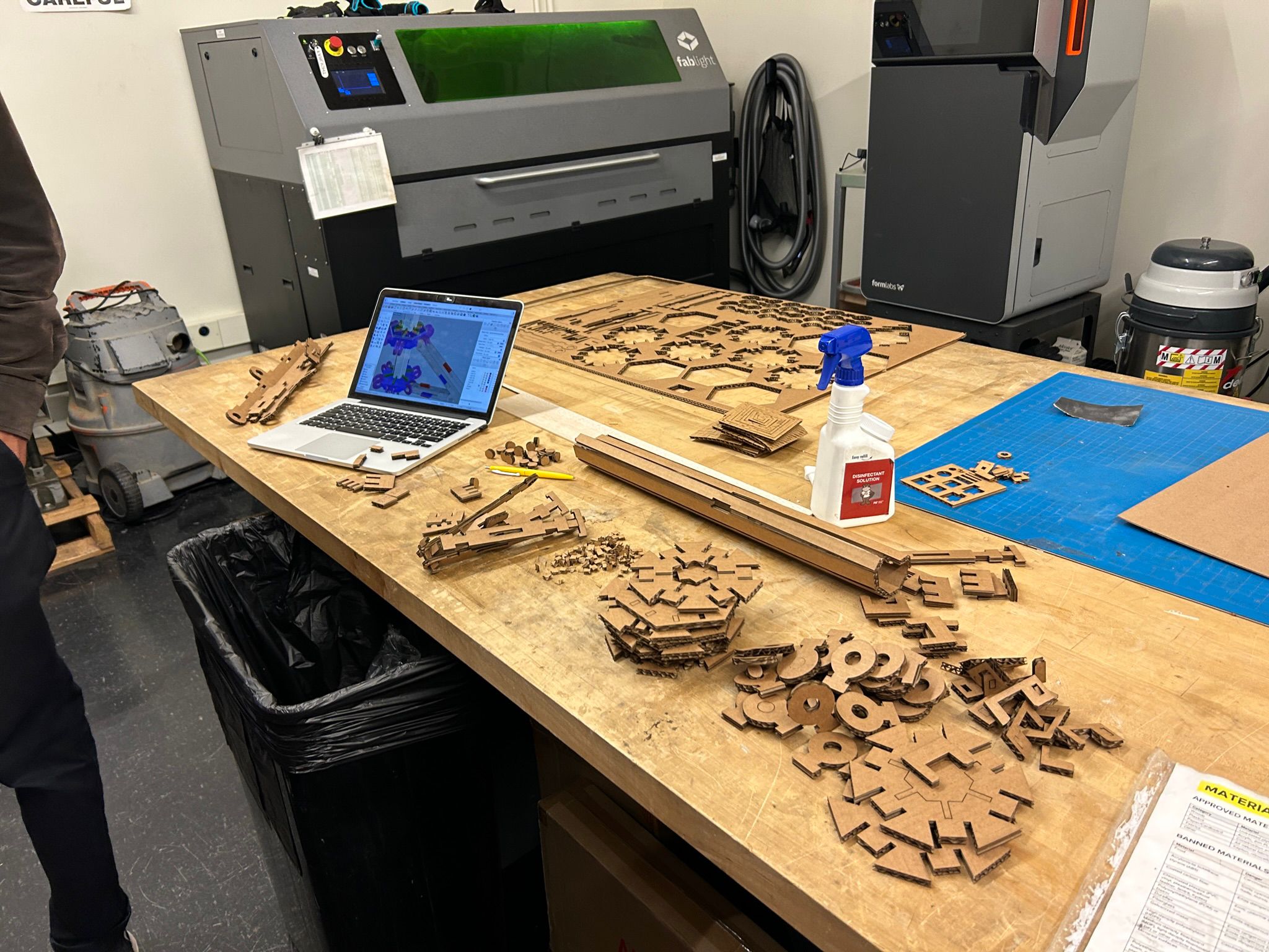
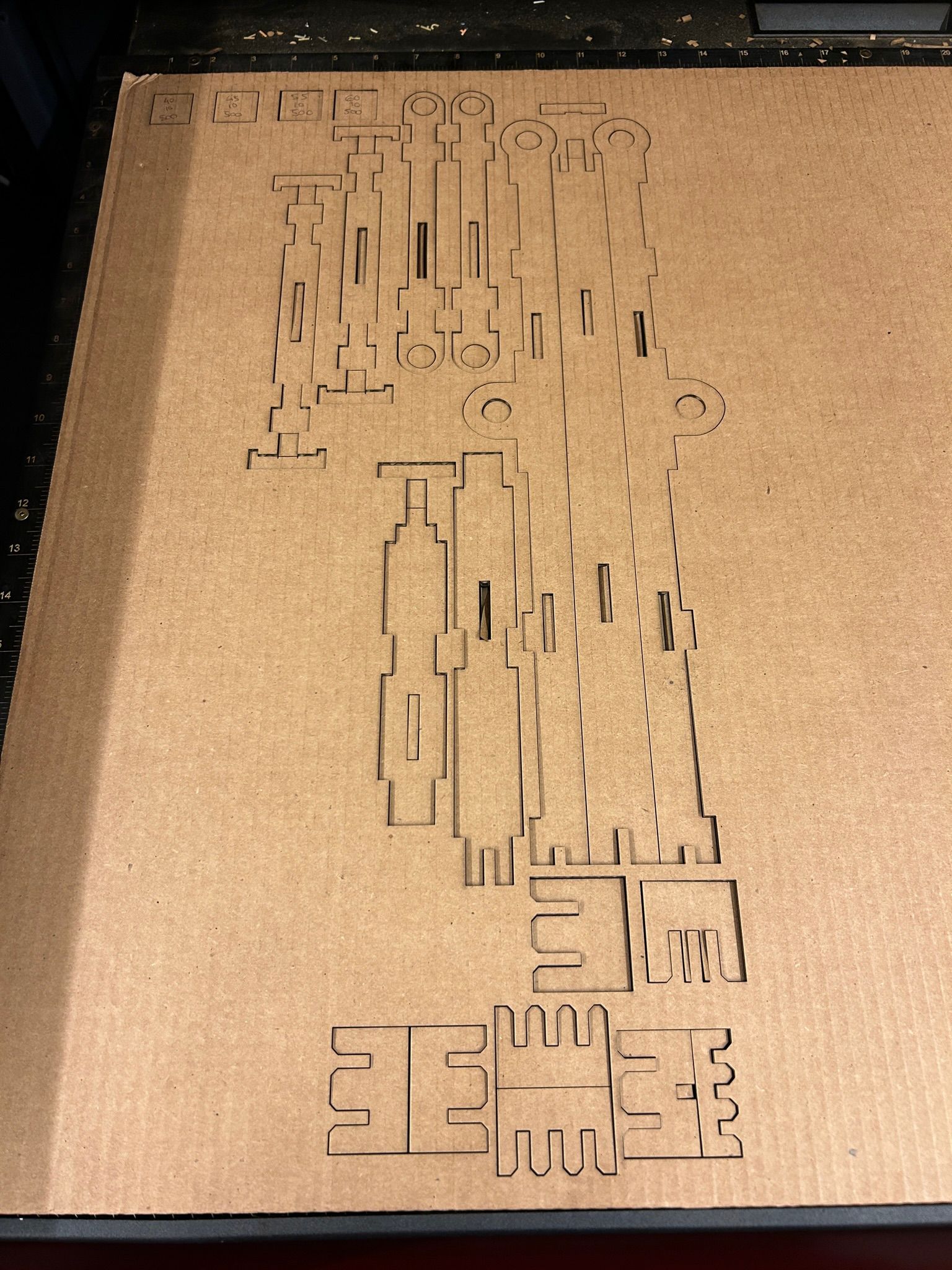
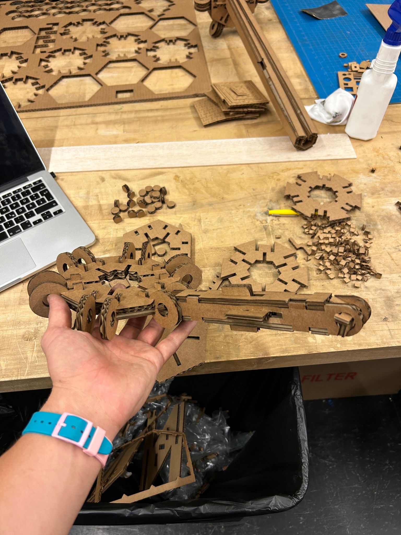
the result was a desk full of elements to assemble...
...and as little waste material as possible
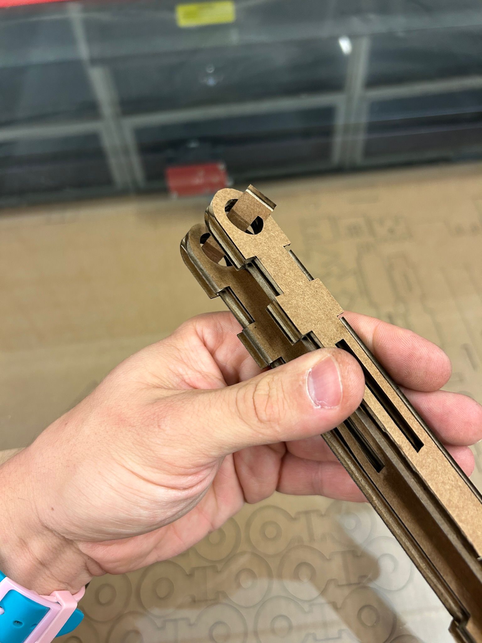
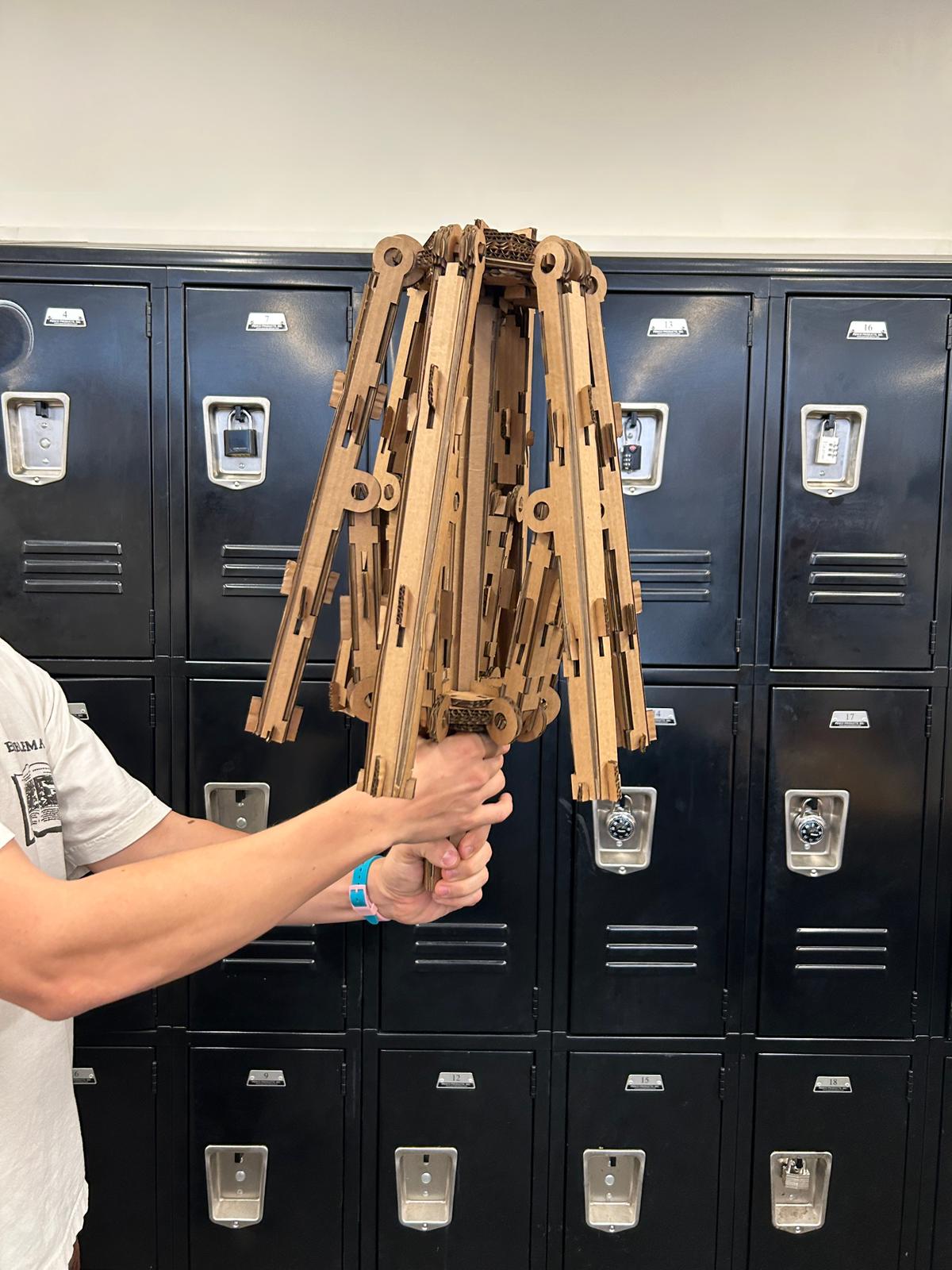
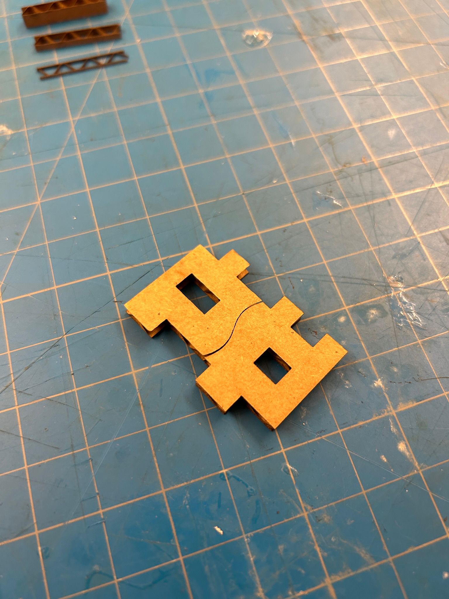
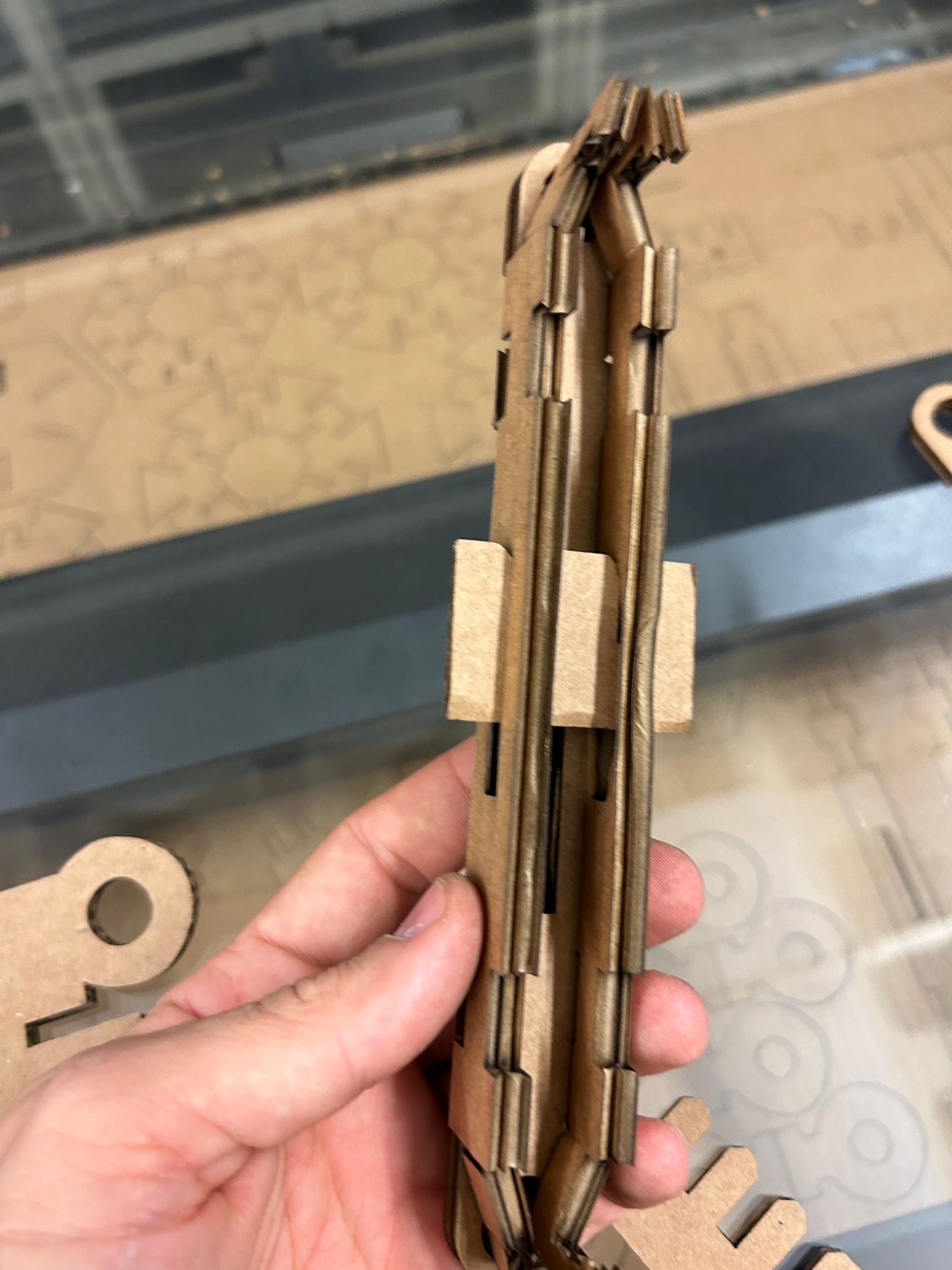
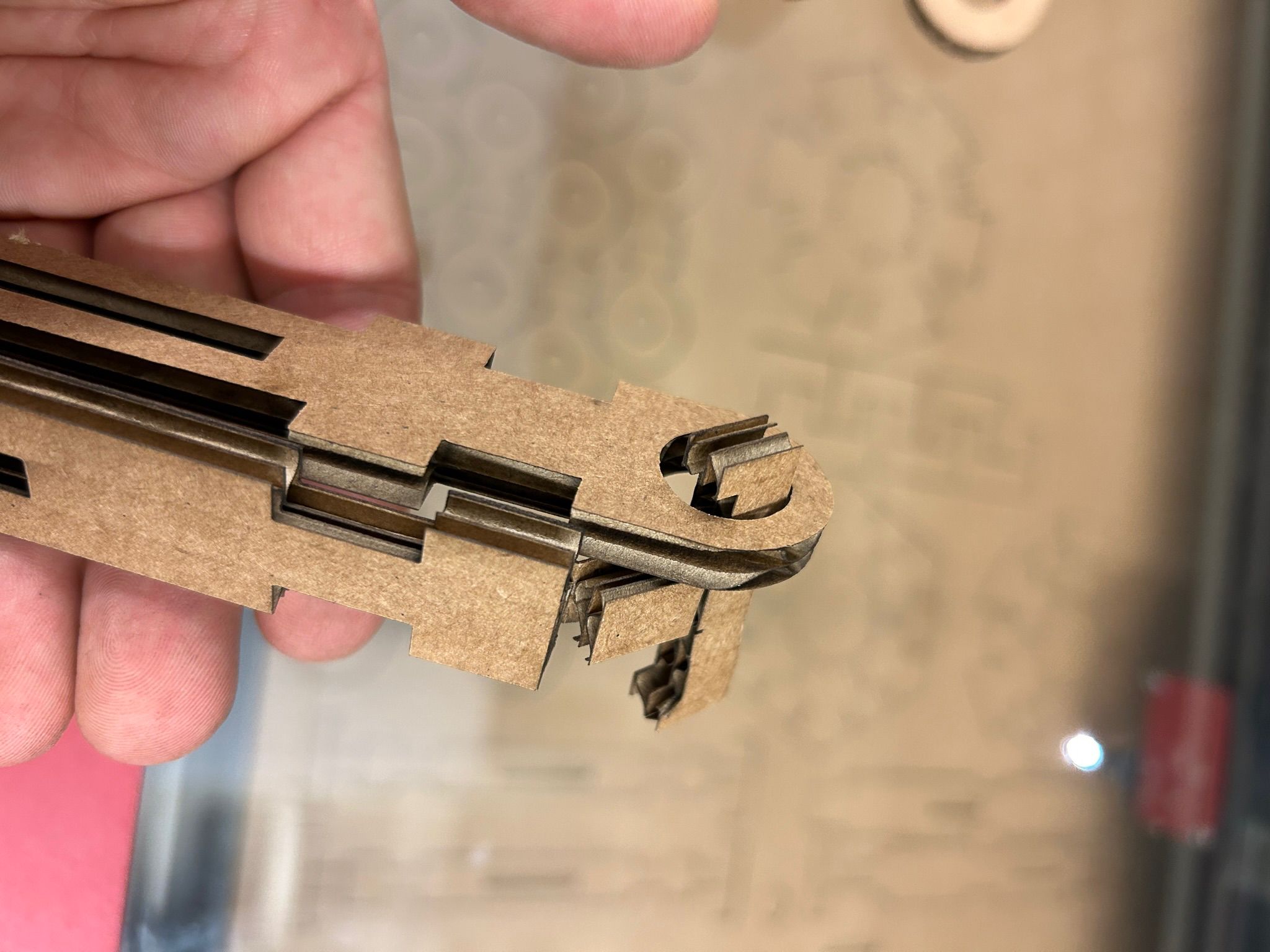
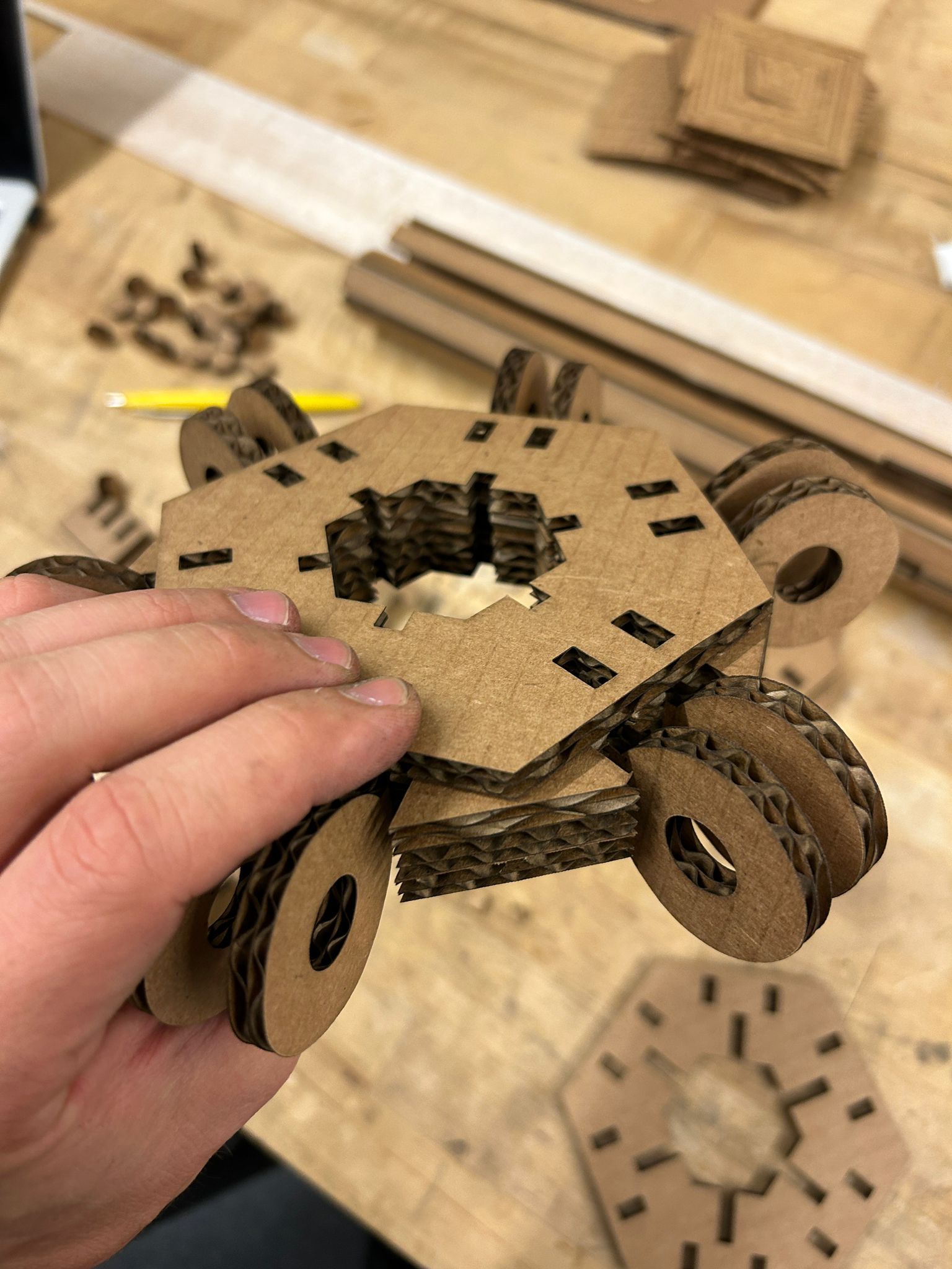
one of the challenges for the mechanism, was for the individual arms to be as rigid and stable as possible, while using as few parts as possible. interlocking edges set the parts into place, while a folded T-shape connect through the hinge and turn into the axel of the joint
another challenge was to asseble a ring where all the arms would connect, so that a single element would need to be moved to controll all the parts a big consideration was the elements not only to be stable, but also to connect in a way, in which they lock each other into place.
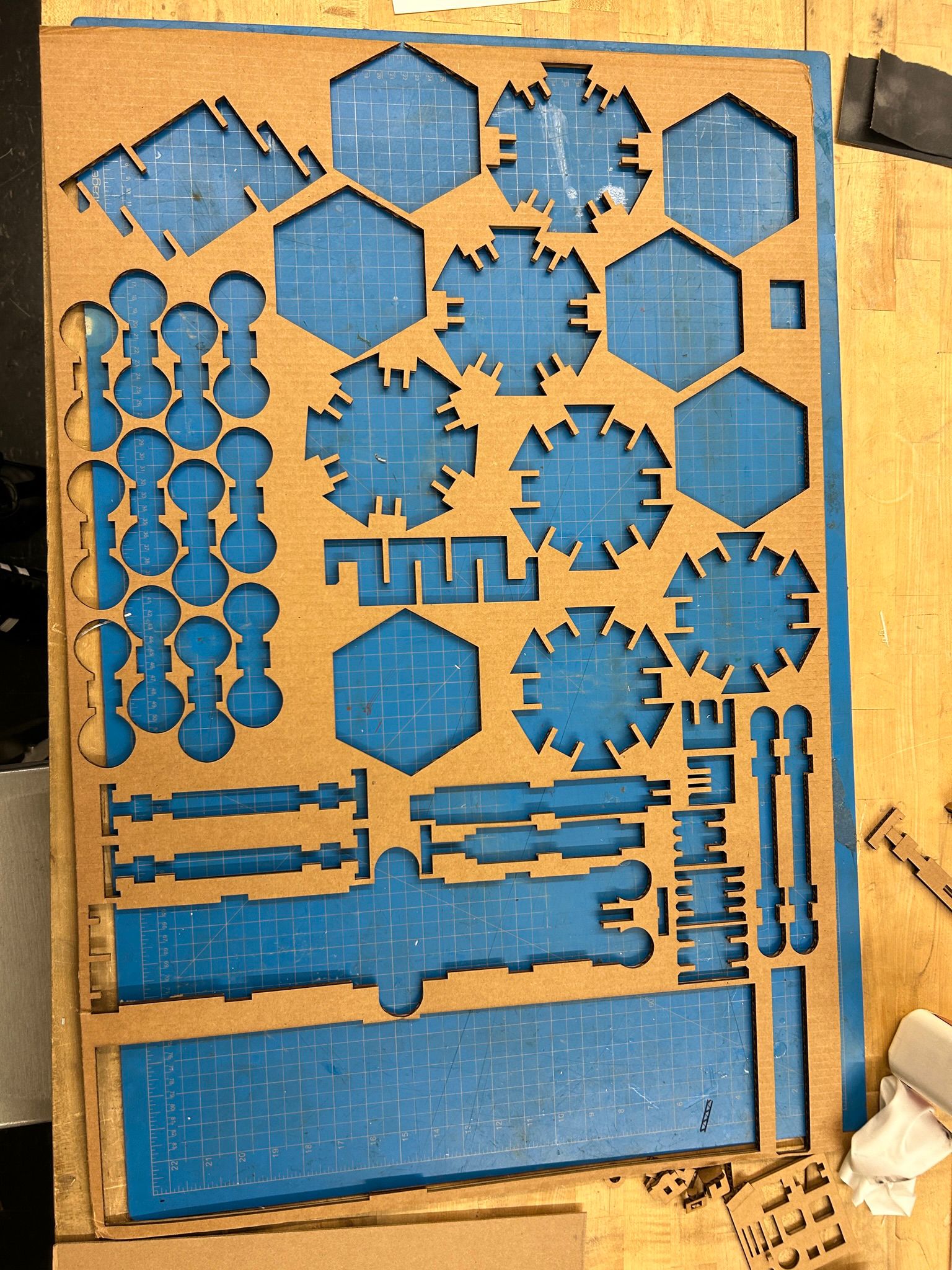
my solution was to layer a few of the hexagonal plates together, and leaving some notches for the ring elements that would become part of the rotating joint for each umbrella arm.
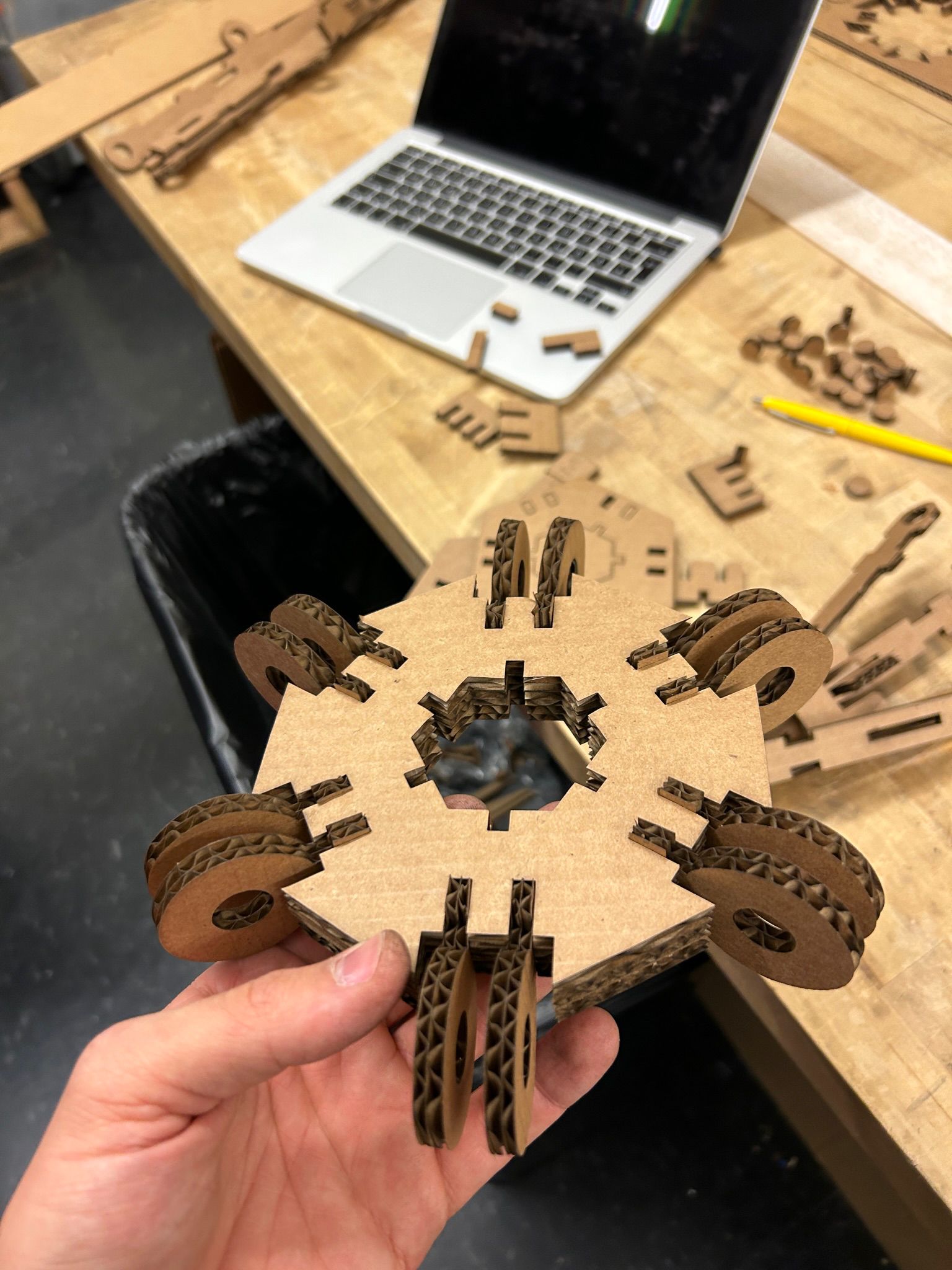
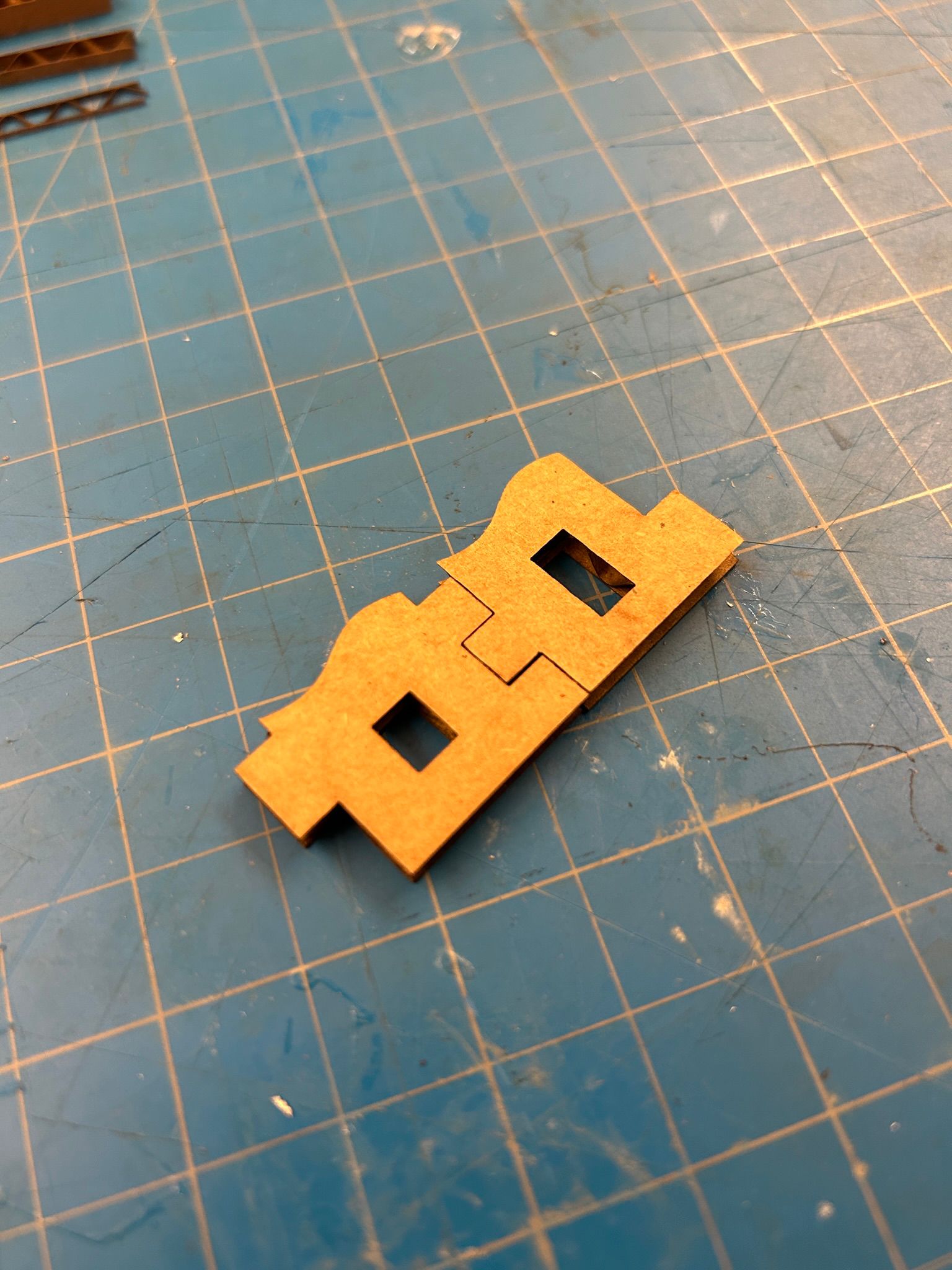
i planned it so that the notched pieces would be longer than the two layered hexagonal pieces, so i would be able to have an additional plate on the top and bottom added, that does not have the complete notch, but only a rectangular hole. this would prevent the ring elements from falling out.
after this i added some c-shaped elements in the center, that would hold all the things together from the inside. once this larger ring would be added to the hexagonal pole, the c-shaped pieces would not be able to be removed and the assembly would not be able to fall apart by itself.
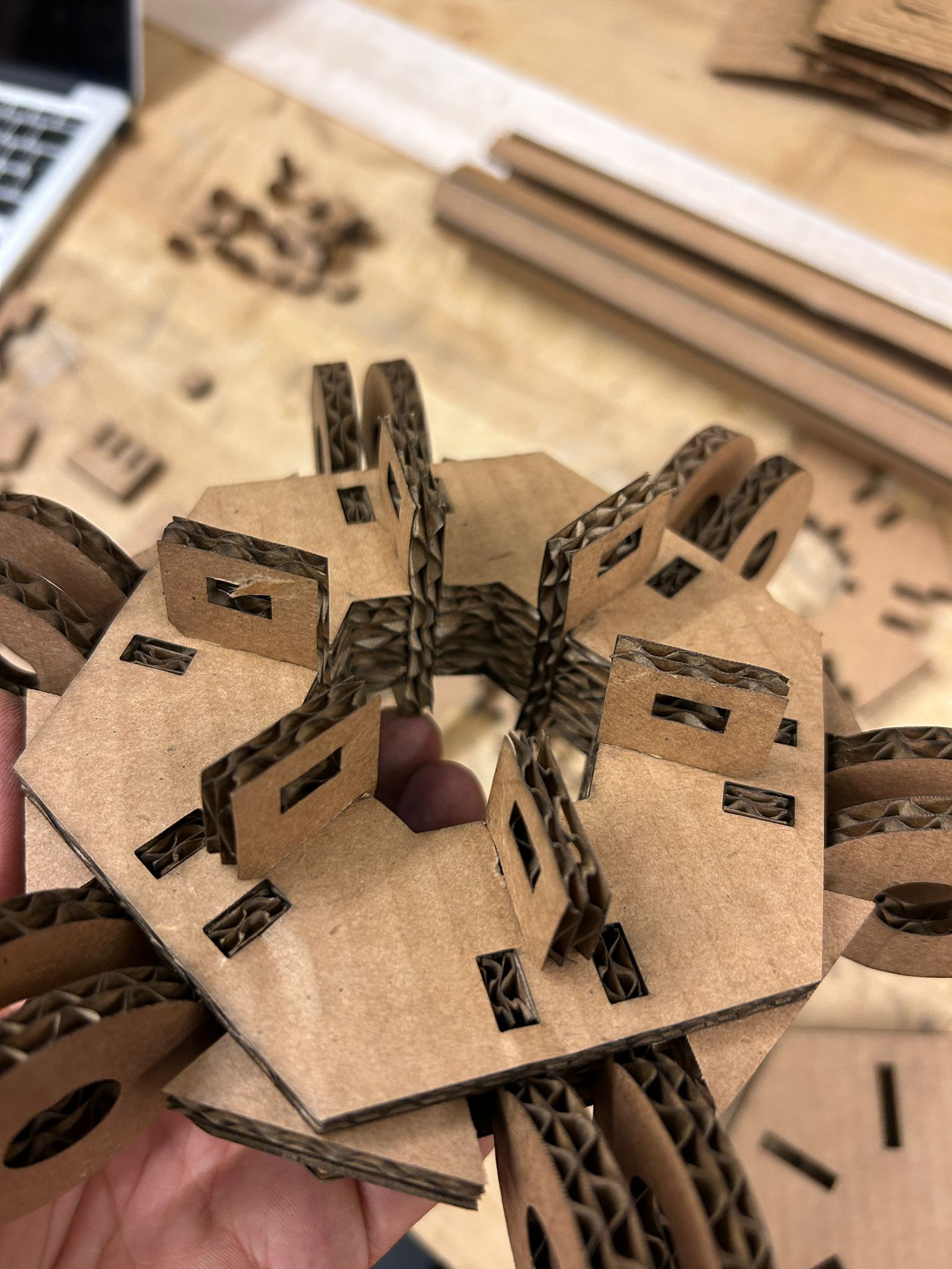
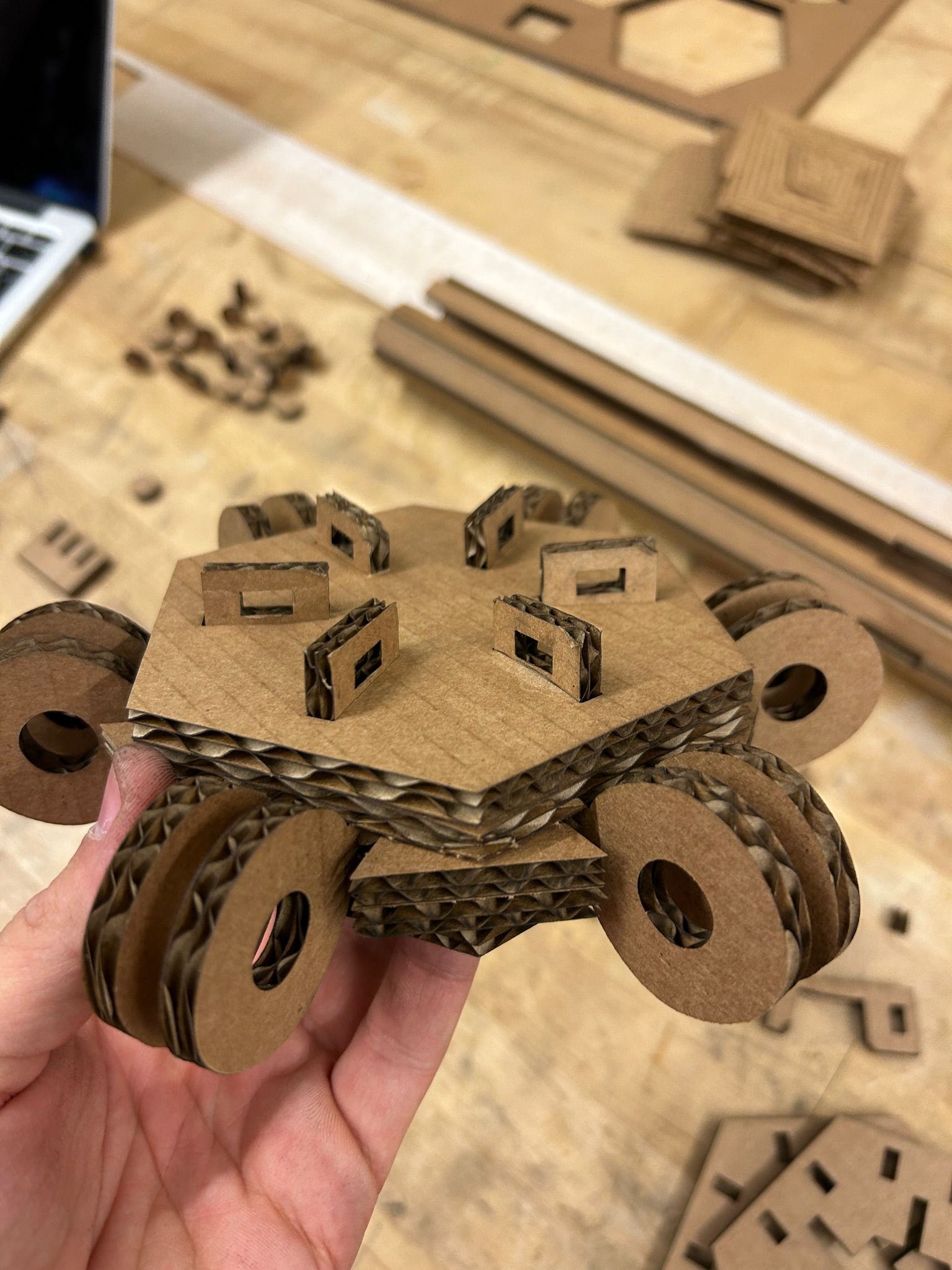
to ensure the integrity of the piece as a whole, the top part is pertruding, another plate added and a smaller piece is locking it in place (not necessary but fun)
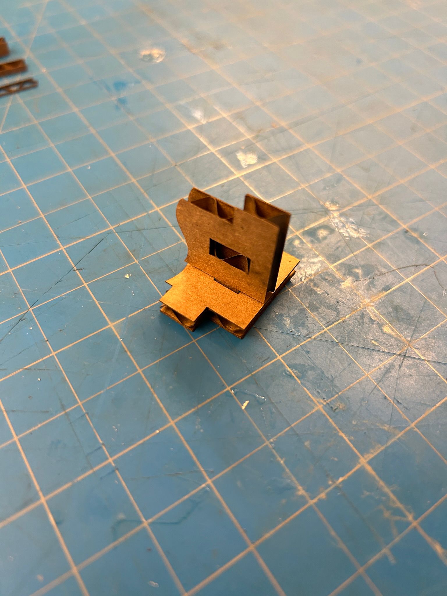
Next i made the individual pieces of the arm. They consist out of two pieces for left and right side, as well as a top and a bottom piece that start and end in a t-shaped component, that latches into the ring of the center piece of the umbrella. these 4 pieces are held together with finger joints as well as two different E-shaped pieces, that hold the left and right side together, and another set that holds the top and bottom piece together. Additionally, the second of the E-shapes also latches internally to the first E-shape, therefore making sure that all the parts cannot come apart again.
the larger top part is basically the same as the shorter one i described earlier, with a ring connector half way through, to allow rotation together with the t-shaped end of the shorter beam.
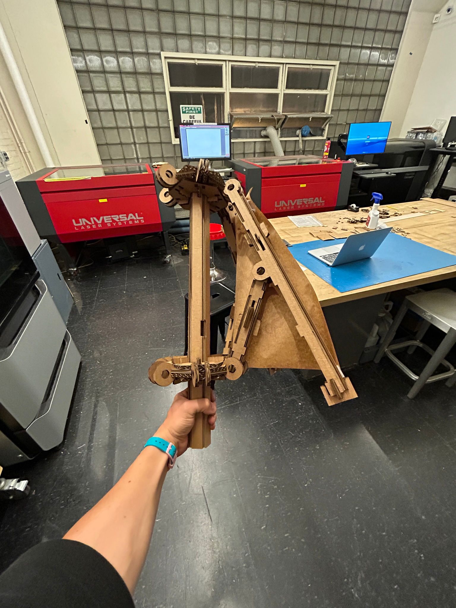
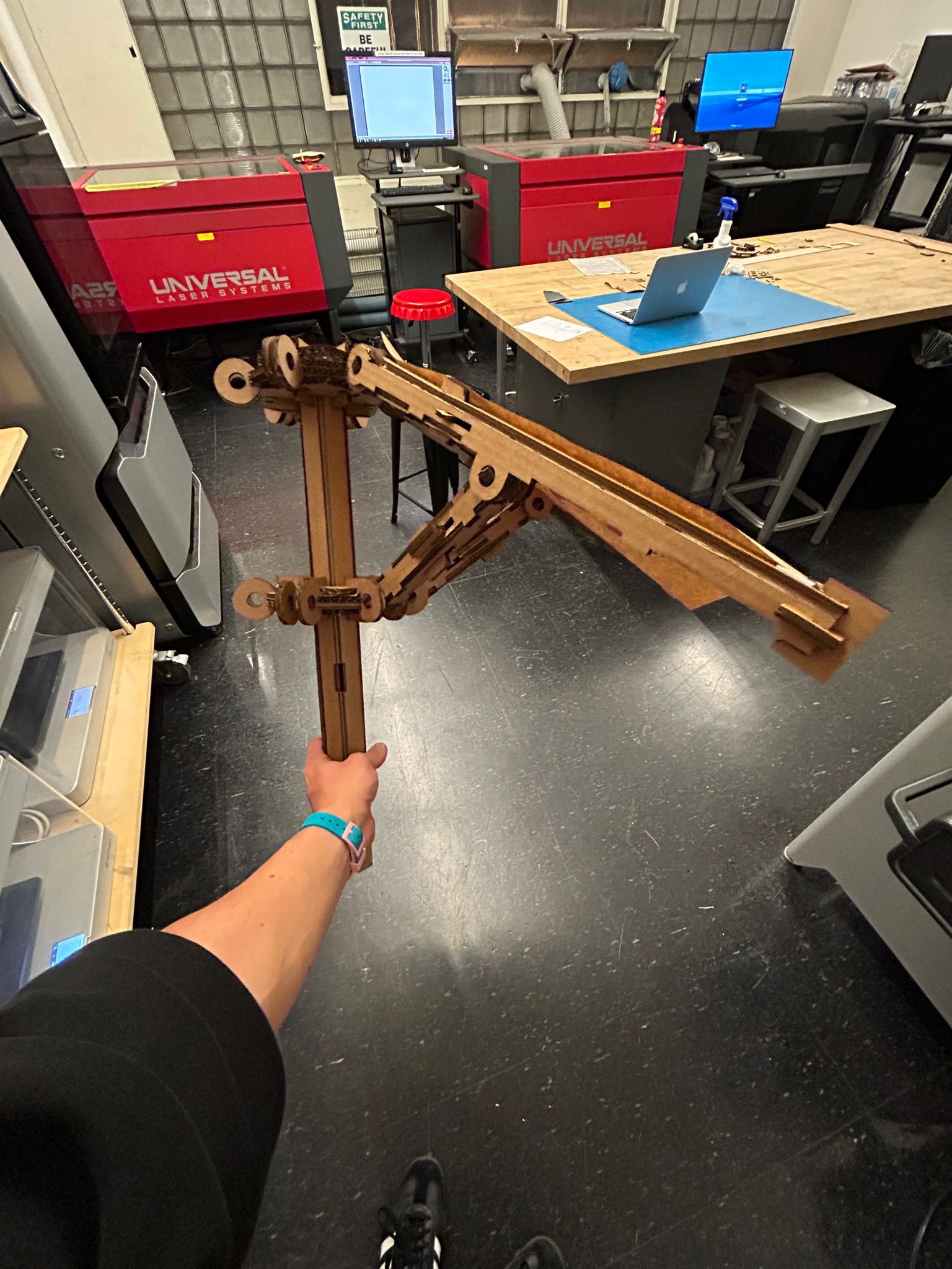
since it took me a while to succesfully put together my own construction idea, i ended up only making 1/6th of the umbrella.. but i hope to achieve the full umbrella in the next few weeks, since the process simply repeats.
ultimately, i hope to make my own transparent lining for the umbrella, but for now, packing paper seemed to be the most appropriate material. to give it a more personal touch, i decided to use a custom vinyl sticker for the packing paper.
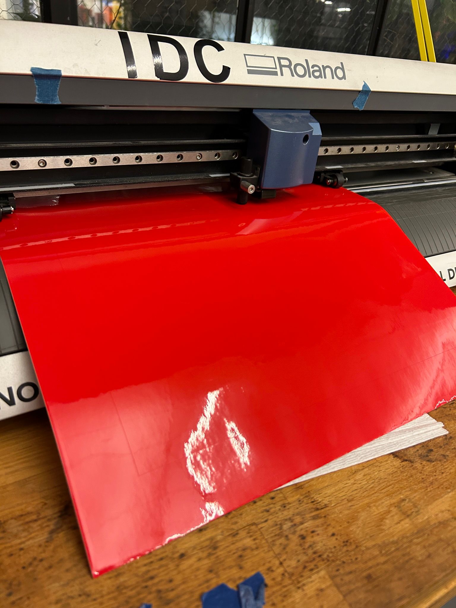
loading the vinyl on the printer was pretty straight forward, one simply lifts the weighted wheels via lever, places the roll behind the machine, and pulls it through, aligning it with the registration mark on the machine, and lowering the weighted wheels again via lever. the wheels can be moved around when lifted to ensure that at least two wheels tough the material at all times (if one has a smaller material). the shop staff informed me that ofter the job is done, one should always lift the wheels again, because having them shut for too long might deform them and cause uneven feeding results in the future.
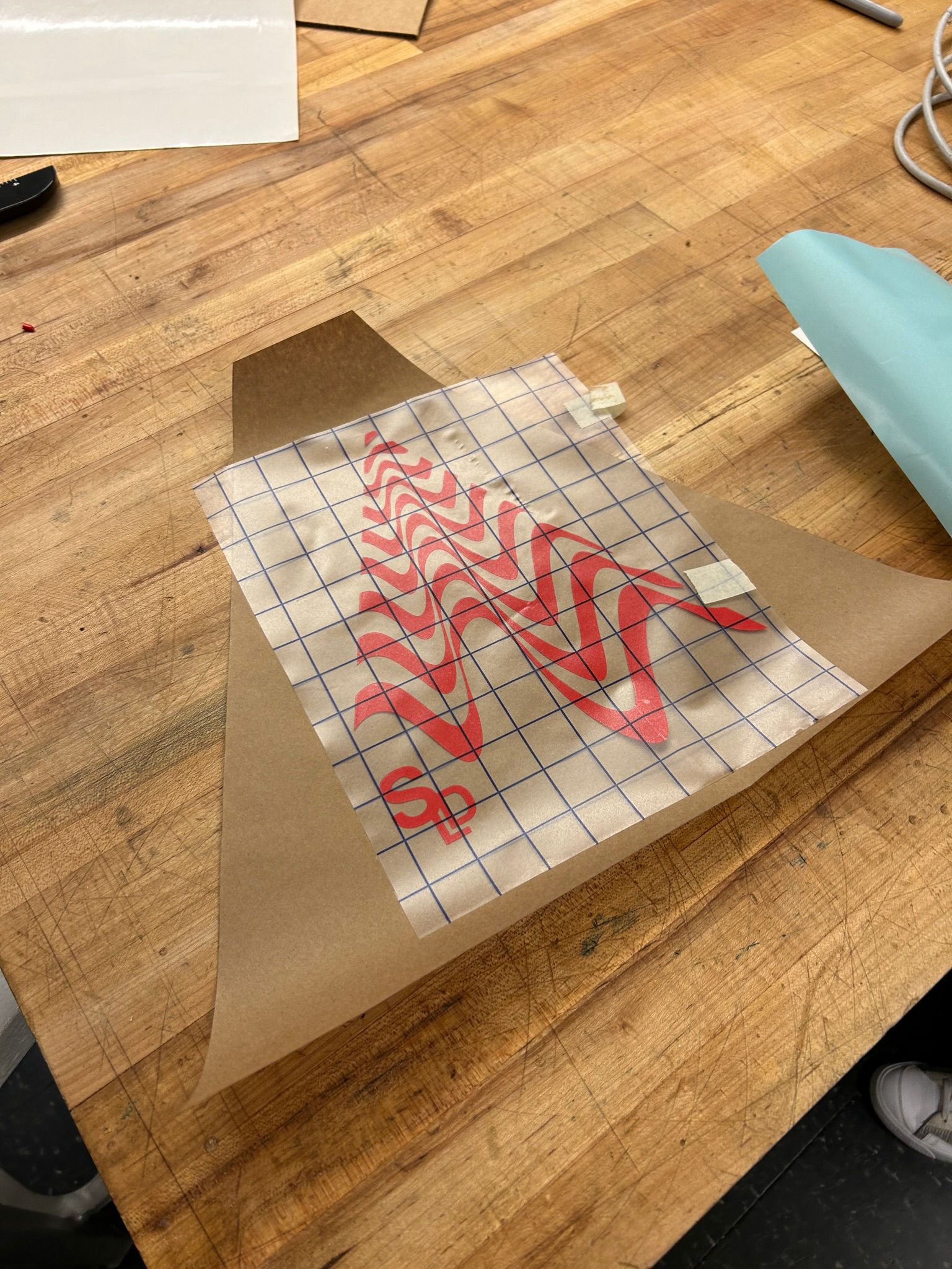
once the print job is done, i cut it off the roll, lifted the wheels and took an exacto blade and tweezers to remove everything from the vinyl that i dont intend to keep from the backing paper. once that was done, i took a sheet of transfer vinyl, placed it on top of my selected vinyl parts and rubbed it carefully, to make sure it would adhere to the transfer material. it is quite interesting, the transfer vinyl must be less adhesive than the vinyl you actually want to stick somewhere, but more adhesive than the vinyl sticks to its backing.
once i had it on the transfer material (which is transparent), i carefully aligned it with the packing material i wanted to use for the umbrella. once again, i rubbed the vinyl carefully, so it would adhere to the paper, and tried not to put too much pressure on the transfer paper where no vinyl was underneath. i was worried that it would stick too much, and once i would try to take it off, it would start ripping the packing paper itself. to my surprise, the transfer paper was sticking to the paper, but not enough to rip it.
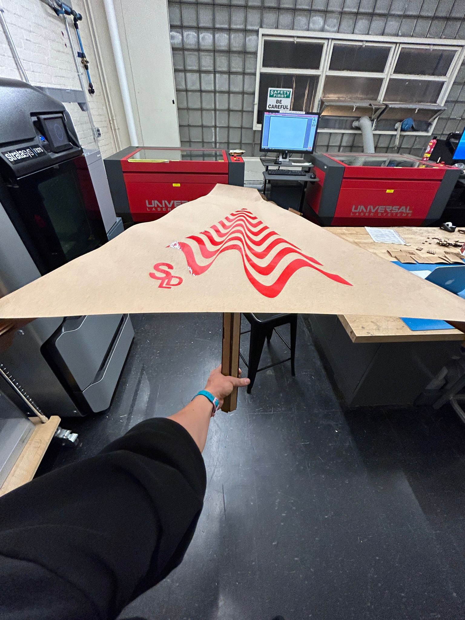
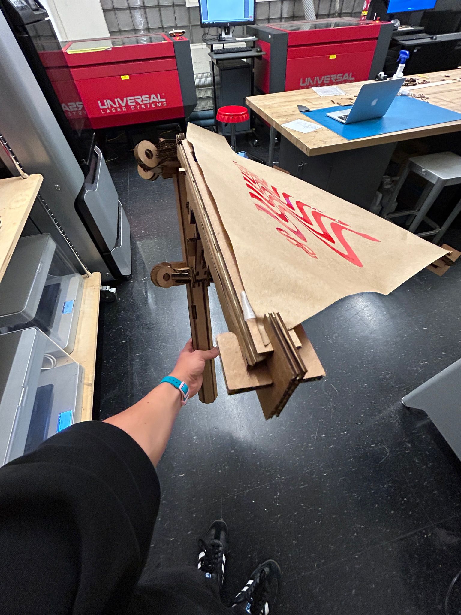
and this is how it looks on my umbrella.
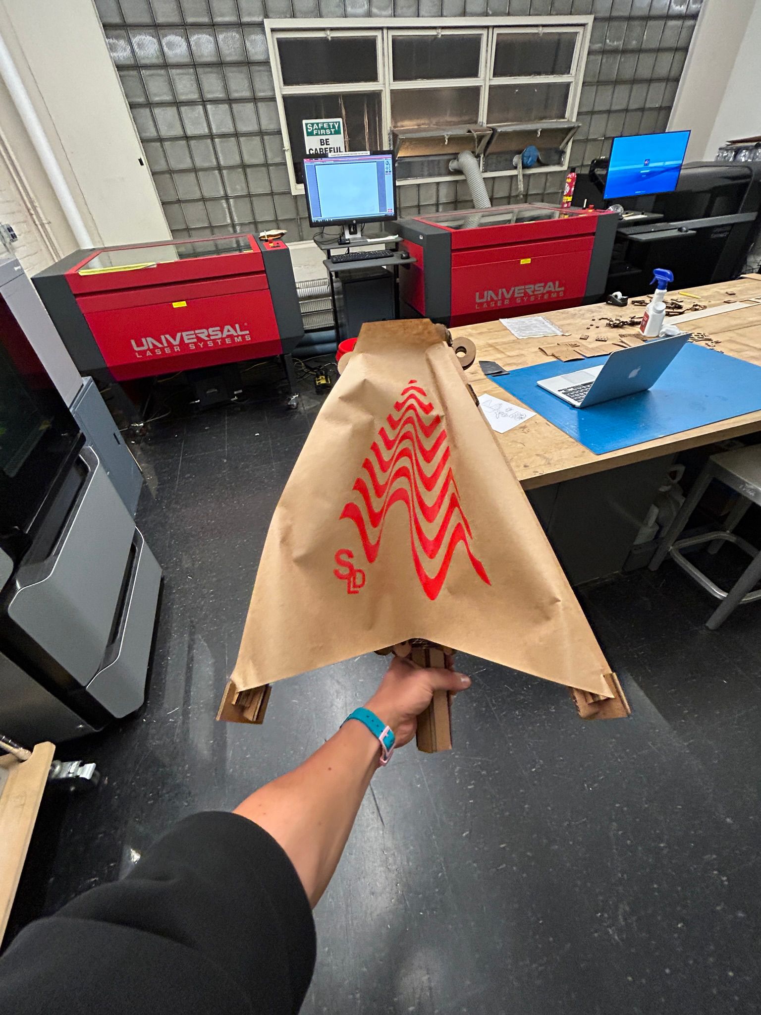
its a few days after laser cutting week, but i just had to finish it. luckily there was some more material in the arch shop, and i was able to repeat the process a few more times to complete the full umbrella.
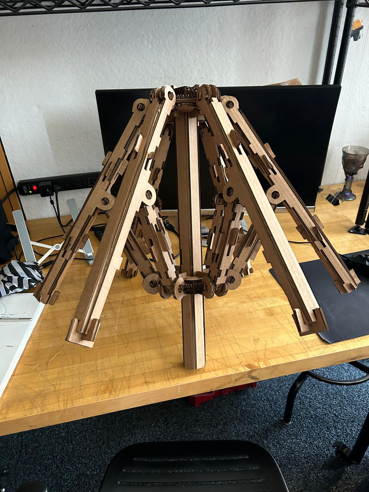
and IT WORKS!!!