#9 gyro out
this week i wanted to look into output devices that are connected to a sensor. I wanted to use a different input device that I have not used before. While playing with a photo resistor last week, i thought it would be interesting in looking into adafruit 9-DOF orientation IMU - BNO085.
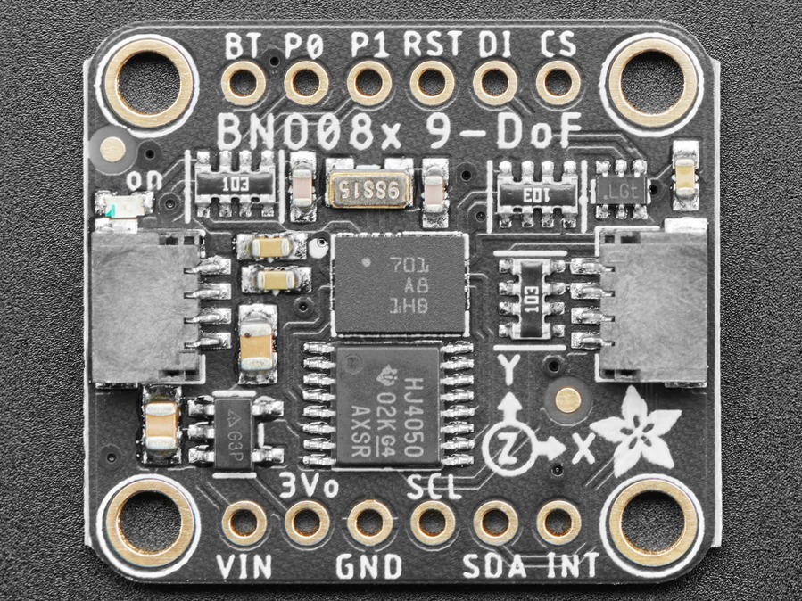
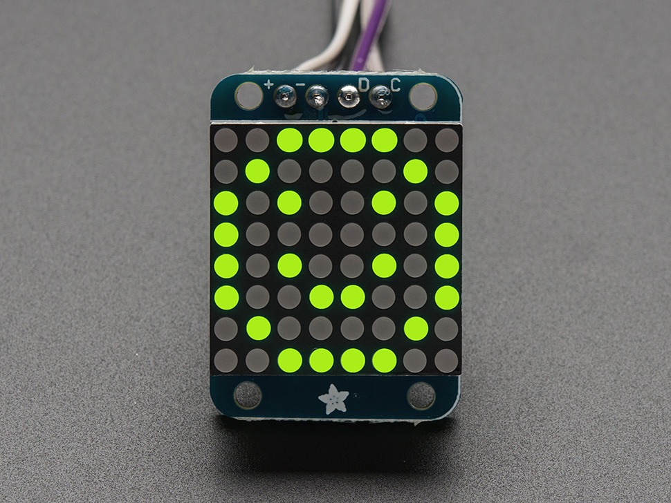
This is a very powerful gryroscope and accelerometer that i hope to connect to a adafruit led backpack - 8x8 matrix. the idea was to make it into a x y level (ignoring the z axis for now). I hope to incorporate it into my final project, where the orientation of my device matters for its operation.
as always, i started by connecting each of the components at the time, install the
respective libraries available for arduino, and look at the example code.
for the adafruit led backpack, it was the adafruit led backpack library and adafruit GFX
library, that come with a "matrix 8x8" example, which give an insight of how to control the device
                    /***************************************************
  This is a library for our I2C LED Backpacks

  Designed specifically to work with the Adafruit LED Matrix backpacks
  ----> http://www.adafruit.com/products/872
  ----> http://www.adafruit.com/products/871
  ----> http://www.adafruit.com/products/870

  These displays use I2C to communicate, 2 pins are required to
  interface. There are multiple selectable I2C addresses. For backpacks
  with 2 Address Select pins: 0x70, 0x71, 0x72 or 0x73. For backpacks
  with 3 Address Select pins: 0x70 thru 0x77

  Adafruit invests time and resources providing this open source code,
  please support Adafruit and open-source hardware by purchasing
  products from Adafruit!

  Written by Limor Fried/Ladyada for Adafruit Industries.
  BSD license, all text above must be included in any redistribution
 ****************************************************/

#include
#include
#include "Adafruit_LEDBackpack.h"

Adafruit_8x8matrix matrix = Adafruit_8x8matrix();

void setup() {
  Serial.begin(9600);
  Serial.println("8x8 LED Matrix Test");

  matrix.begin(0x70);  // pass in the address
}

static const uint8_t PROGMEM
  smile_bmp[] =
  { B00111100,
    B01000010,
    B10100101,
    B10000001,
    B10100101,
    B10011001,
    B01000010,
    B00111100 },
  neutral_bmp[] =
  { B00111100,
    B01000010,
    B10100101,
    B10000001,
    B10111101,
    B10000001,
    B01000010,
    B00111100 },
  frown_bmp[] =
  { B00111100,
    B01000010,
    B10100101,
    B10000001,
    B10011001,
    B10100101,
    B01000010,
    B00111100 };

void loop() {
  matrix.clear();
  matrix.drawBitmap(0, 0, smile_bmp, 8, 8, LED_ON);
  matrix.writeDisplay();
  delay(500);

  matrix.clear();
  matrix.drawBitmap(0, 0, neutral_bmp, 8, 8, LED_ON);
  matrix.writeDisplay();
  delay(500);

  matrix.clear();
  matrix.drawBitmap(0, 0, frown_bmp, 8, 8, LED_ON);
  matrix.writeDisplay();
  delay(500);

  matrix.clear();      // clear display
  matrix.drawPixel(0, 0, LED_ON);
  matrix.writeDisplay();  // write the changes we just made to the display
  delay(500);

  matrix.clear();
  matrix.drawLine(0,0, 7,7, LED_ON);
  matrix.writeDisplay();  // write the changes we just made to the display
  delay(500);

  matrix.clear();
  matrix.drawRect(0,0, 8,8, LED_ON);
  matrix.fillRect(2,2, 4,4, LED_ON);
  matrix.writeDisplay();  // write the changes we just made to the display
  delay(500);

  matrix.clear();
  matrix.drawCircle(3,3, 3, LED_ON);
  matrix.writeDisplay();  // write the changes we just made to the display
  delay(500);

  matrix.setTextSize(1);
  matrix.setTextWrap(false);  // we dont want text to wrap so it scrolls nicely
  matrix.setTextColor(LED_ON);
  for (int8_t x=0; x>=-36; x--) {
    matrix.clear();
    matrix.setCursor(x,0);
    matrix.print("Hello");
    matrix.writeDisplay();
    delay(100);
  }
  matrix.setRotation(3);
  for (int8_t x=7; x>=-36; x--) {
    matrix.clear();
    matrix.setCursor(x,0);
    matrix.print("World");
    matrix.writeDisplay();
    delay(100);
  }
  matrix.setRotation(0);
}
from there it was time to see what the ada BNO085 can do and started by installing the arduino library. first i had the gyro connected via i2c protocol, and used the "adafruit BNO08x" library and rotation_vector example.
                    // Basic demo for readings from Adafruit BNO08x
#include

// For SPI mode, we need a CS pin
#define BNO08X_CS 10
#define BNO08X_INT 9

// For SPI mode, we also need a RESET
//#define BNO08X_RESET 5
// but not for I2C or UART
#define BNO08X_RESET -1

Adafruit_BNO08x  bno08x(BNO08X_RESET);
sh2_SensorValue_t sensorValue;

void setup(void) {
  Serial.begin(115200);
  while (!Serial) delay(10);     // will pause Zero, Leonardo, etc until serial console opens

  Serial.println("Adafruit BNO08x test!");

  // Try to initialize!
  if (!bno08x.begin_I2C()) {
  //if (!bno08x.begin_UART(&Serial1)) {  // Requires a device with > 300 byte UART buffer!
  //if (!bno08x.begin_SPI(BNO08X_CS, BNO08X_INT)) {
    Serial.println("Failed to find BNO08x chip");
    while (1) { delay(10); }
  }
  Serial.println("BNO08x Found!");

  for (int n = 0; n < bno08x.prodIds.numEntries; n++) {
    Serial.print("Part ");
    Serial.print(bno08x.prodIds.entry[n].swPartNumber);
    Serial.print(": Version :");
    Serial.print(bno08x.prodIds.entry[n].swVersionMajor);
    Serial.print(".");
    Serial.print(bno08x.prodIds.entry[n].swVersionMinor);
    Serial.print(".");
    Serial.print(bno08x.prodIds.entry[n].swVersionPatch);
    Serial.print(" Build ");
    Serial.println(bno08x.prodIds.entry[n].swBuildNumber);
  }

  setReports();

  Serial.println("Reading events");
  delay(100);
}

// define the sensor outputs you want to receive
void setReports(void) {
  Serial.println("Setting desired reports");
  if (! bno08x.enableReport(SH2_GAME_ROTATION_VECTOR)) {
    Serial.println("Could not enable game vector");
  }
}


void loop() {
  delay(10);

  if (bno08x.wasReset()) {
    Serial.print("sensor was reset ");
    setReports();
  }

  if (! bno08x.getSensorEvent(&sensorValue)) {
    return;
  }

  switch (sensorValue.sensorId) {

    case SH2_GAME_ROTATION_VECTOR:
      Serial.print("Game Rotation Vector - r: ");
      Serial.print(sensorValue.un.gameRotationVector.real);
      Serial.print(" i: ");
      Serial.print(sensorValue.un.gameRotationVector.i);
      Serial.print(" j: ");
      Serial.print(sensorValue.un.gameRotationVector.j);
      Serial.print(" k: ");
      Serial.println(sensorValue.un.gameRotationVector.k);
      break;
  }

}
so i tried to connect it via UART connections, and needed to install the adafruit BNO08X RVC and played around with the example "uart_rvc"
upon realization that my pcb was broken and useless, since I was not able to
connect anymore to the SDA and SCL (I2c pins), i decided to go back to the
"beloved" breadboard. at first, i wanted to connect the sensor via I2c to the seeed xiao rp2040
but realized that the pixel matrix would also need to be connected to these pins.
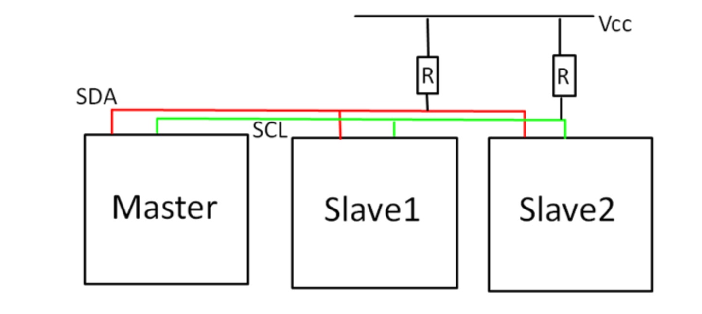
i did not think about the fact that SDA and SCL connections are bus connections that
would allow multiple devices to be communicated at the same time, since it requires the specific
address of the components, and can therefore address them by themselves, even if they are
connected through the same pins (for more information about this read this article article and this simple example)
(i really hope this antiquated and problematic naming convention for communication protocols will change soon -- for more information, see this article)
since i read this too late, i resorted to connecting the gyro via another communication protocol,
that i have not used yet. i ended up connecting it via UART connection,
using the RX and TX pins to connect to the microcontroller.
the resulting level, was semi-satisfying for many reasons. for one, some of the connections
were very flimsy and seem to be unstable, especially the UART connection to the gyro sensor.
things that i identify as issues are:
- the breadboard and jumperwire connections that are not stable
- the UART connection that is limited to 9-bit transmission at the time
- the UART connection is generally slower than the i2c communication
i would love to rebuild my pcb, connect the sensor and matrix through it, and put
them on top of each other, so that using the contraption would feel more natural.
i hope to build a case for it and implement it all with a battery. -- stay tuned --
this is the code i worte/pieced together for this:
                #include
                    #include
                    #include
                    #include "Adafruit_BNO08x_RVC.h"

                    Adafruit_BNO08x_RVC rvc = Adafruit_BNO08x_RVC();

                    #define MATRIX_WIDTH 8
                    Adafruit_8x8matrix matrix = Adafruit_8x8matrix();

                    void setup() {
                      // it will take a while to open the serial monitor
                      Serial.begin(115200);
                      while (!Serial)
                        delay(10);

                      Serial1.begin(115200);
                      while (!Serial1)
                        delay(10);

                      if (!rvc.begin(&Serial1)) {
                        while (1)
                          delay(10);
                      }

                      matrix.begin(0x70);
                      matrix.clear();
                      matrix.writeDisplay();

                      // Print labels for the values
                      Serial.print(F("Yaw"));
                      Serial.print(F("\tPitch"));
                      Serial.print(F("\tRoll"));
                      Serial.print(F("\tX"));
                      Serial.print(F("\tY"));
                      Serial.println(F("\tZ"));
                    }

                    void loop() {
                      BNO08x_RVC_Data heading;

                      if (!rvc.read(&heading)) {
                        // data not available -- keep trying
                        return;
                      }

                      Serial.print(heading.yaw);Serial.print(F(","));
                      Serial.print(heading.pitch);Serial.print(F(","));
                      Serial.print(heading.roll);Serial.print(F(","));
                      Serial.print(heading.x_accel);Serial.print(F(","));
                      Serial.print(heading.y_accel);Serial.print(F(","));
                      Serial.print(heading.z_accel);
                      Serial.println("");

                      // X and Y values to matrix coordinates
                      int x = map(heading.x_accel, -10, 10, 0, MATRIX_WIDTH - 1);
                      int y = map(heading.y_accel, -10, 10, 0, MATRIX_WIDTH - 1);


                      matrix.clear();

                      // Draw pixel
                      matrix.drawPixel(x, y, LED_ON);


                      matrix.writeDisplay();

                      // delay between update
                      delay(10);
                    }