#13 tries to get 24 frames
setting up this weeks robot class, I found watching this video very helpful
to understand the components and how the plugin for the UR10 works.
there are two ways to set up the code for the robot, one through python, one through grasshopper.
personally, I often find that the node based grashopper interface helps me better understand initial motivs
and operations, so I went to use that method. see Robots plugin for grasshopper here or also through grasshoppers internal library.
here i want to thank Danny for helping me out in understanding how to set up the UR10
grasshopper simulation and how to run the files. due to the many students using the robots at the same time, i resorted to using the ur10 robot arm in the Self Assembly Lab. Thank
you to everyone that enabled me to use their robot during this week!
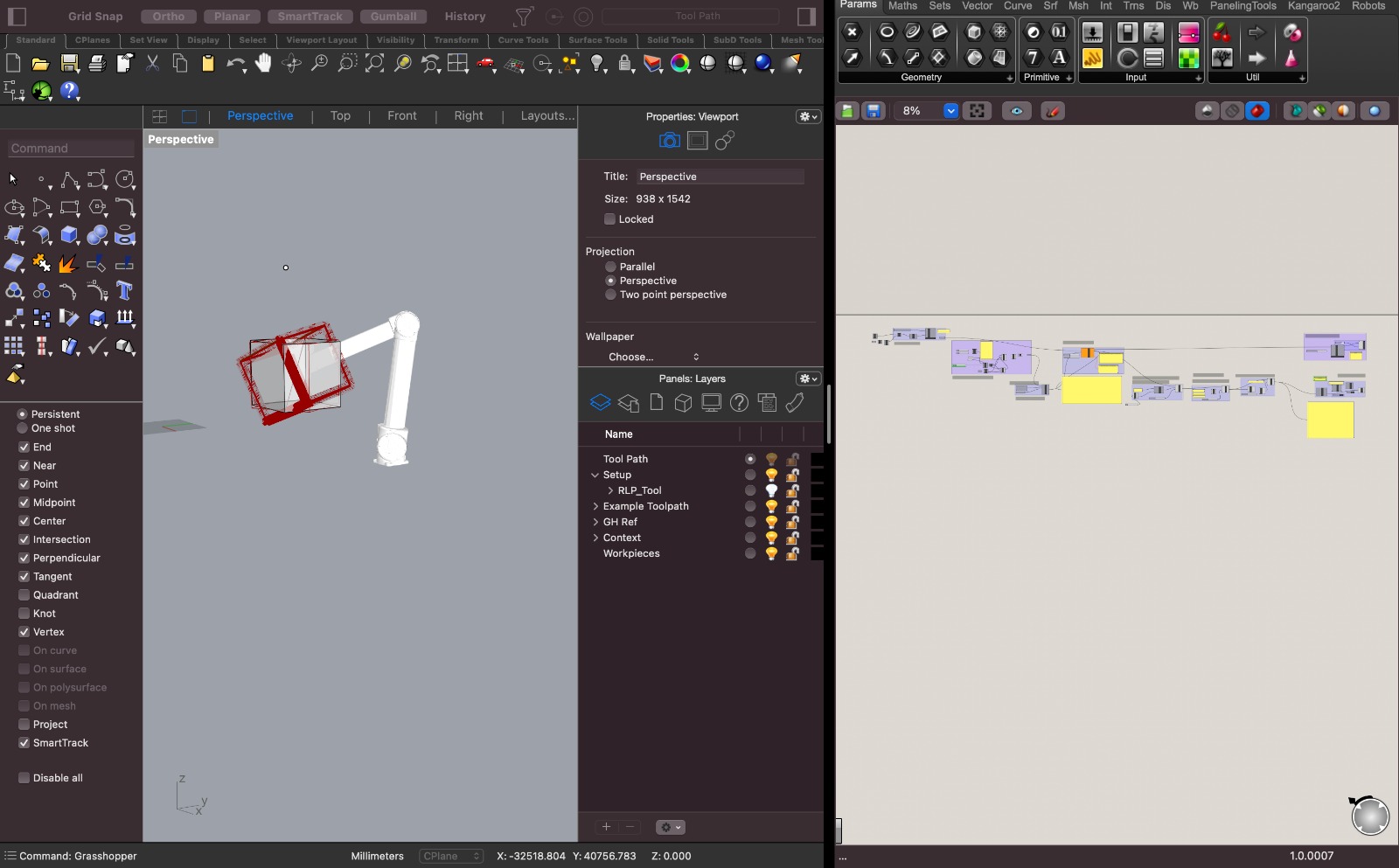
to start things off, i used Grasshopper for Rhino3D 7. i have been using rhino and
grasshopper for a couple of years and have been familiar with the interface and the controls of the software and the plugin. after installing the Robots plugin for grasshopper
it was time to definethe robot
i was able to set up the robot with the "load robot system" element and selecting a library, one could make a new library, but the bartlett school has already set one up using the UR10 robot arm, which is the one i ended up using the only additional thing i ended up doing is making my own plane in rhino with a curve to define the origin base location of the ur10, in case i ever wanted to move the robot arm into a different relative location, i would be able to change the plane input for its location. once we do that, we should see the robot's geometry in the perspective viewport in rhino.
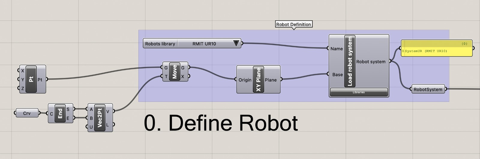
after playing around both with the hend held terminal of the robot arm as well as the individual controlls i was able to set for each joint of the robot, i drew a 40x40x40cm square
in rhino, placed it in front of the robot and extracted only the edges of the cube and made them into lines (using the "dupedge" command in rhino).
afterwards i defined a two axis rotation of the cube and defined the rotations into steps. i ended up finding a sweet spot in between the degrees/step for both
rotation axis, so that the cube would be back in its original rotation after 24 steps respectively.
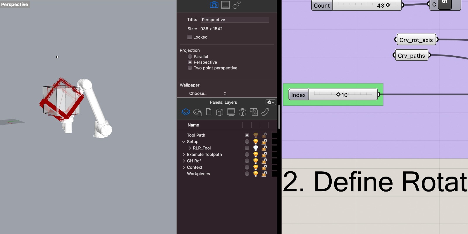
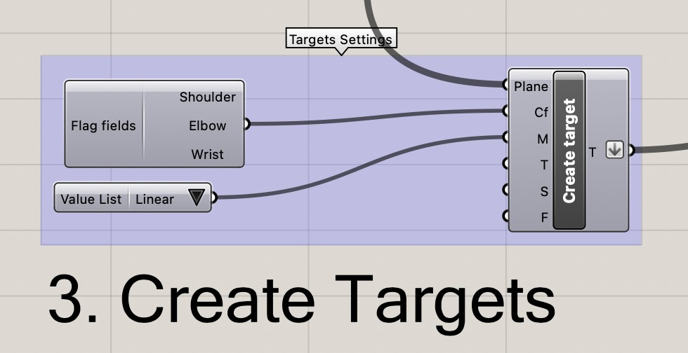
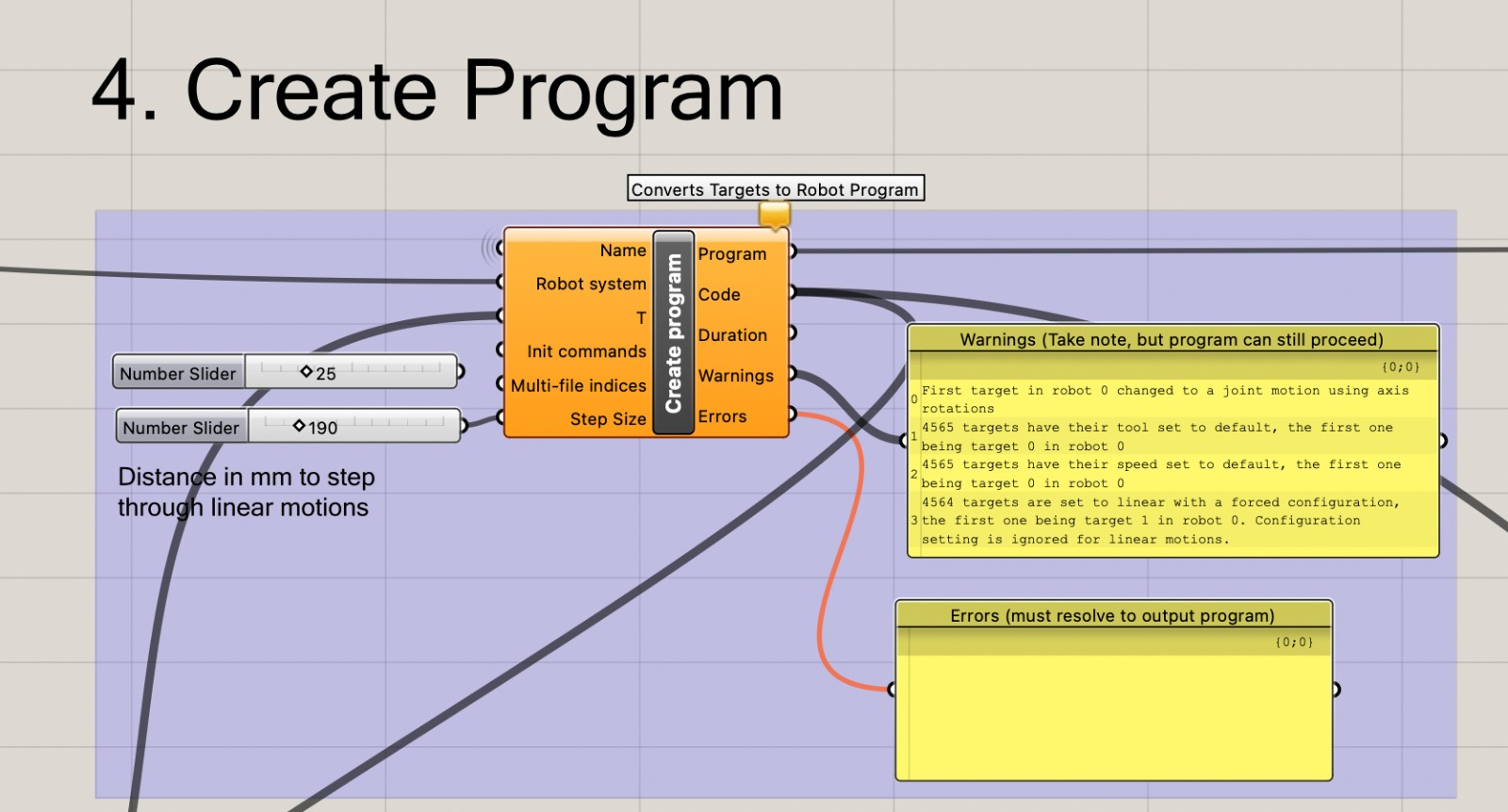
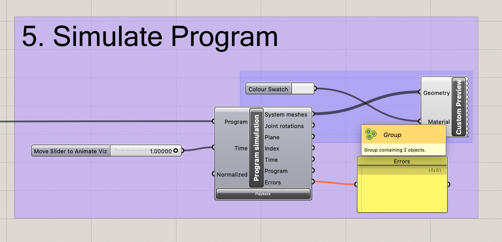
i created a targe control that would control how the robot's simulation would go about following my line inputs and found that "linear" was the smoothest and most "natural" motion of the arm. further down in "5. Simulate Program" i added a number slider to the simulation component, that would allow me to preview the entire tool path of the robot by sliding in between 0 and 1, checking if the robot can reach all the points and whether it is able to follow the paths.
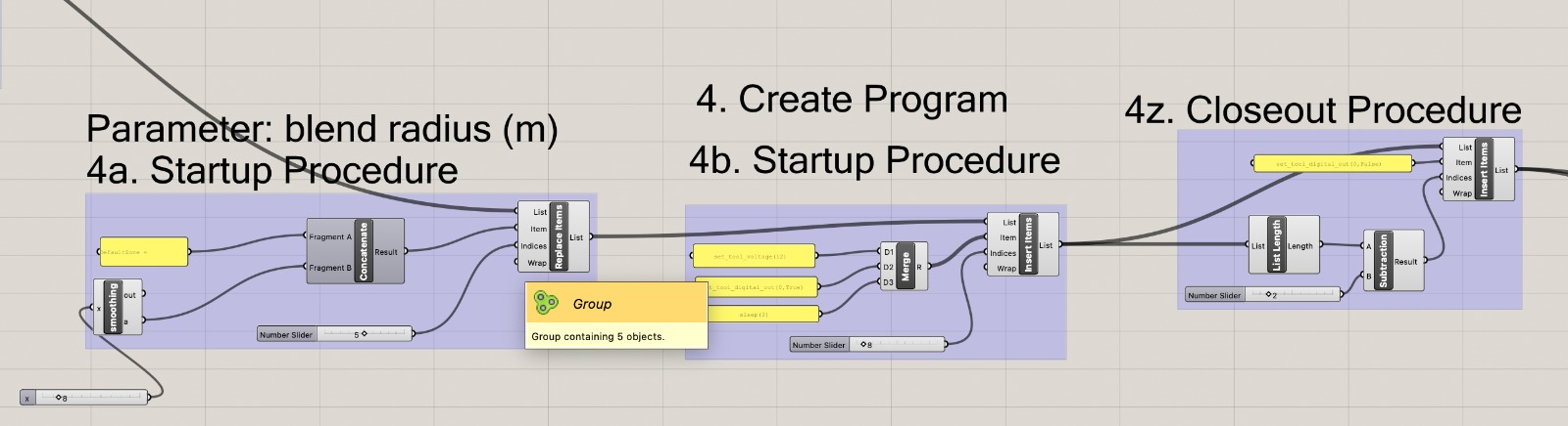
i created a "create program" component that would set all the individual targets into a list of commands and followed the above tutorial to create the setup procedure.
to follow the steps and the file in more detail check out my SLD_LightDrawing.gh file that i used for this
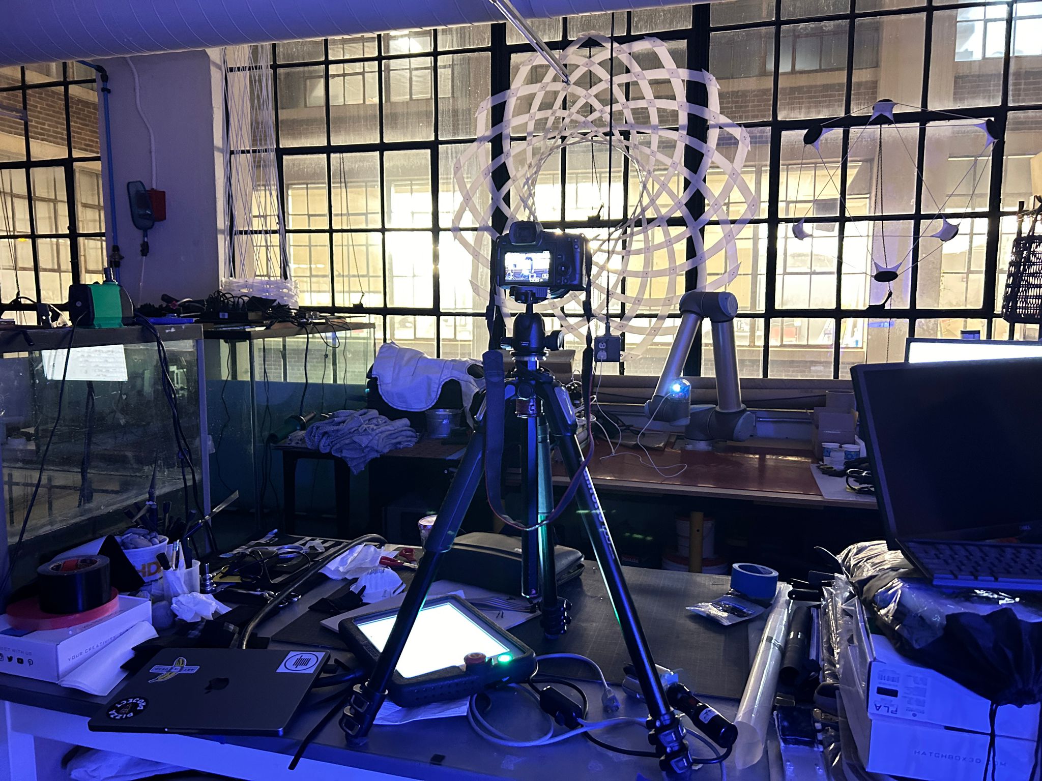
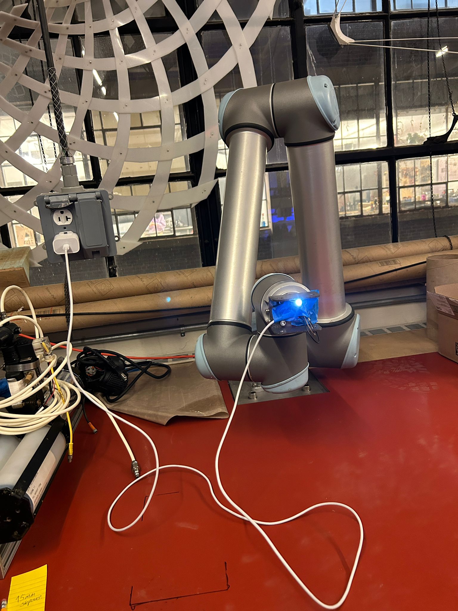
after i was satisfied with the simulation, i was able to export the first file, loaded it on a usb-thumb-drive and plugged it into the control terminal of the robot, running it for the first time. I had to go back and forth a couple of times, adjusting the location of the cube, before it was oriented and situated in the right orientation relative to the space i was working in. i hooked up a simple led light to the robot, blocked redundand light off by using masking tape and ran a couple of tests.
after i was satisfied with the toolpath of the first cube, i went back into grasshopper and exported a different path file for the robot for each of the 24 frames (see download of the first robot path here). since i did not know how to connect my microcontroller to the robot with the tools i had available at the time, i had to work with a continuously lit led, and therefore designed the toolpath in such a way that it actually draws a couple of edges twice, to complete the cube without making diagonales in between the edges.
find all the different robot paths for each of the frame here: Download DrawingPaths
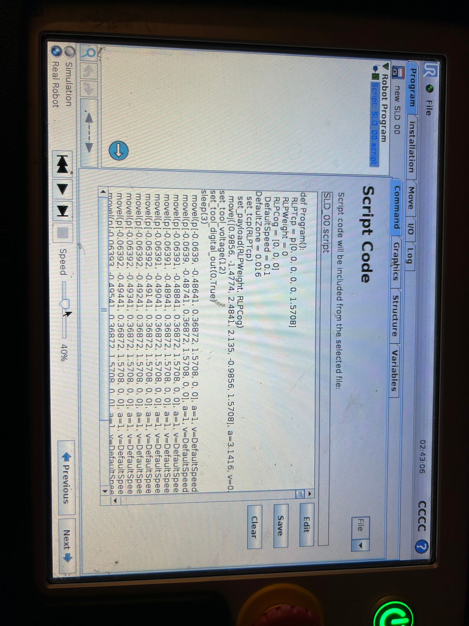
every so often (approximately every 5 paths) i would get an error code like this on the screen, and had to restart the robot, load the file again, and it would work on the next try. i have not been able to find out exactly why that is the case.
it took many more than 13 tries to actually make all the things work. the script i used to autmatically export the simulated path as code onto my usb stick seemed to struggle
sometimes after i moved to the next step in grasshopper and it seemed to skip some of the different code parts or save the same one twice. eventually i got all the 24 tool-paths
exported and loaded onto the thumb drive, was able to set up a camera on the table adjacent to the robot and set it to the "bulb" function. the dslr i used for this
did not allow me a long time exposure over 8 seconds, but each of the tool-pathts took the robot approx. 49sec to complete, the only function that would allow me to do a long-time-exporsure
for that long is the "bulb" function, which is a manual setting (used to be a physical one in analog cameras) that would keep the shutter of the camera open for as long as the
shutter button is held... so i ended up starting the tool-path on the terminal, walking to the camera, and holding the button for the entire time of the robots movement, before
going back to the terminal, loading the next path etc. etc. etc.
after the final path, i would end up with 24 different photos, showing the 3d cube in different orientations, in the future i would like to experiment with a second aligned robot arm that would
control the camera, and would be able to advance the camera's position in relation to the 3d light drawing for each step of the animation. but for now i had a static shot of the camera for each
frame of the video. i brought the images into Adobe After Effects, but Photoshop, Premier and other video editing software would work
just as well for this purpose. The key is to have the images' name with numbers in succession at the end, digital cameras do this by default, where one file is called something like "BN00023" and
the next photo one would take would be called "BN00024" and so forth. when importing files into a video editing software, one can select the first file and the software recognizes the naming convention
as a pattern of succeeding images, and can load them as a sequence. since the human eye can identify seamless motion graphics around 23 framse per second, and i had 24, i started with a one second animation. while
this was a good idea in the beginning, it soon turned out to be moving too fast, so i turned the frames/second down to about 12, which gave me a 2sec video/revolution.
to make the video play longer, i copied the animation and added the copy to the end of the original and reversed the speed by -100% in the "time stretch" function, this would play the file
in reverse. this was only possible because the orientation of the first cube of the animation was the same as the last one etc.