#14
GRAFFITI ROBOT
inspiration
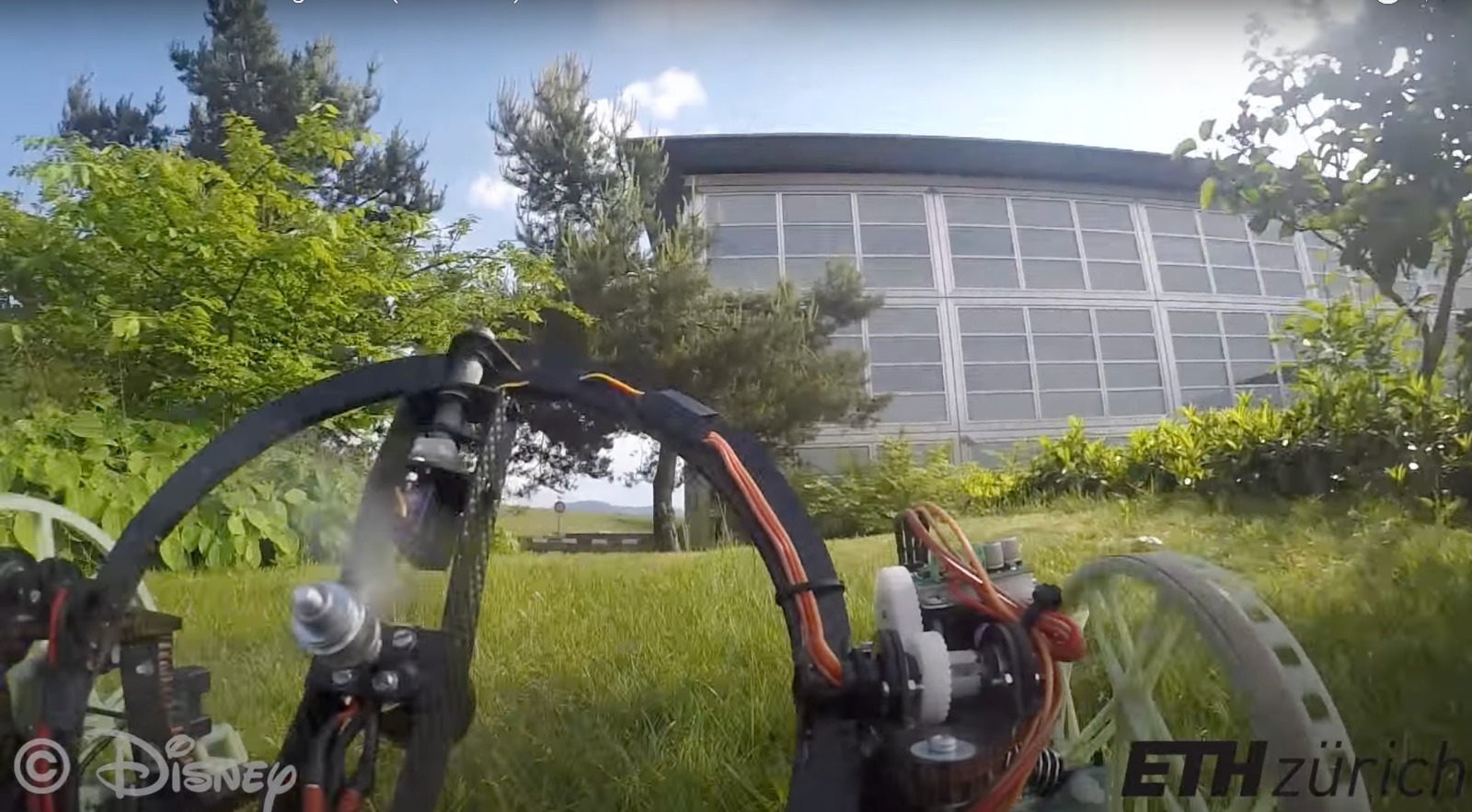
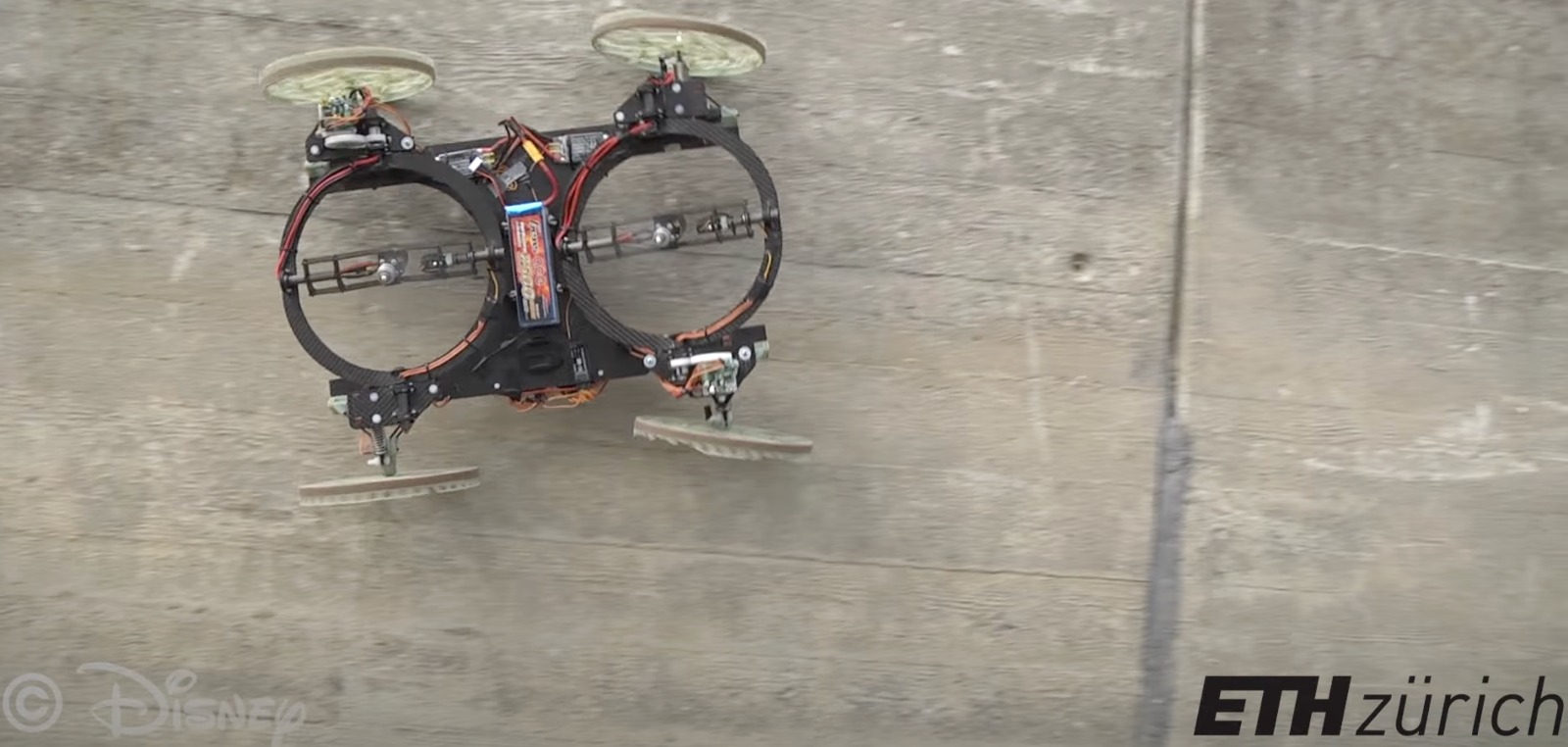
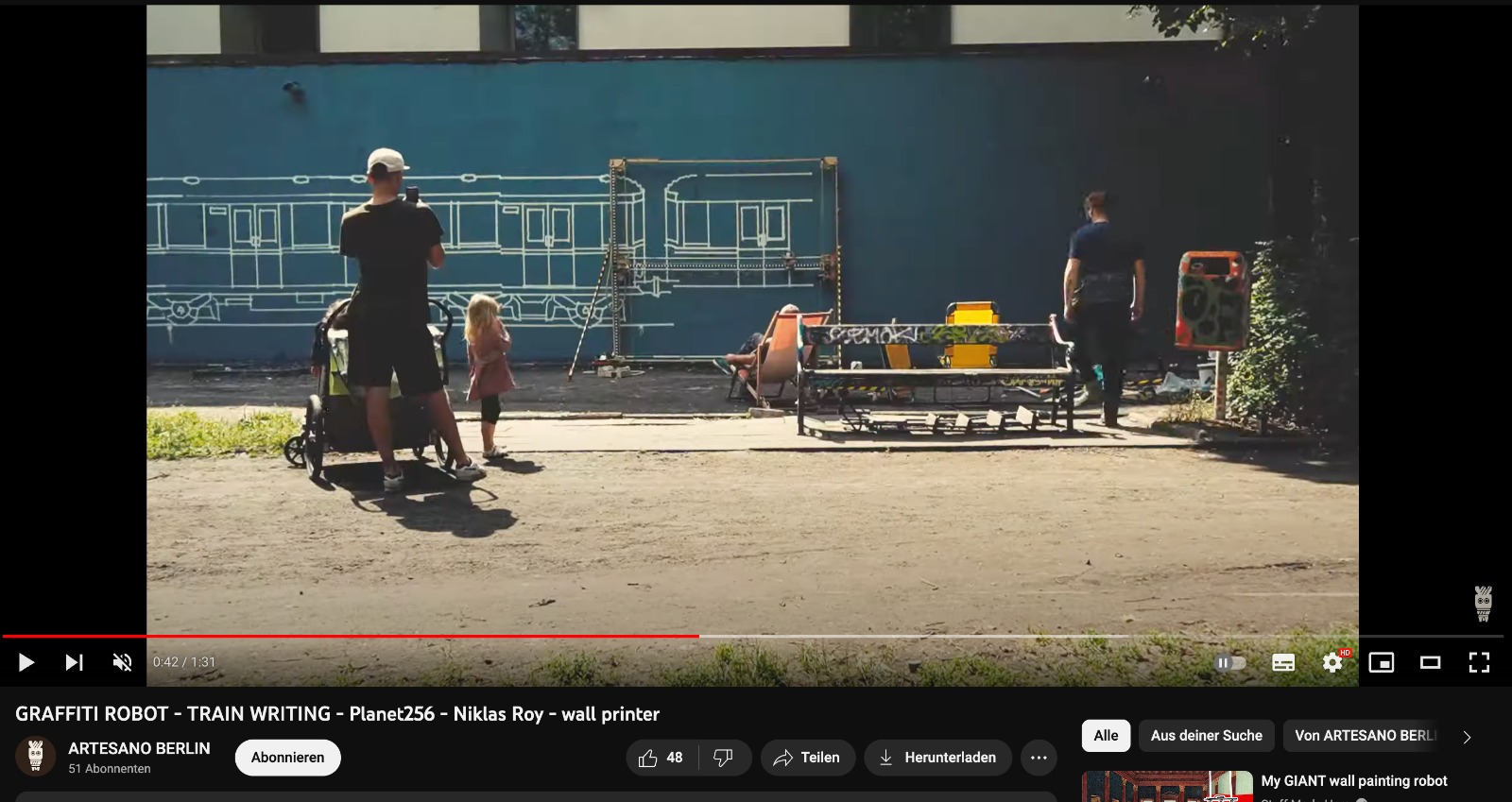
there have been a number of projects that inspired my idea. one of the most influential ones is the vertigo robot from the eth together with Disney, where they made a wall climbing robot that is completely propelled by two rotating drone motors. the friction with the ground and/or the wall it is driving on allows the fron wheels to steer the robot.
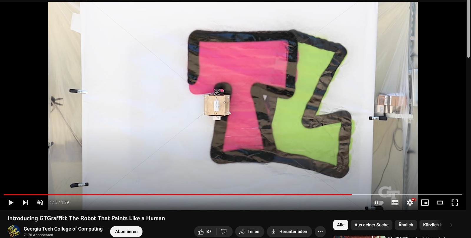
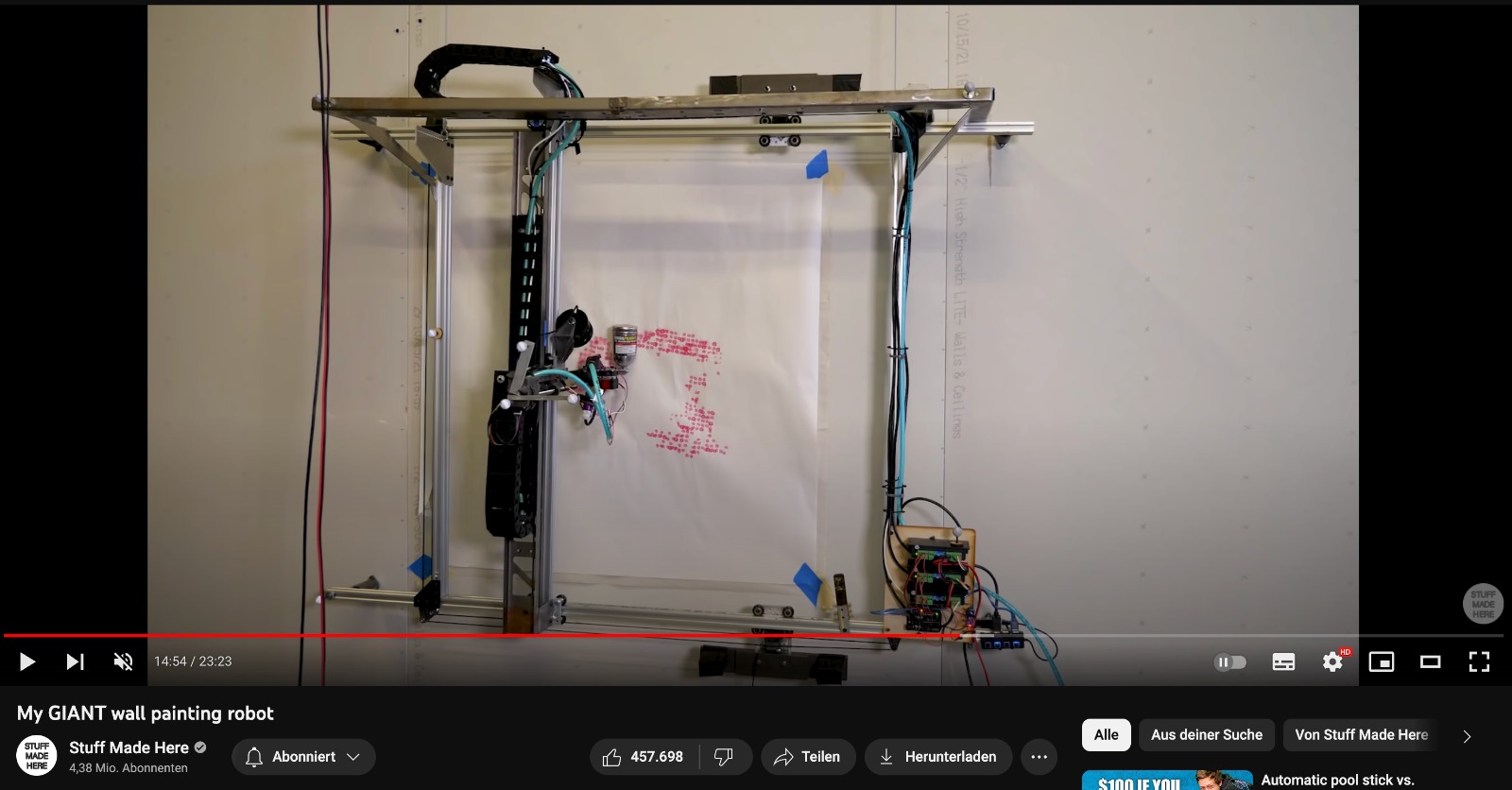
other projects have experimented with graffiti robots, but always require a gantry attachment to the wall, or at least a wire that is attached to the top of the wall to control the location of the robot.
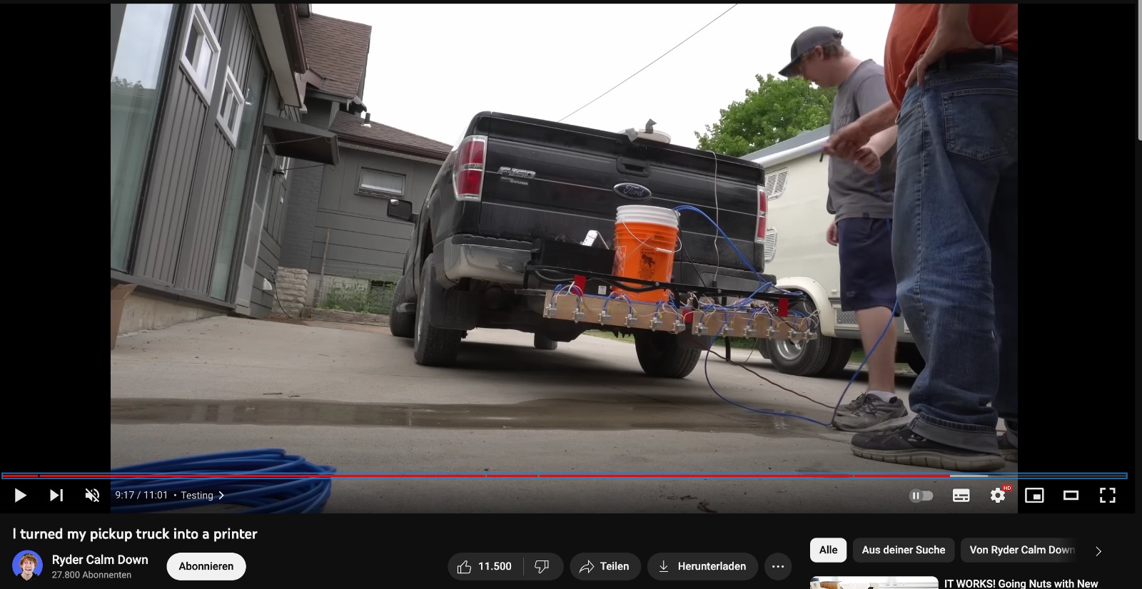
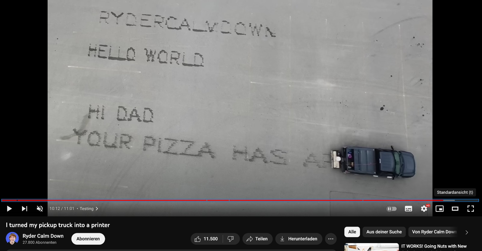
besides spray cans, i have seen this video below, where different nozzles are opening and closing, making a dot matrix of dibbling water, allowing the car to write messages with water on the pavement while driving.
somewhere in between these ideas lives my final project, where i hope to achieve a graffiti robot, that does not require any additional support to paint on the wall.
development
to start things off, i have been thinking about the way to approach this project.
it seems best to spiral my way towards the wall driving spray robot:
1. make a rc cars that drive on the ground
2. add an actuated pen to the ground driving vehicle
3. trying to load a vector file to the robot and have it draw the respective g-code
4. learning how to actuate the spray can
5. adding a spray can to the ground vehicle and drawing an image
6. taking what i learned and making a simple wheeled car to drive on walls using drone motors and blades
7. cutting weight and implementing the spray can mechanism
8. remote controlling the vehicle and loading a g-code file
9. figuring out how to track the vehicle on the wall if necessary for the drawing component
the basic principle is a 4-wheeled robot, each wheel individually controlled, using omnidirectional wheels to control the drawing portion of the robot. To push the robot against the wall, i hope to use 2 or 3 drone fans, that, if they are able to deliver enough thrust, can allow the wheels to actually navigate the robot itself. previous experiments with gyro sensors might allow me to turn the fans on, when the robot is vertical (otherwise turn off).
additionally, i was hoping to use a solenoid or servo motor to trigger the spray can to spray or release to stop the paint flow (see reference video be 'The Practical Engineer' here).
from personal experience with spraycans, the ideal state of the can is to have it positioned parallel to the wall, at a fixed distance to limit the line thickness (other than with different caps) and have it be oriented perpendicular to the ground, to allow it to use as much liquid as possible (upside-down cans will stop at a certain point).
the solution to this would be to have the can in its own bearring loaded ring, that, through the weight of the can, would use gravity to orient the spraycan at all times, regardless of the vehicles orientation.
for the wheels i want to use, i am still in between omni and mecanum wheels.
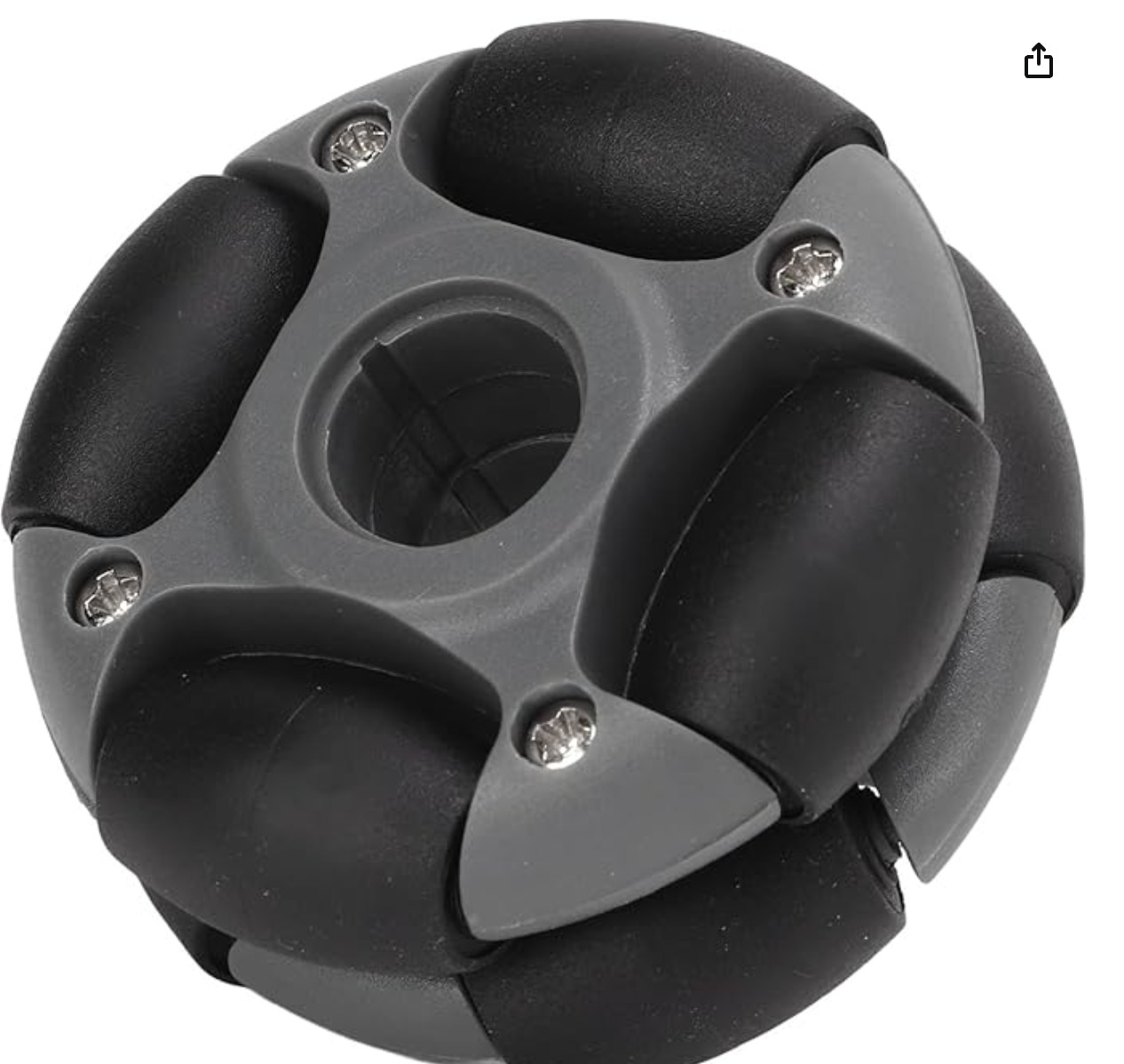
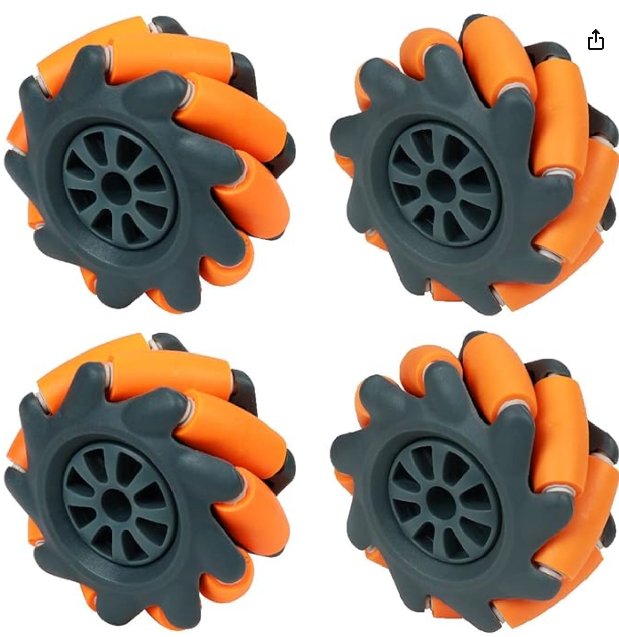
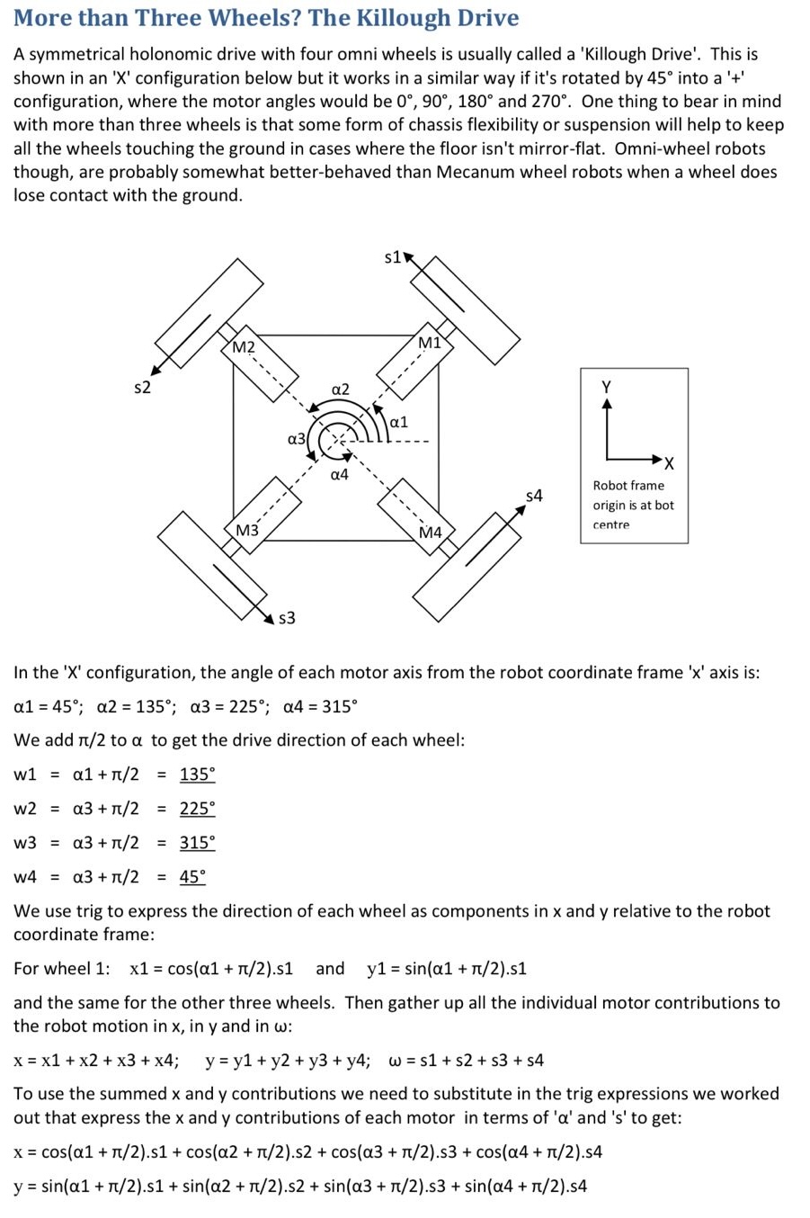
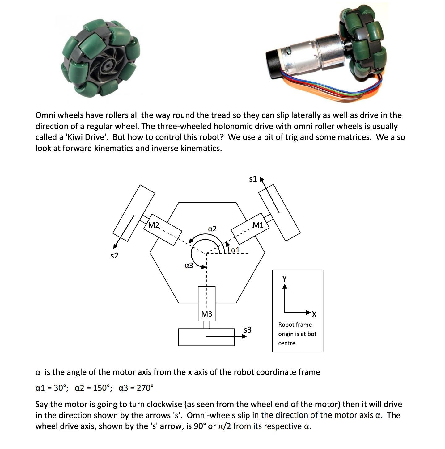
if i go with the omni wheels i found this article that explains the different configurations and calculations for 2, 3, 4 or more wheel settings, that would be useful when setting the movement directions in the code, to controll each of the wheels individually.
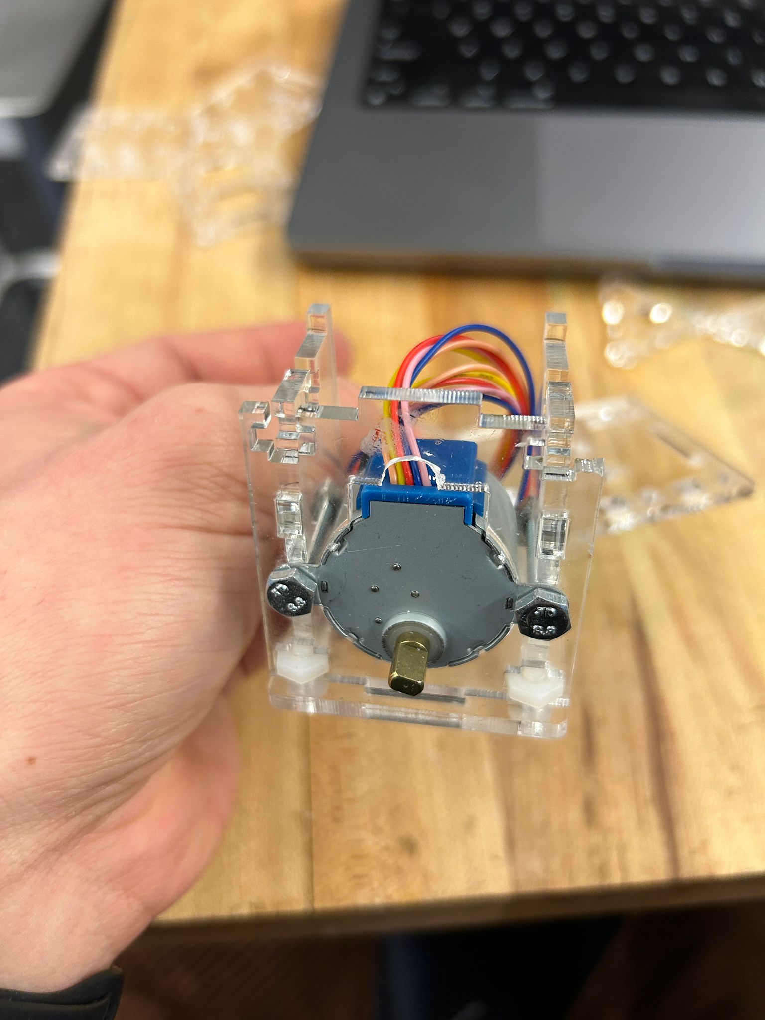
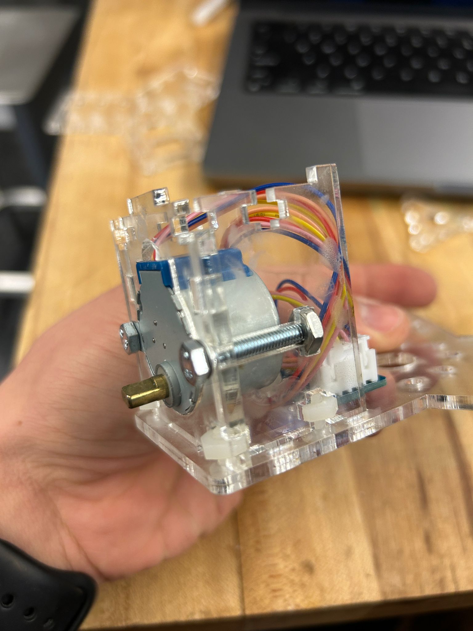
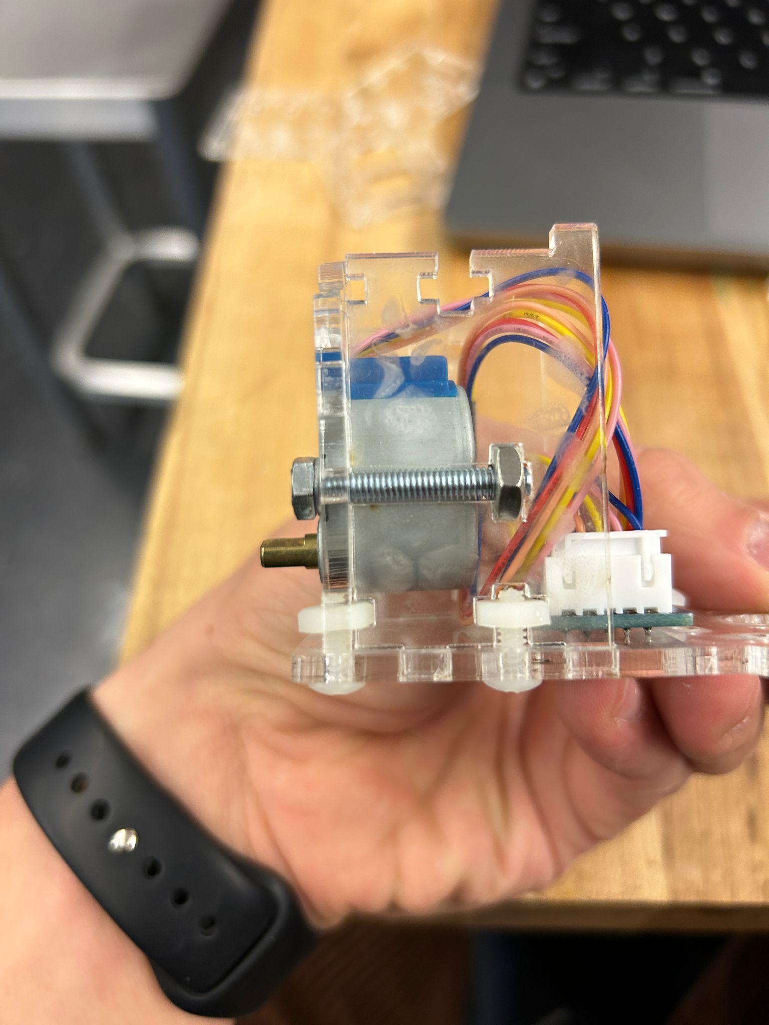
i ended up experimenting with ways to mount the 28BYJ-48 geared stepper motor into an acrylic housing, using the laser cutter, and a screw-bolt notching system, that would allow me to put different components vertically into each other and tighten them without any glue
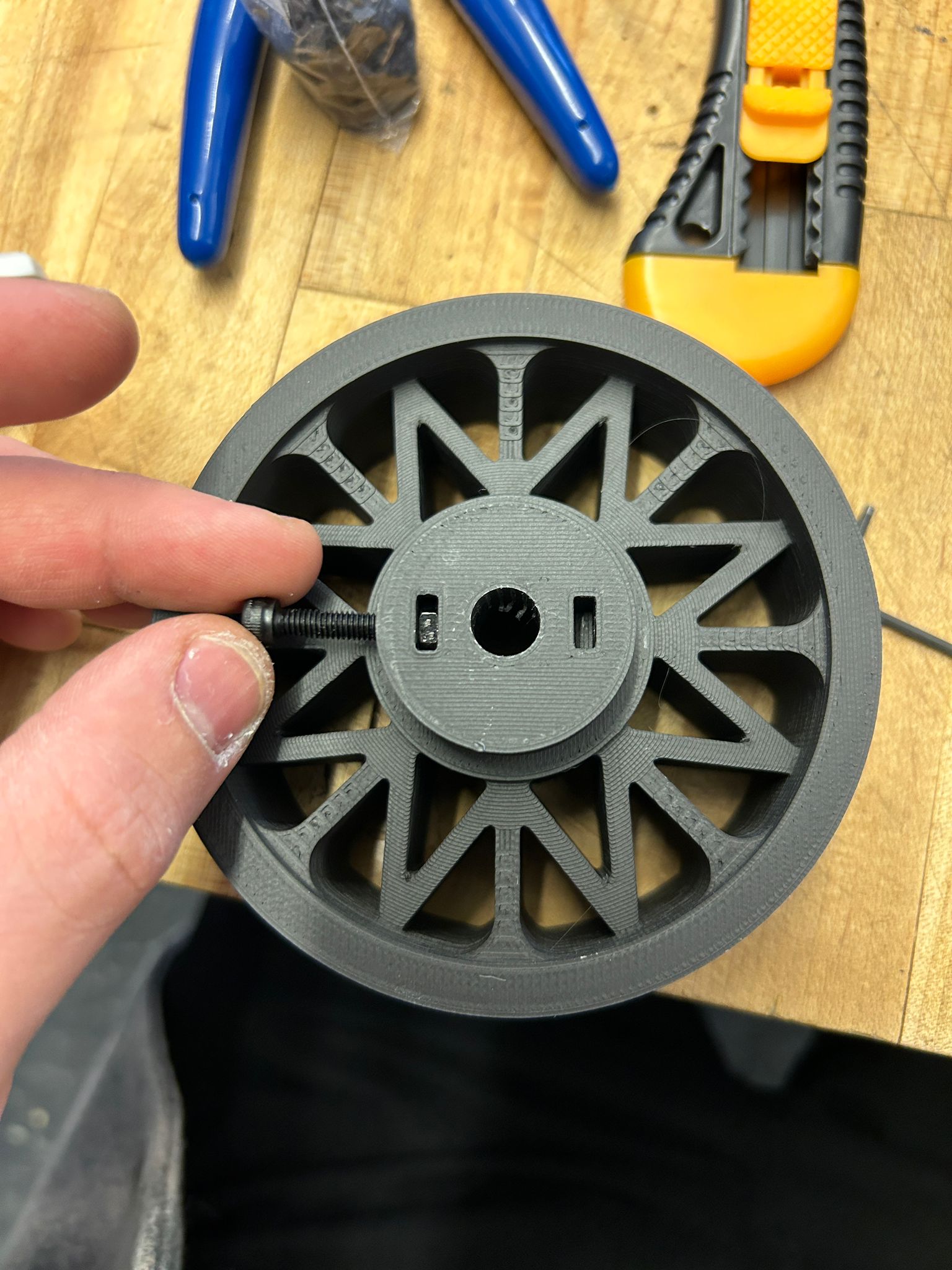
after that worked out, i wanted to try my luck in making my own omni wheel, i designed it with 12 rollers per wheel, 6 on each plate and offset by 30 degrees, so the wheel would work normally when going into one direction but the rollers would allow a perpendicular motion if force was going in another direction. in a 3 wheeled car, this would neable motion control in every direction respectively.
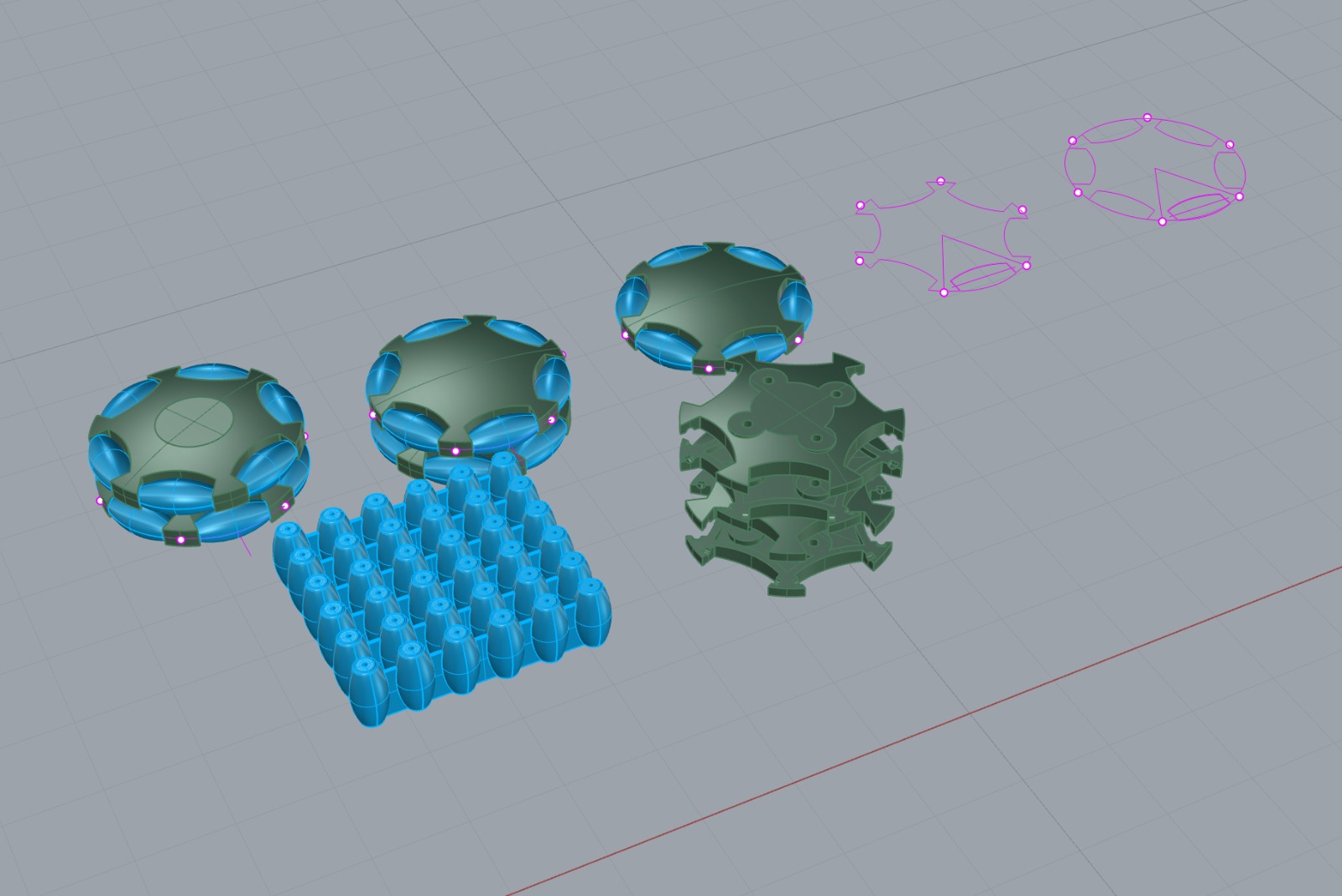
i started by printing my first verison of the omni wheels using a prusa mk3 and matte black pla
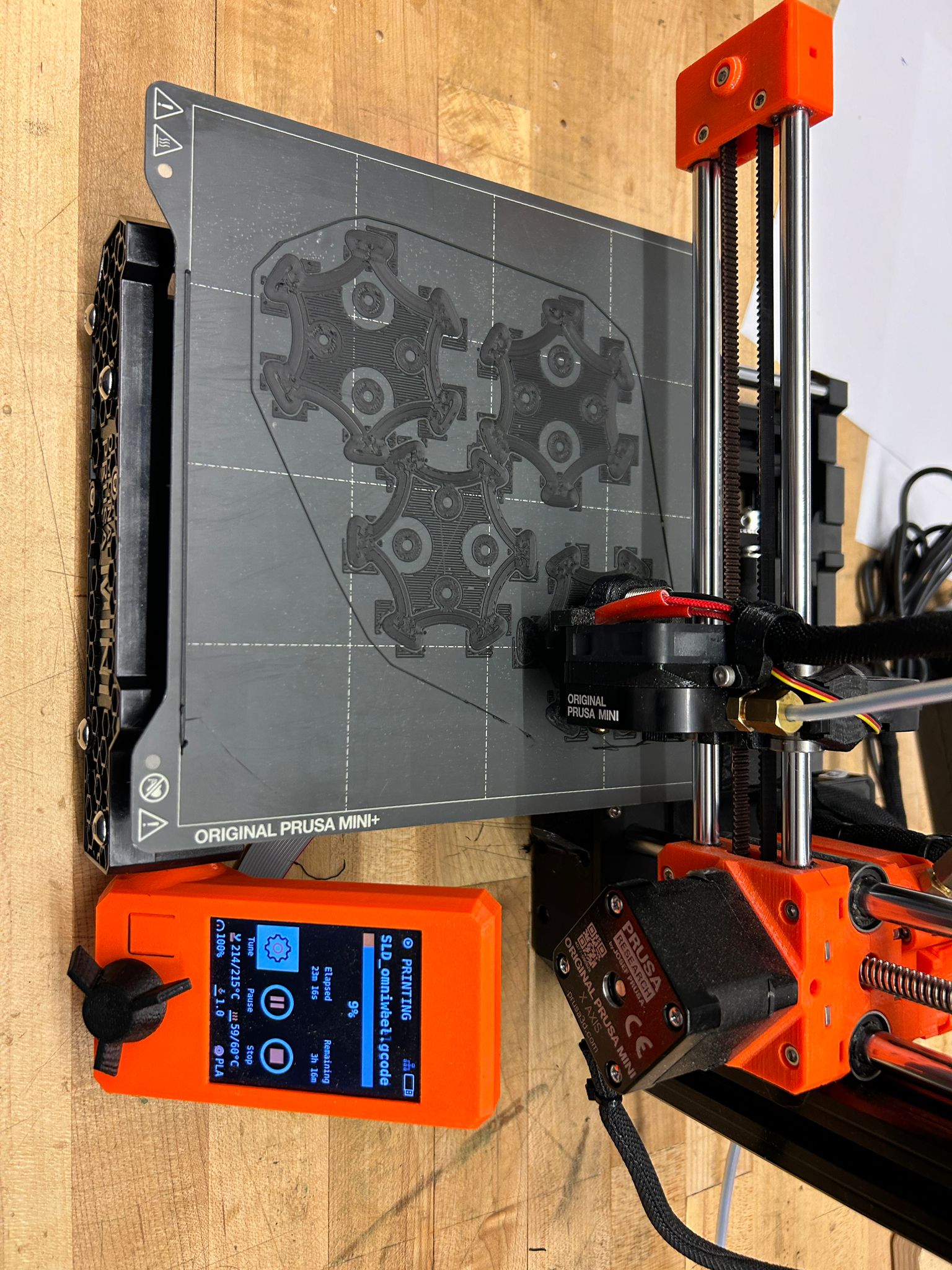
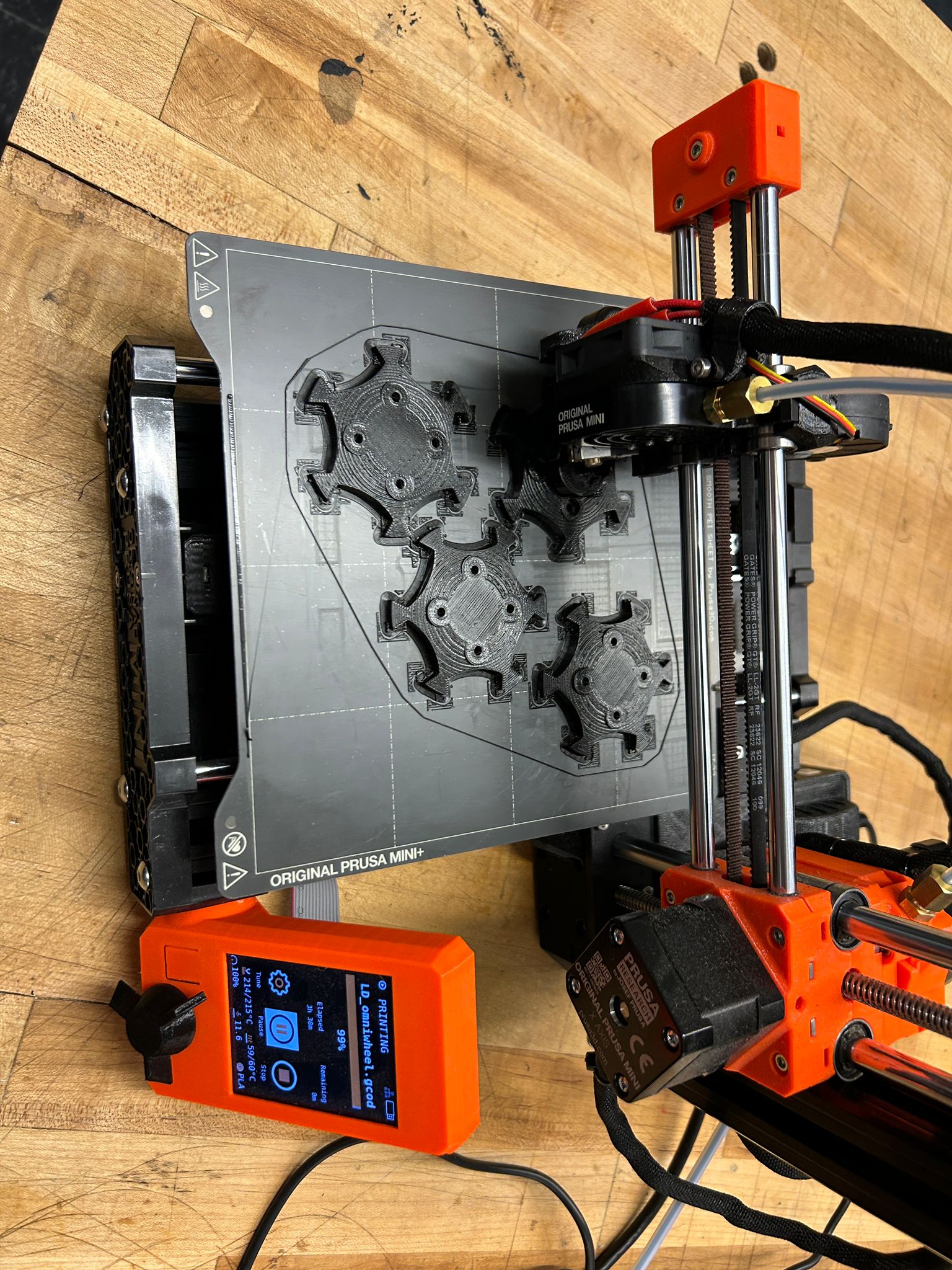
i was pleased with the result and was able to push nuts into cavities on the back of the wheel, that i would later use to screw both sides of the wheel together. i needed the wheel to be printed in 3-4 different parts (for was easier because it is the same part multiple times) because i needed to add the axels of the rollers in between each of the layers.
i made the axels by cutting thin metal rods into the neccesary lenght for the rollers.
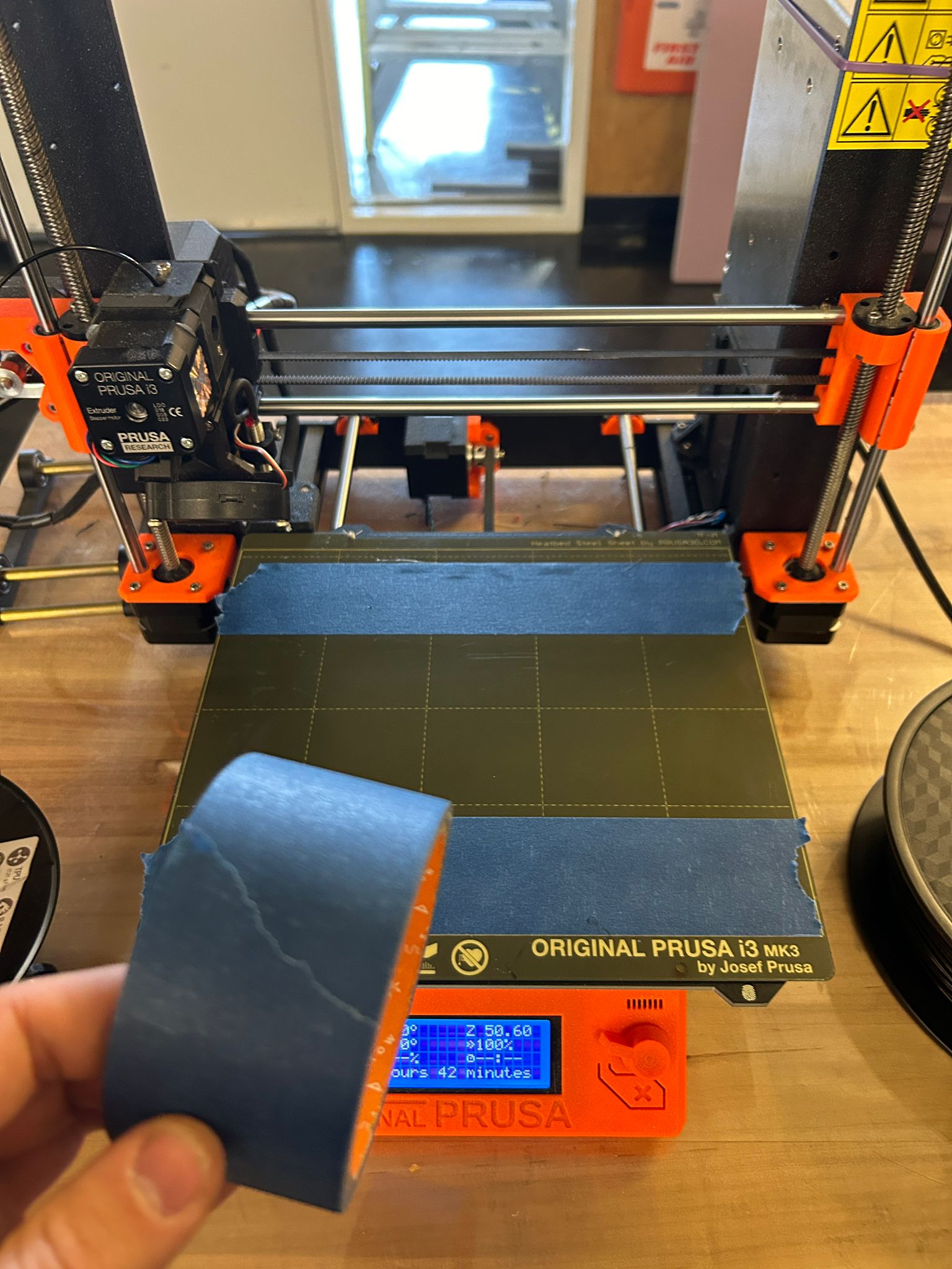
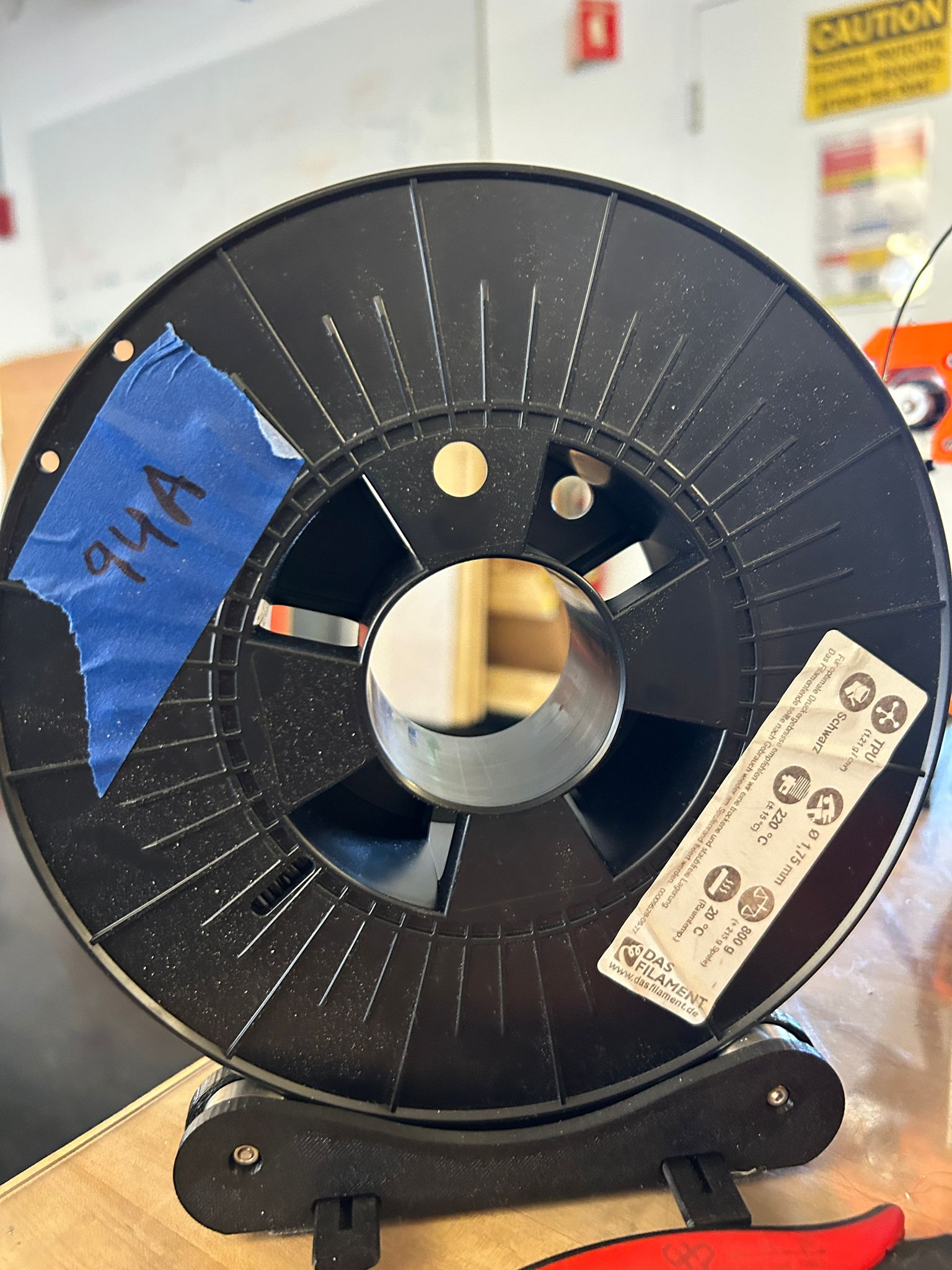
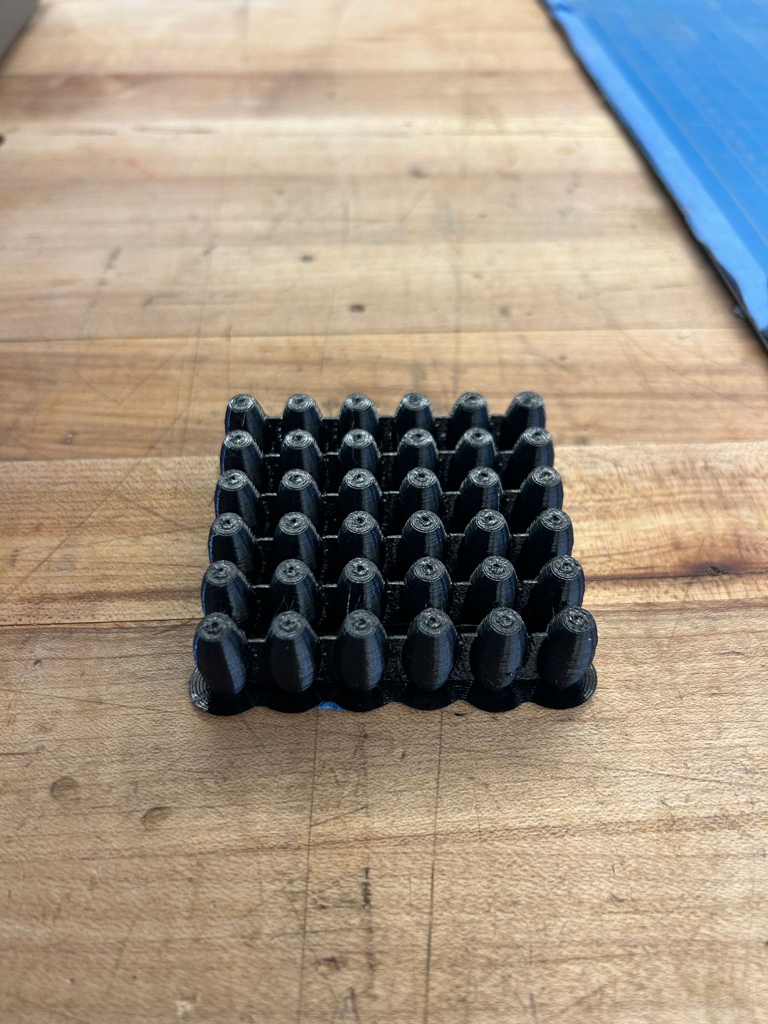
then i started loading TPU into one of the prusa MK3 printers (consult with your shop staff about specialty filament) for the rollers, so they would have a little more grip. when printing TPU it is best to put a layer of masking tape down on the print bed of the printer, since it will stick very strongly to the build plate and might not come off at all in some cases.
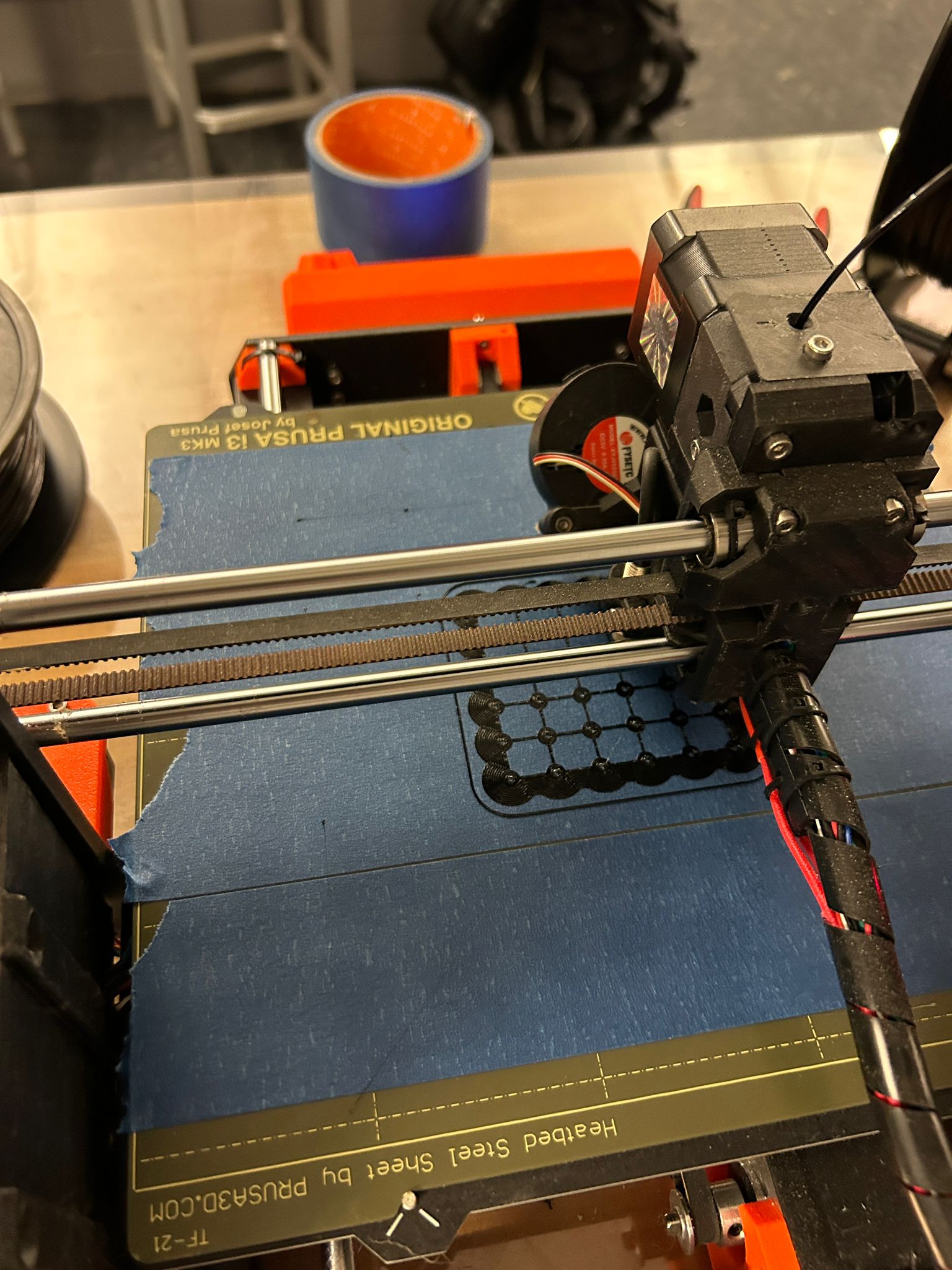
the result where a bunch of nice rollers that were connected by a very thin wall to the other rollers. the reason i decided to do this was to eliminate the risk of a roller falling over and failing the print. since this is basically one continuouse extrusion for most of the layers it helps stabilize the print job all together
the motion of the connections when compressed had a fun effect that i hope to explore more in the future for single-shape actuators or joints.
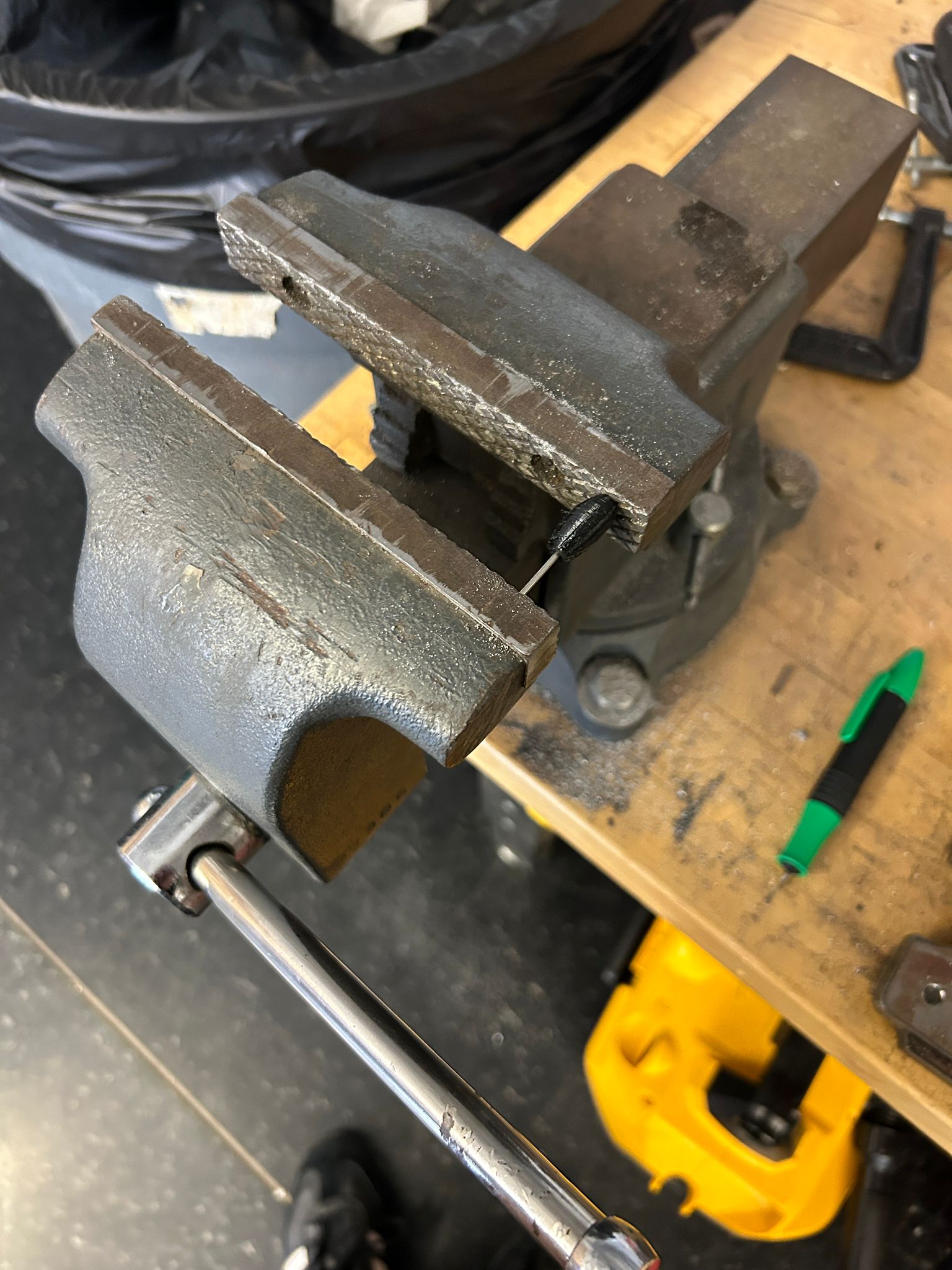
the internal hole in the TPU roller was designed to be smaller than the metal rod that i intended to use as an axel so they would hold together without the use of glue. i found that pushing the metal rod in a bit and then clamping the entire thing into a vice and closing it was the most efficient and controlled way to put the two pieces together.
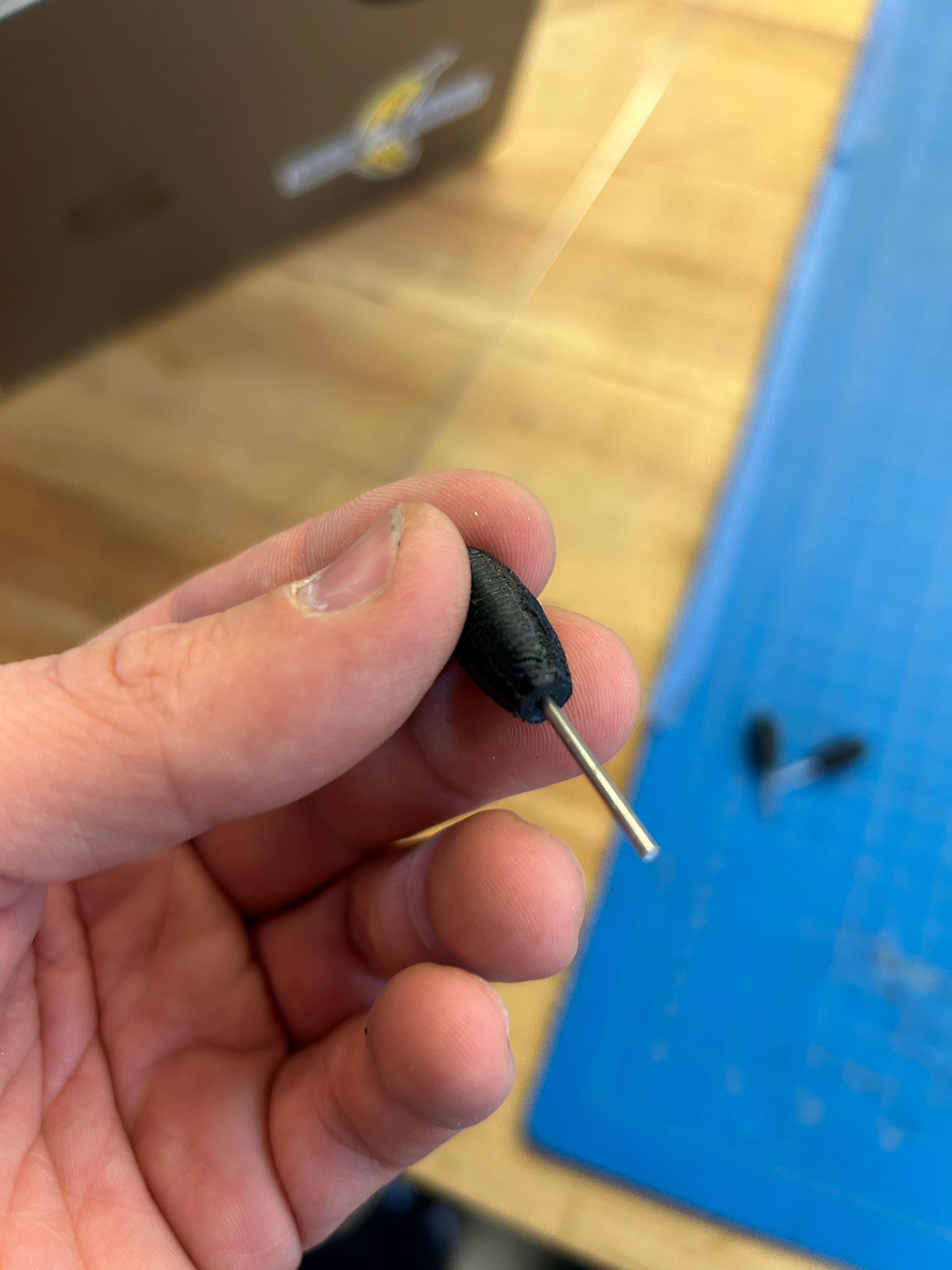
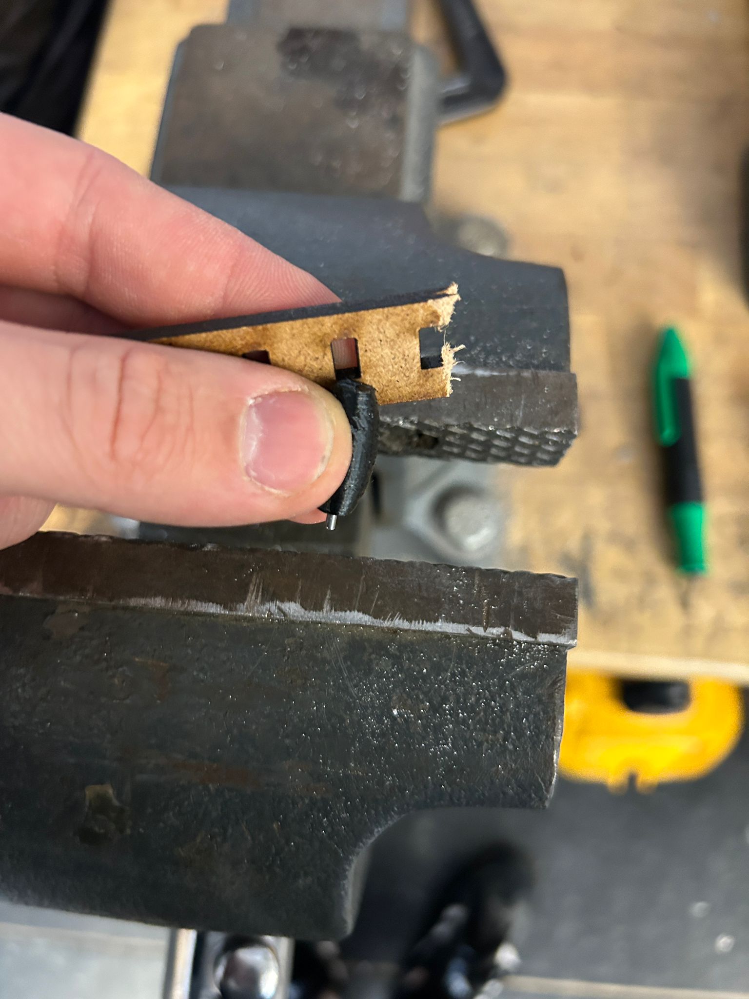
for the final part, the axel needed to be pusht beyond the roller, so i used a small piece with a hole, put it back into the vice and pushed it for another 1.5mm
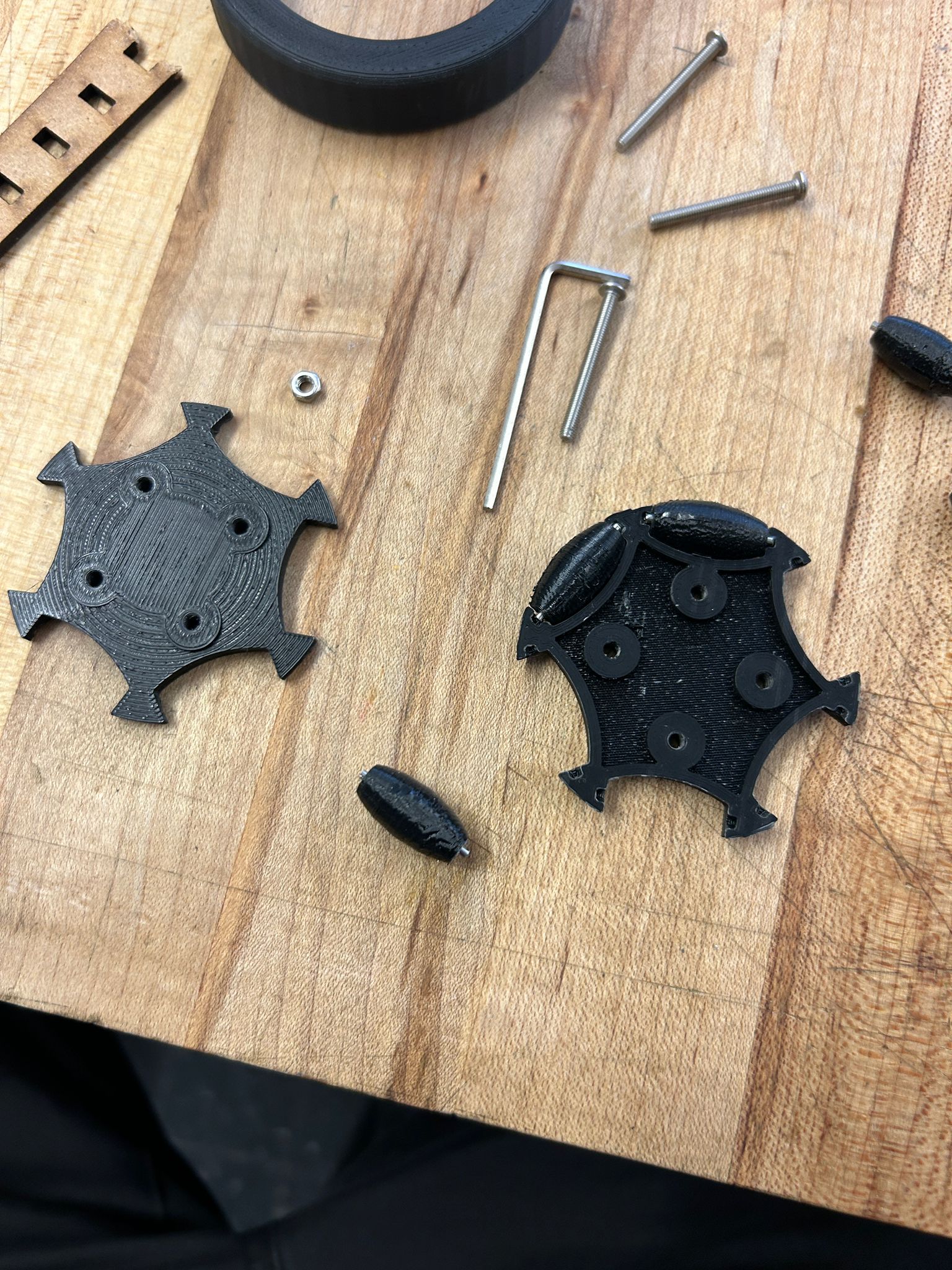
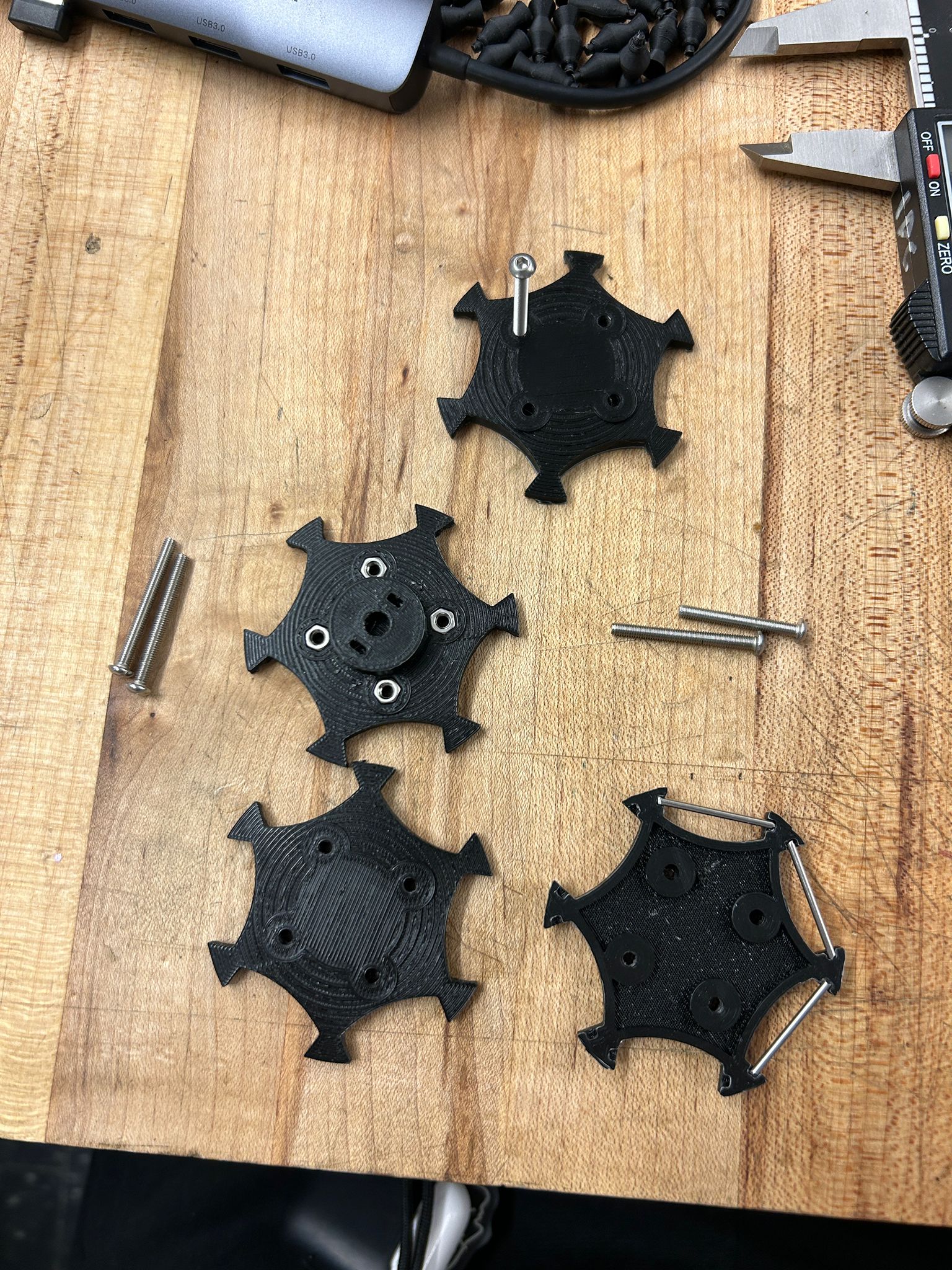
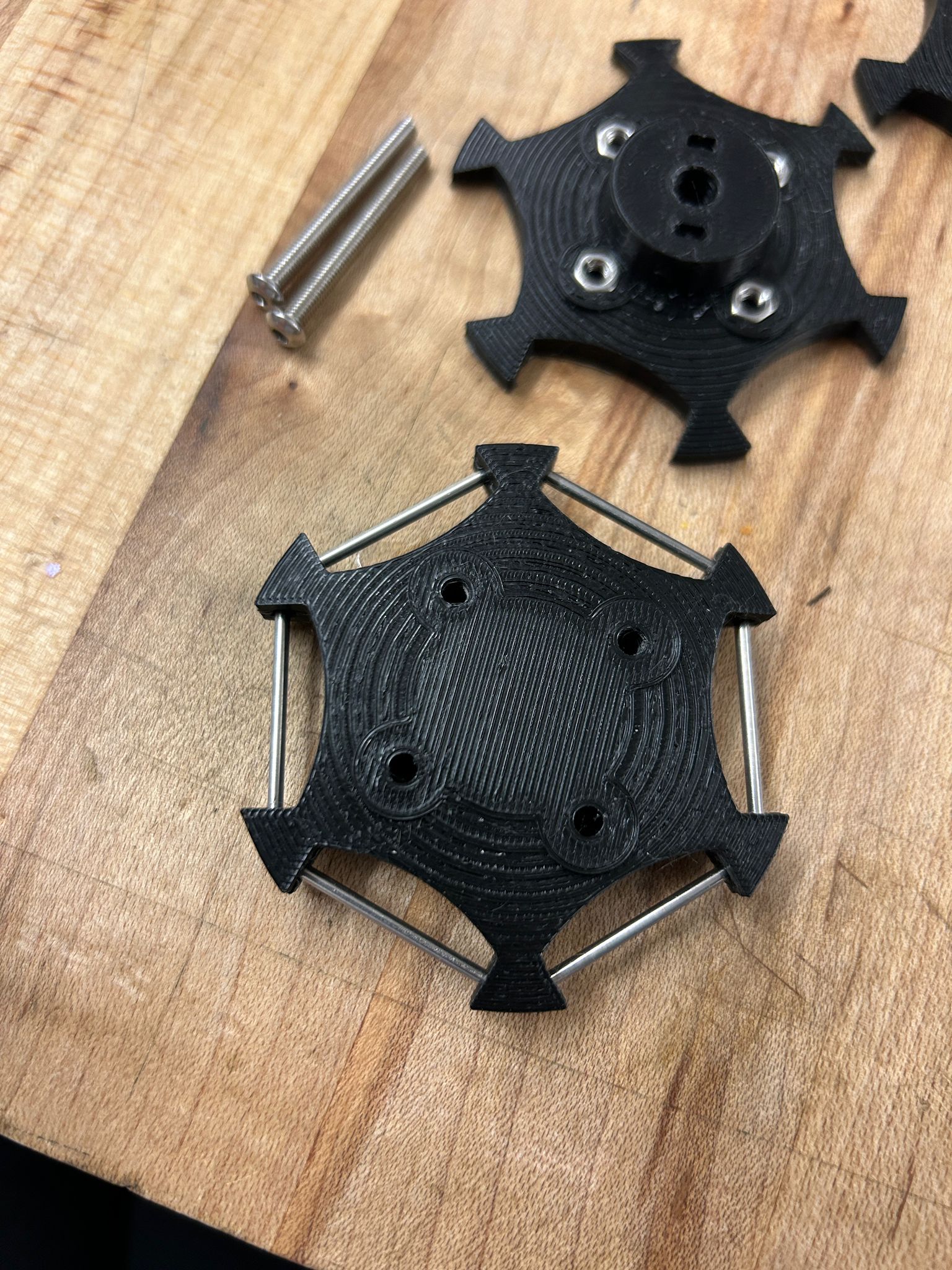
putting the pieces together i realized that they wouldn't spin as freely as i hoped, so i redesigned them so the PLA shell would get a small metal washer,
into which i would place the axel to reduce friction of the rollers. since i spent so much time on these wheels i decided to work on another part of my project for a moment.
in the end i decided to go with a different motor setup to save weight, but if anyone is interested in experimenting with these omni-wheel shapes (they are not perfect at all) see
the .stl files here:
PLA Wheel
TPU Wheel
i modeled the exact shape of the upper lip of the spray can to create a 2/3 circular clamp that would be able to latch on. knowing a few of the tolerances of the prusa printers at this point the first latch i designed snapped perfectly into place.
after this i ended up designing the first of many versions of a potential spray can actuator. this version used a very small servo that would turn a small gear, which in turn would move a linear gear up, which would rotate around a column, and like a lever, would push down on the spray can cap.
a few hours later i had a print ready but it turned out to be flawed in many ways. on one side the print with just 15% infill was done fast, but too weak to sustain the forces of the actuation, and would ultimately rip the screws out through the print, but on the other side, i also realized that the servo was just too weak to push this version of the actuator. the force needed to push a spray cap down is much higher than expected.
a friend found a drone, knew about my project and donated it to me. i originally wanted to strip it for parts, but everything was there, controllers, fully functional battery, dron and camera as well as charger... after flying it around my apartment i decided not to take it apart after all...
while the mechanism wasn't fully working, i wanted to see if the spray can that i was using (this type is called a "skinny cap" for its small opening) would actually clear the opening from the bearring I wanted to use (more about that below), so i taped it off and tried spraying manually through.
seeing this it became clear that a "skinny cap" would not be enough, i could chose a larger bearring defining the size of the opening or i would find another cap. I actually found a smaller cap later on, which is known as a "ultra-skinny cap" mainly used for detailed outlines or spray distances where one cannot get close enough to the wall. They use normally a skinny cap and have an additional acrylic tube attached (about 0.5in long) that allows for that.
while the servo did not work at this time, i tried manually pushing the lever up, which revealed that the 15% infill i used to print this piece, was not enought to sustain the forces for actuation...
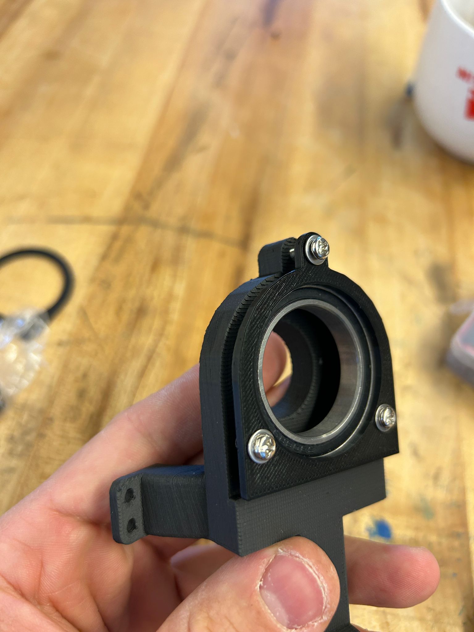
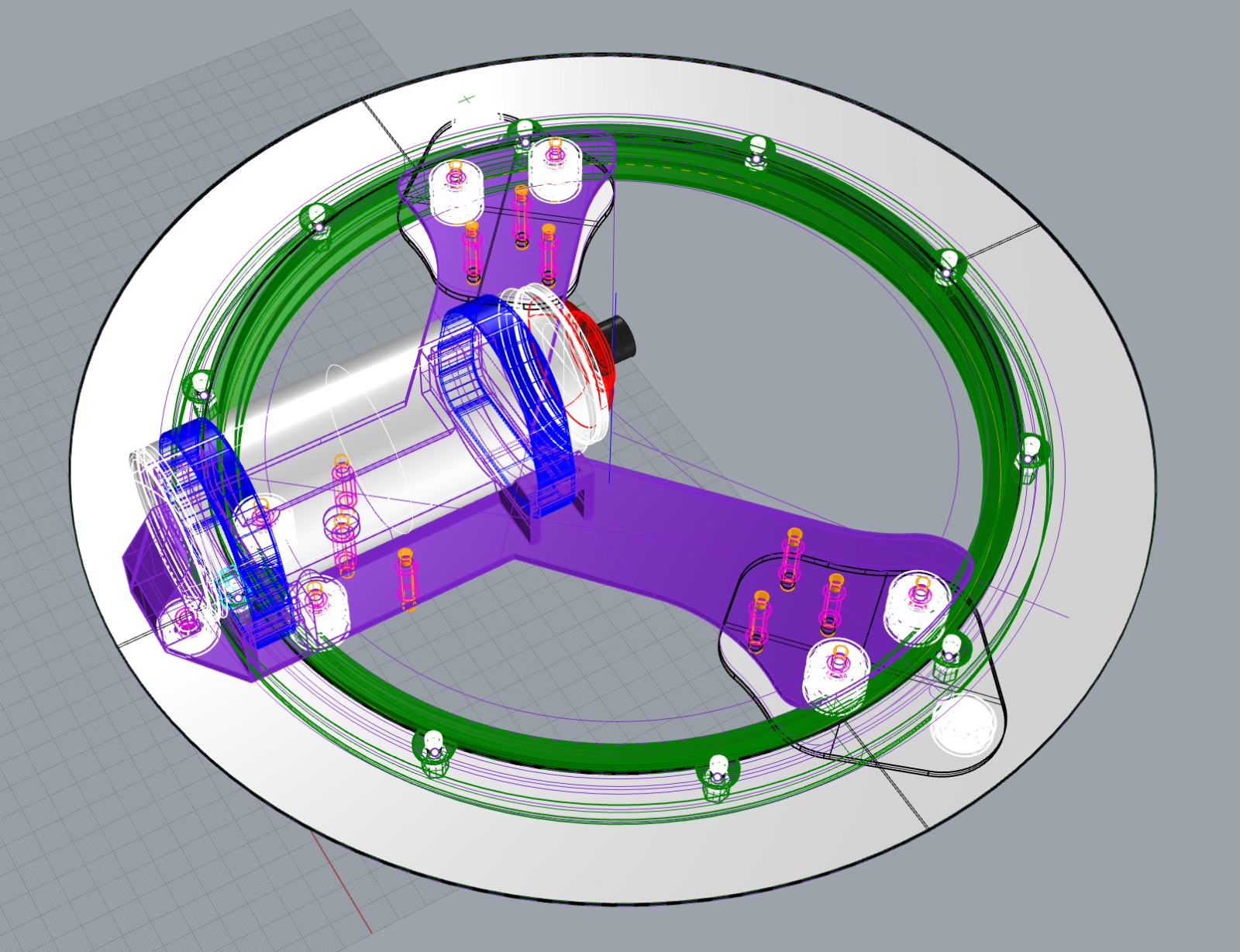
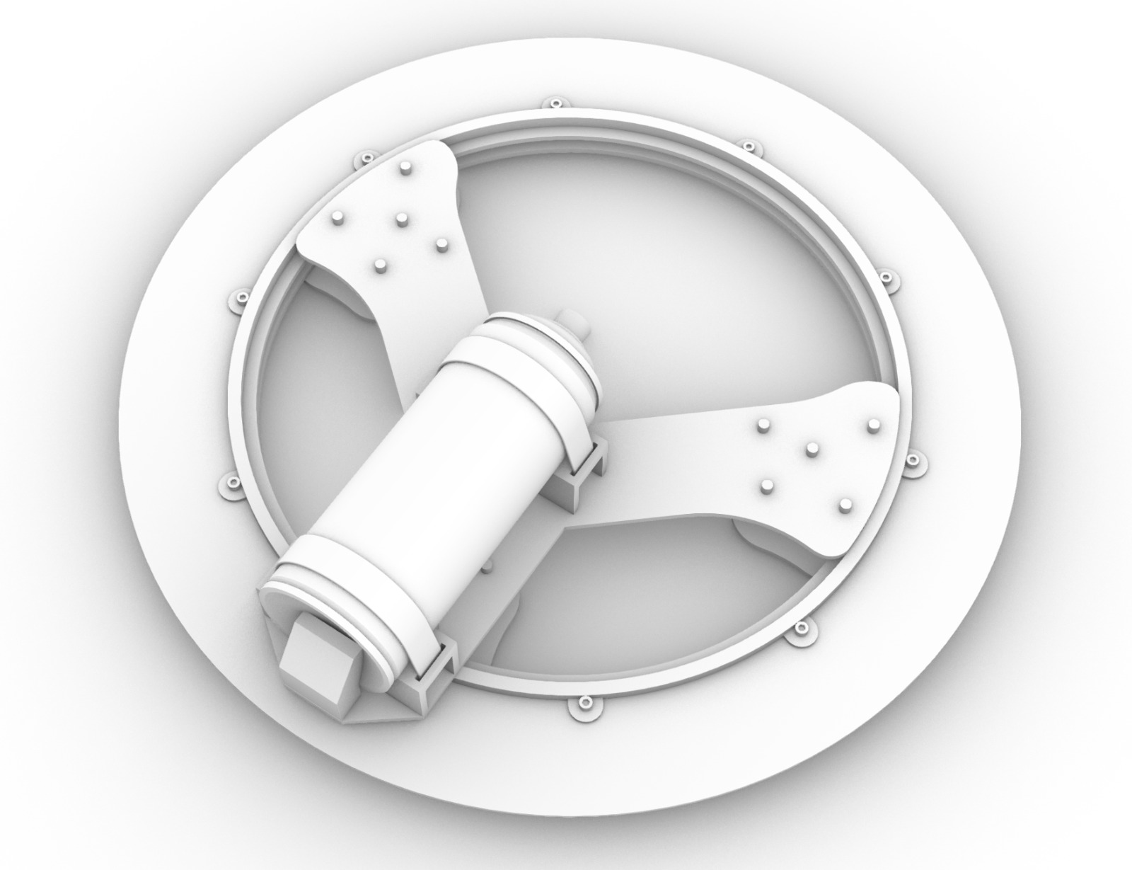
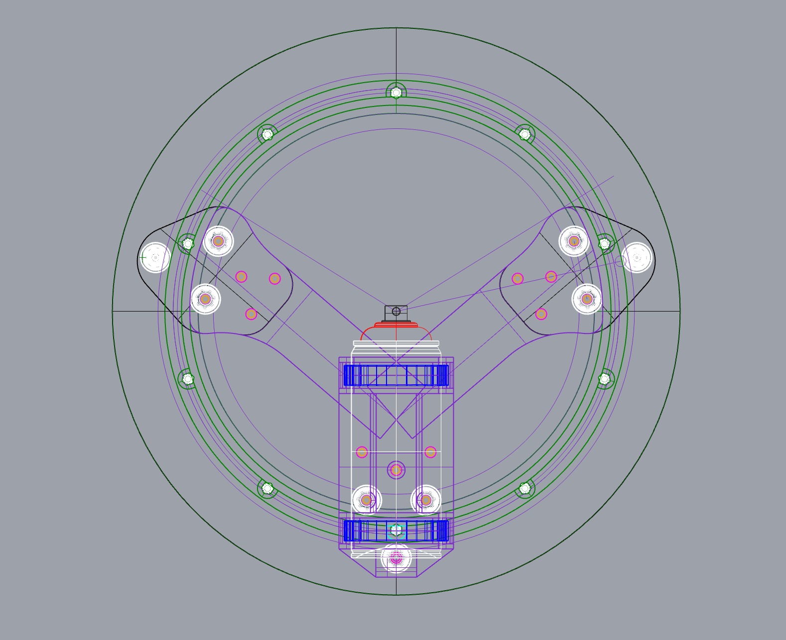
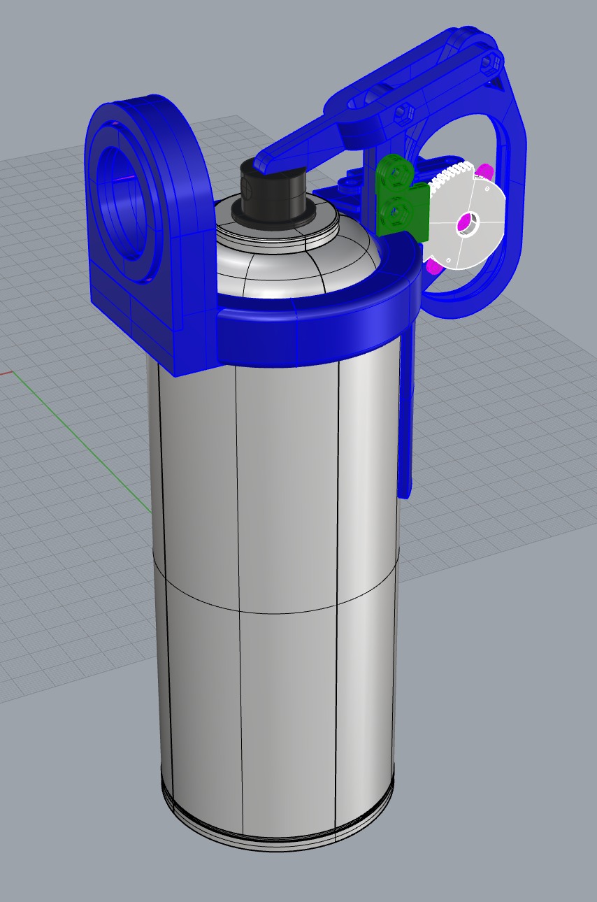
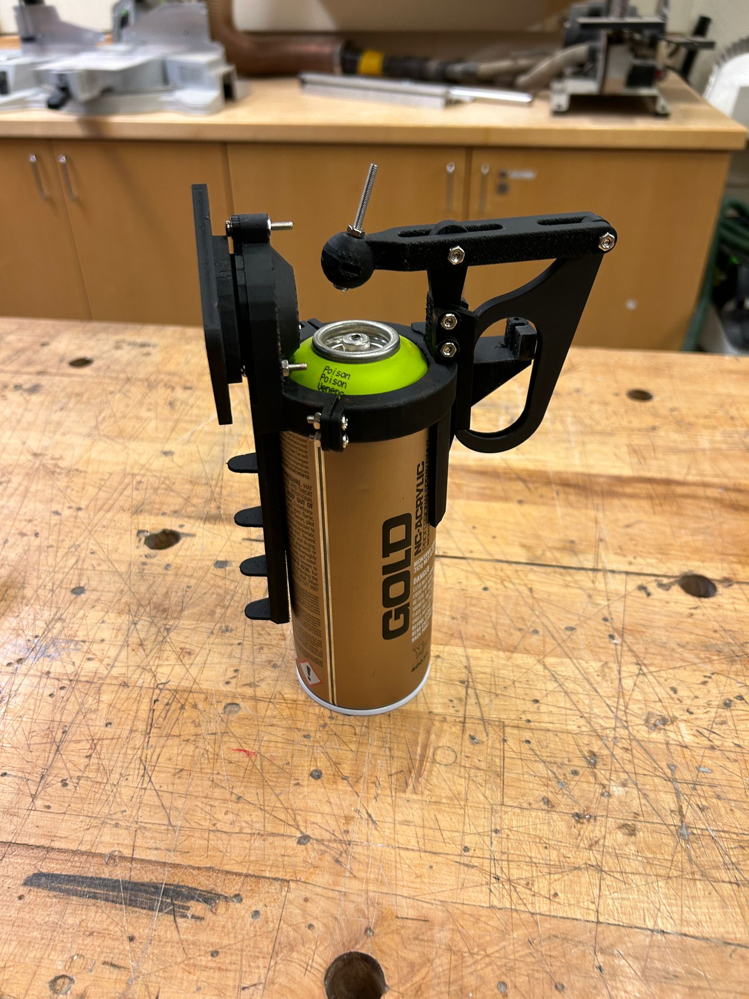
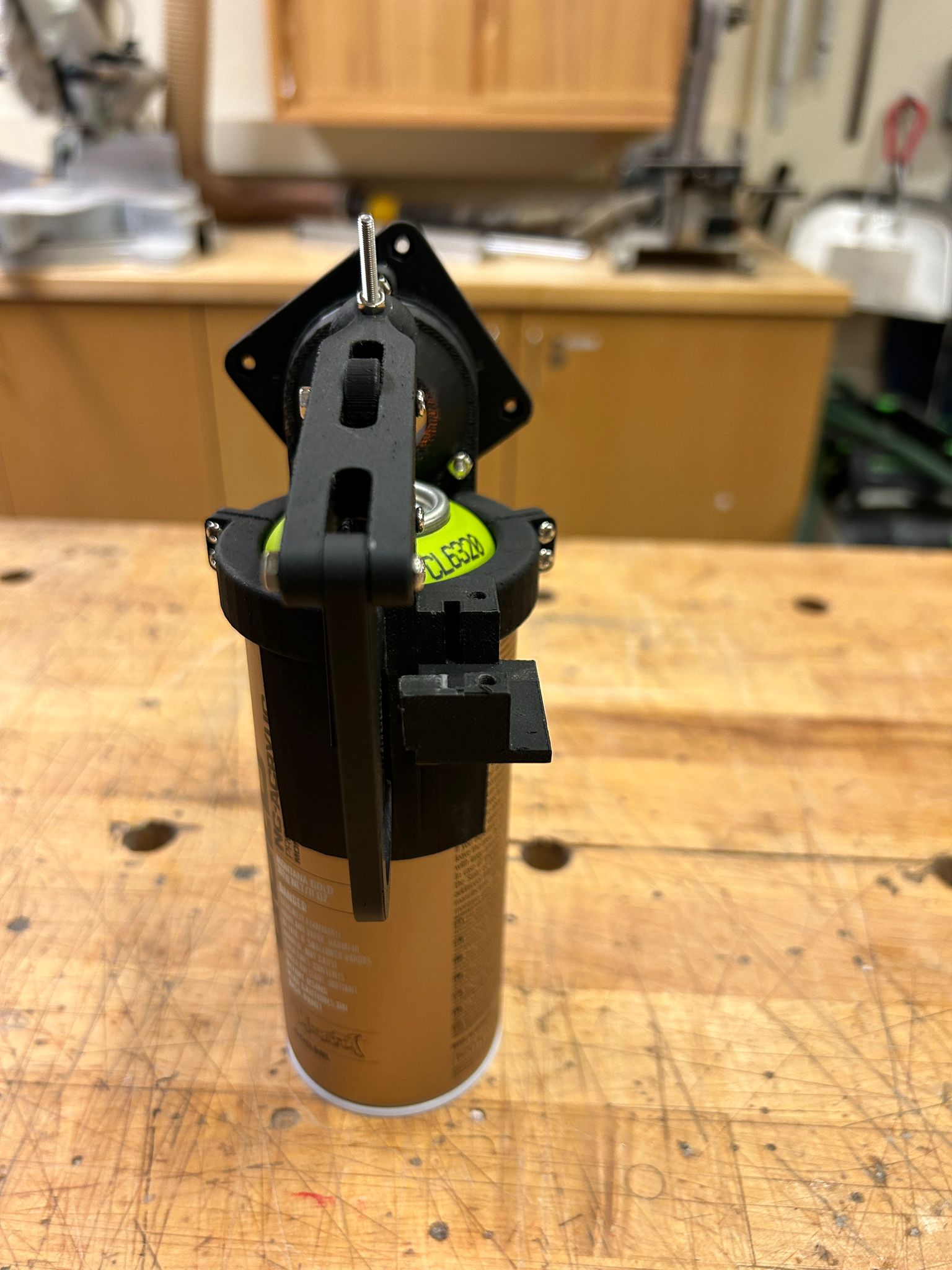
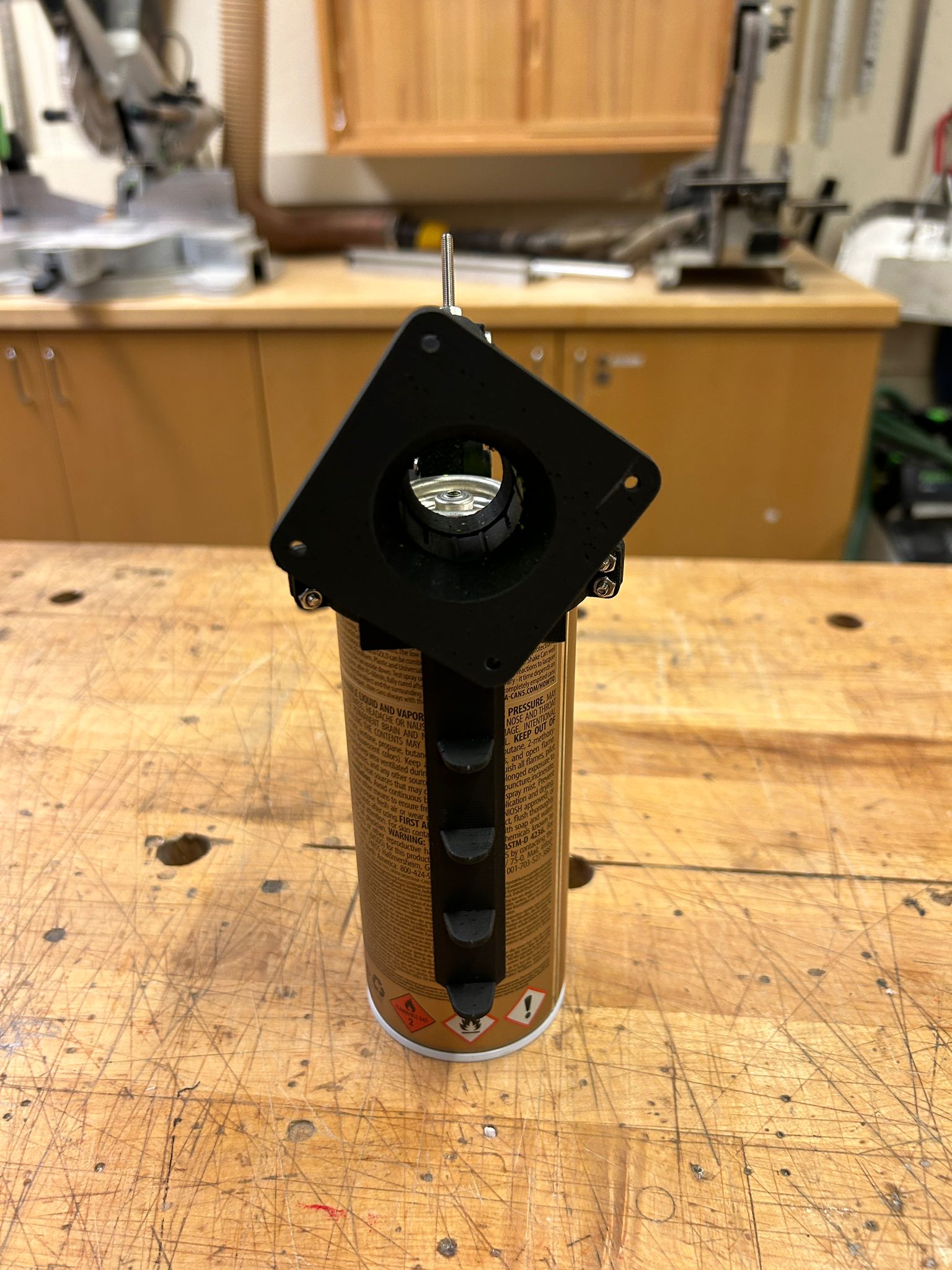
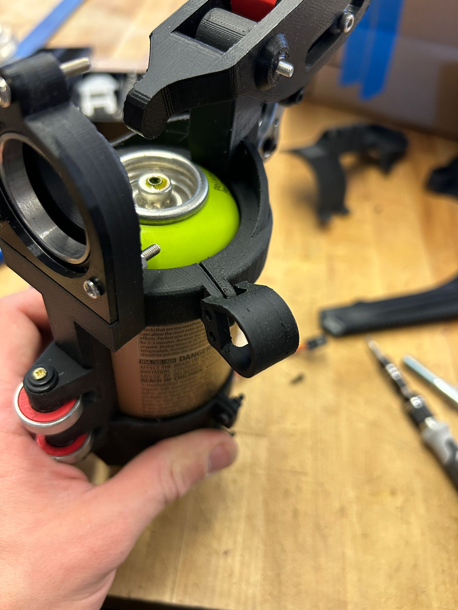
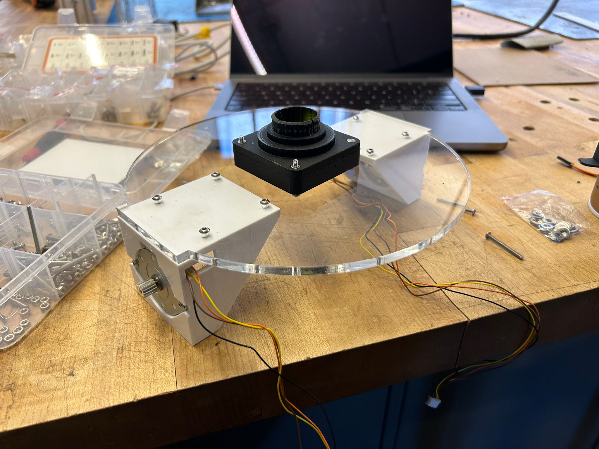
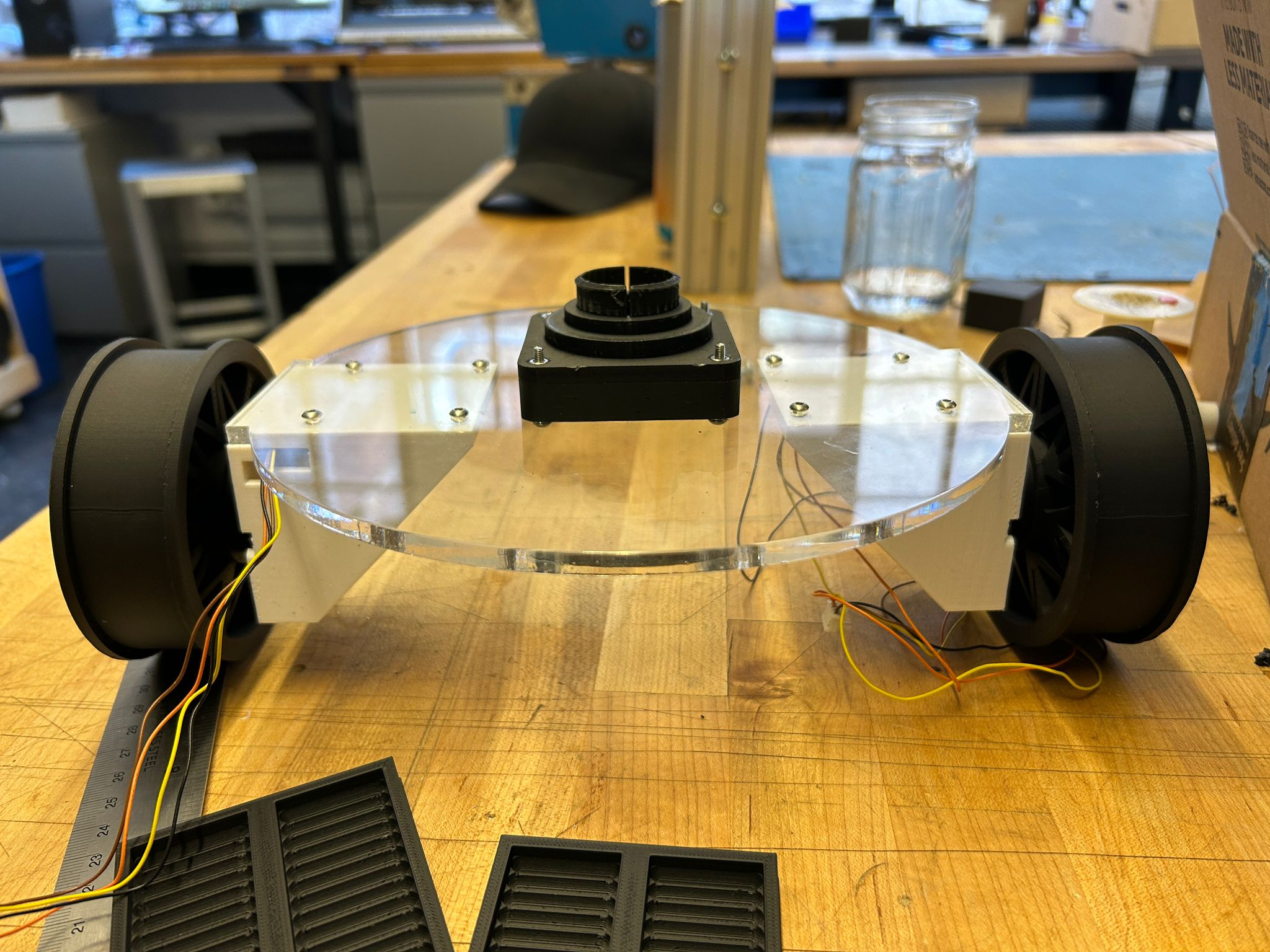
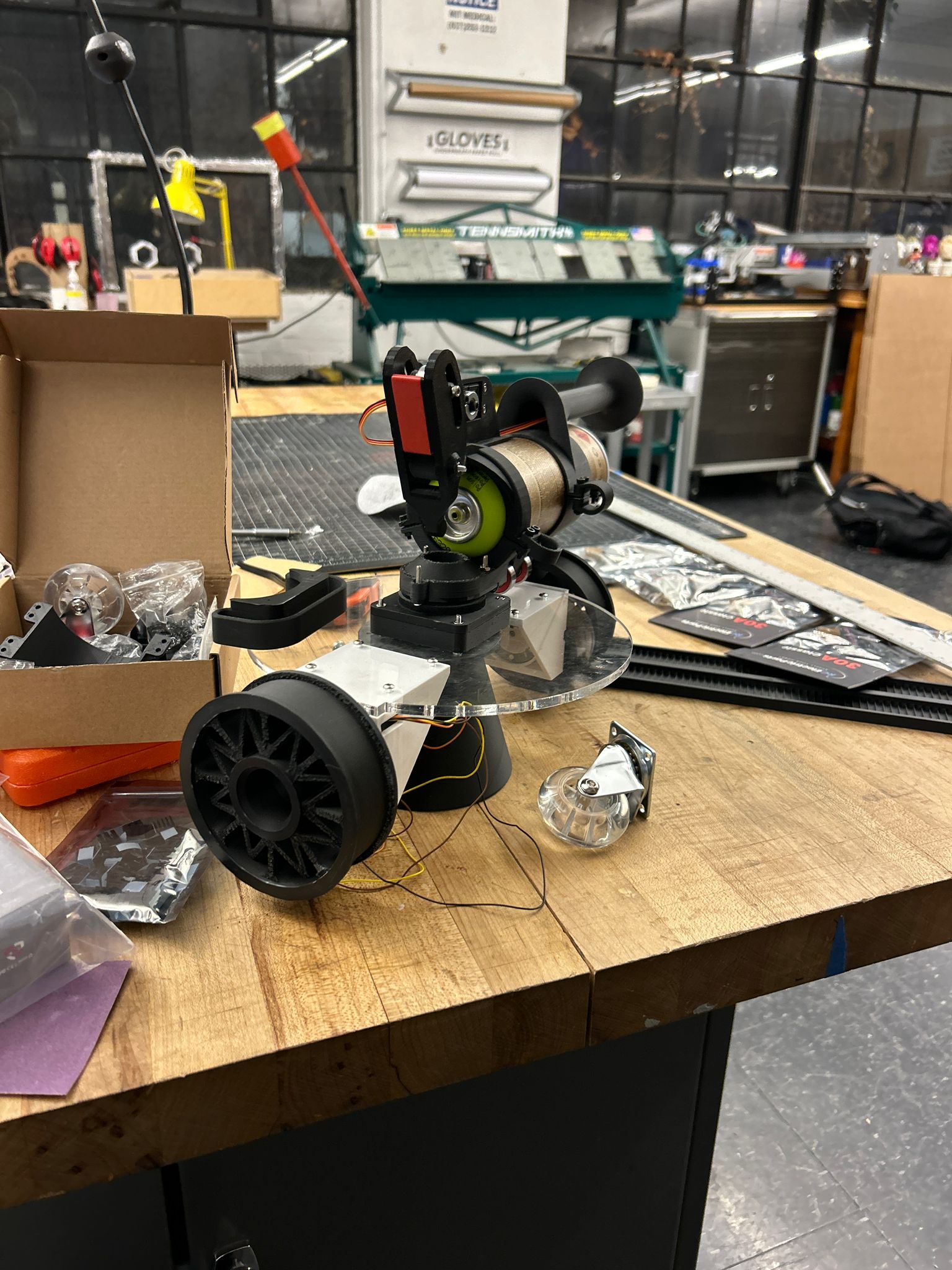
since i wanted my graffiti car/dron should be staying on a wall, it is crucial that the spray can stays as perpendicular to the ground as possible at all times. i decided to think around a system that would allow the wheel with chassis to move freely, while the spraycan can rotate itself towards the ground. I could automate this using another motor, but the easier way to achieve it is to have the spraycan mounted exactly centered to my vehicle (since i intended to use a 3 or 2 wheeled drive), mounted with a large bearring that would be able to be cleared by the spraypaint.
so i was tinkering around a solution that would allow me to press-fit the bearring into the spraycan clip, runnin on the outer rim of the bearring, while the inside ring of the bearring would attach with a clip to the vehicle itself.
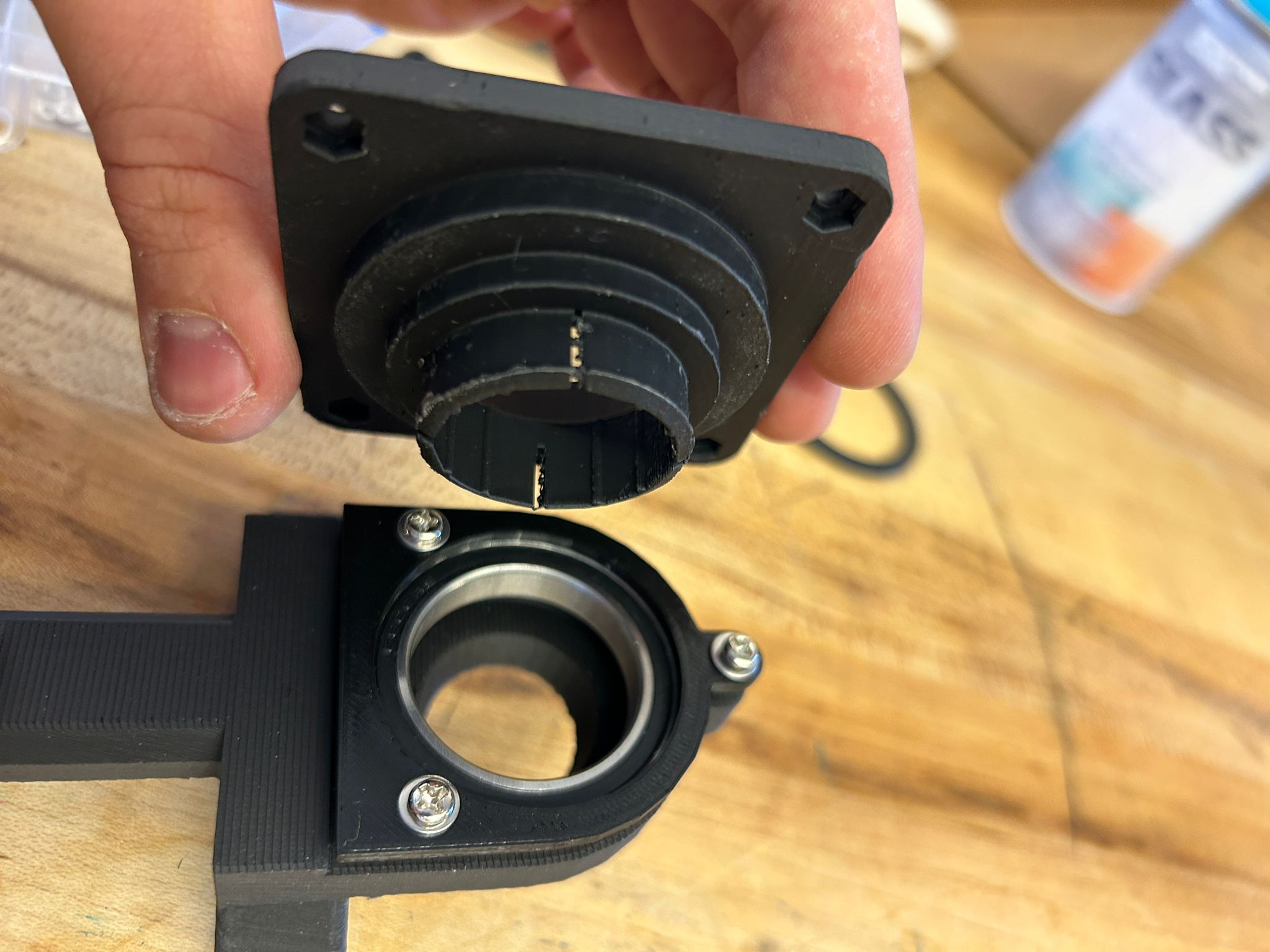
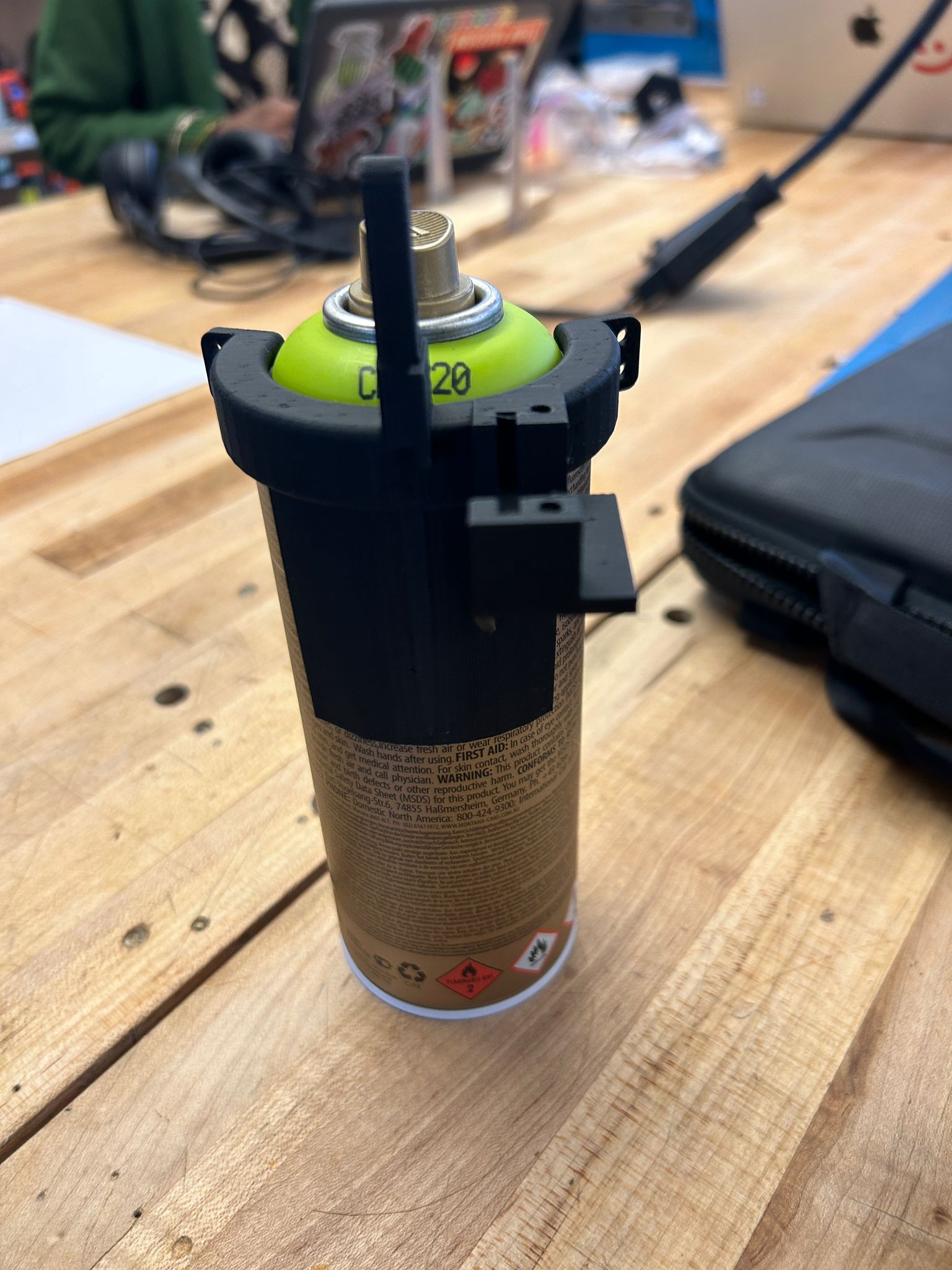
it took a couple of iterations of this clip before the PLA was thin enough not to obstruct the spray paint itself, while being strong enough to not snap off. rotating the print for this part so the lamination of the individual layers of the 3d print do not run top to bottom but at a 45 degree angle ensured that the force direction on this part is not the same as the orientation of the horizontal layers of the print.
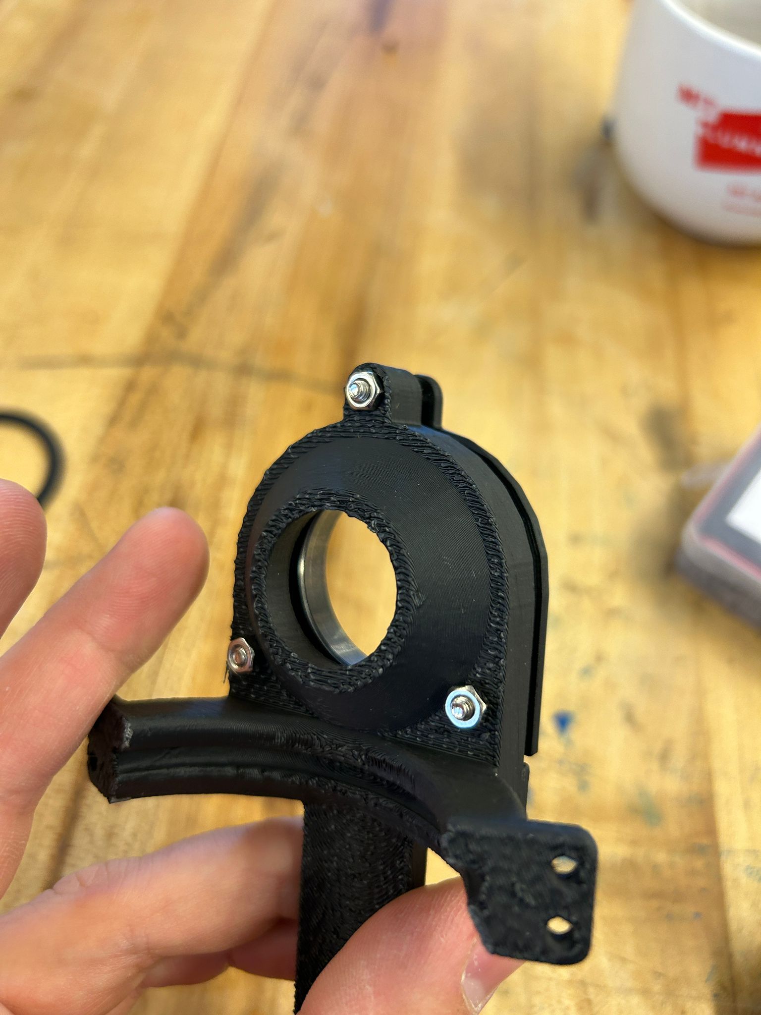
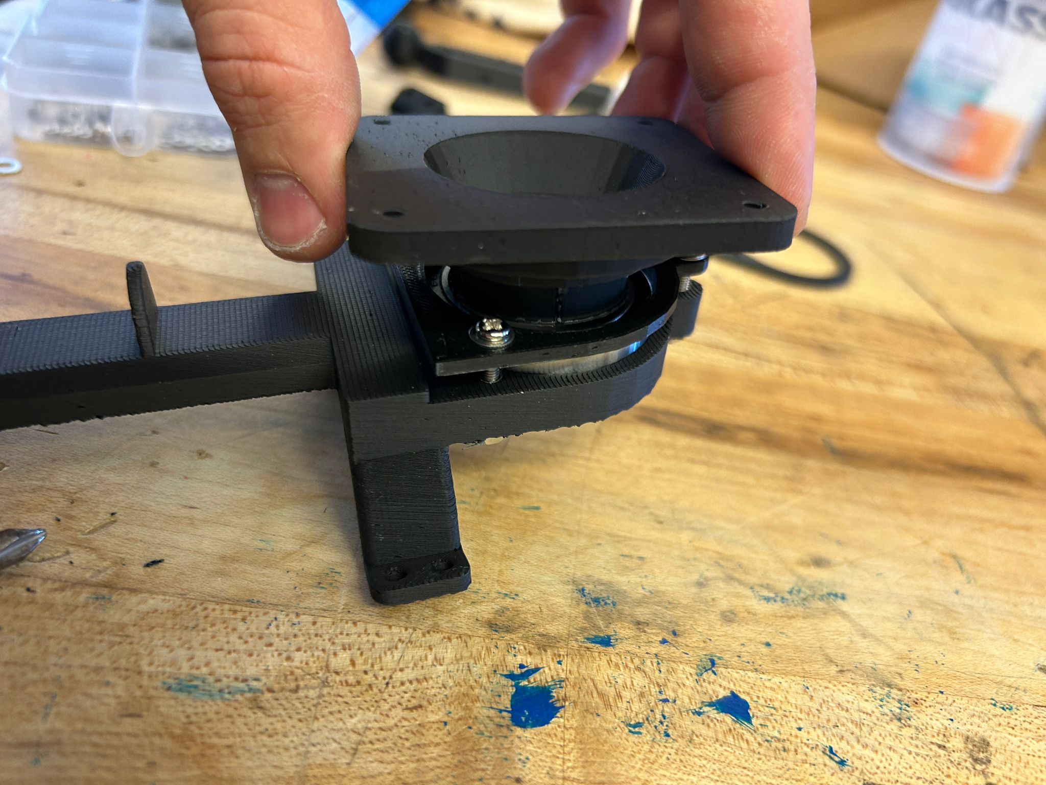
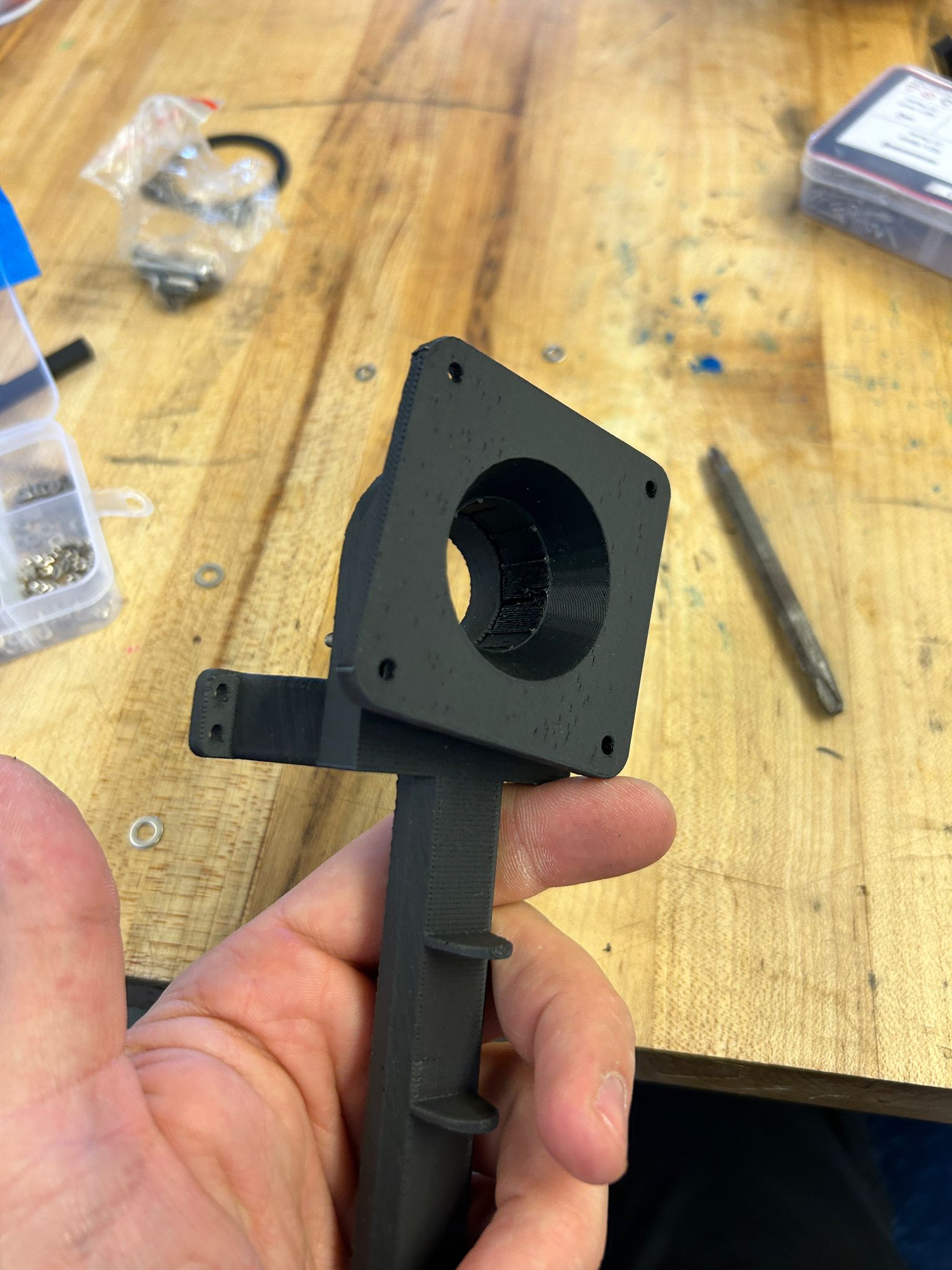
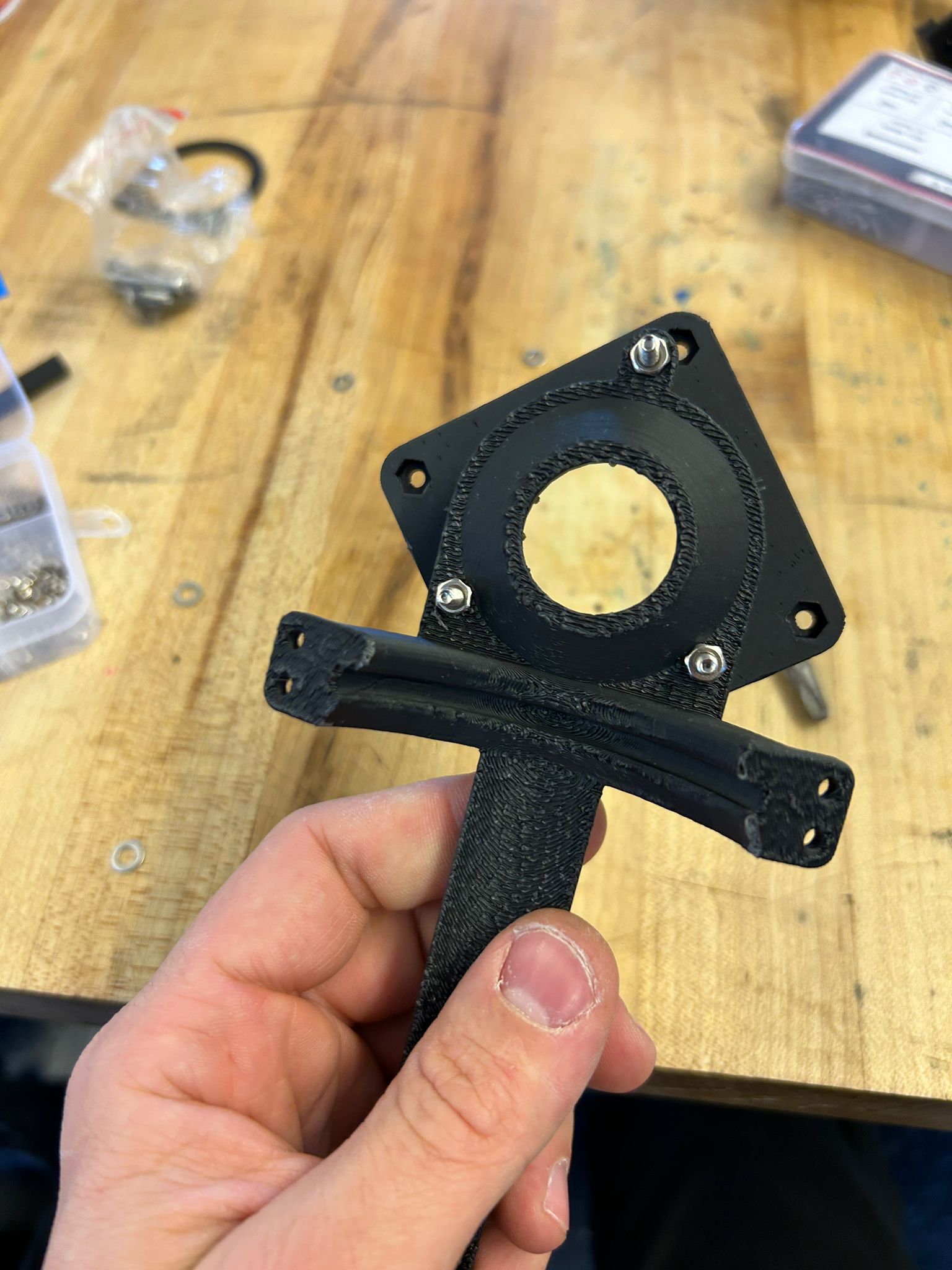
after screwing the mounting plate on, to ensure the press-fit bearing would not come lose, and clipping in the mounting plate for the vehicle, i was surprised how stable, yet movable the entire construction still was!
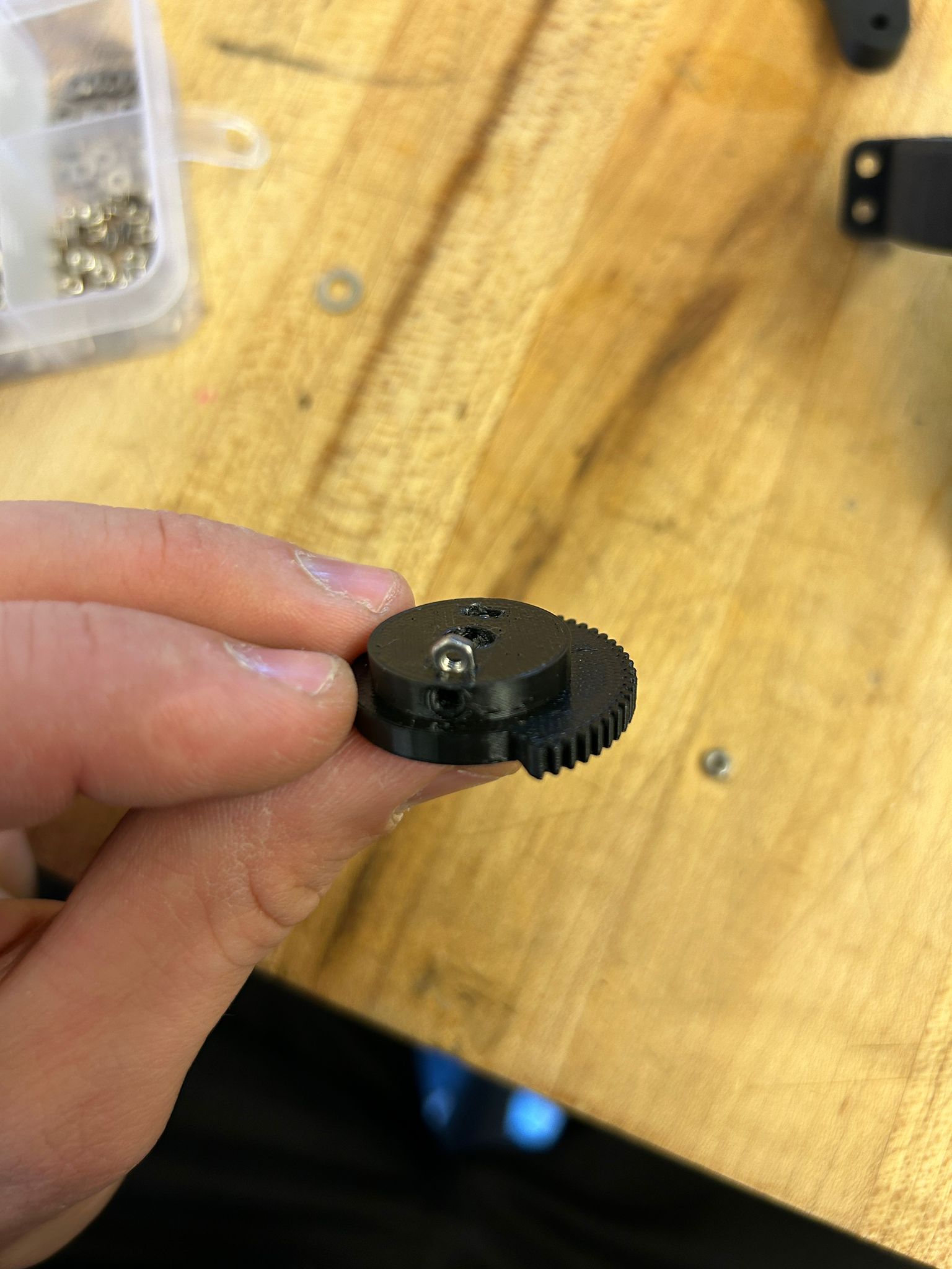
next was the actual actuation mechanism. originally i overthought the process, and wanted to attach a gear to the servo motor, that would push the lever to actuate the spray can. here i added a nut into a hole on the back of the gear that would allow me to insert and tighten a set-screw to mount it to the servo motor.
putting it all together, i had version two of the actuator, printed with 100% rectangular infill using the same matte black PLA on the prusa MK3 printers, including an actuation point with adjustable set-screw (in case i calculated any of the distances incorrectly), and i had high hopes. the meachanism worked in theory as you can see in the video below, and i has the correct range of motion, as you can see in the second video below...but the servo motor was just too weak...
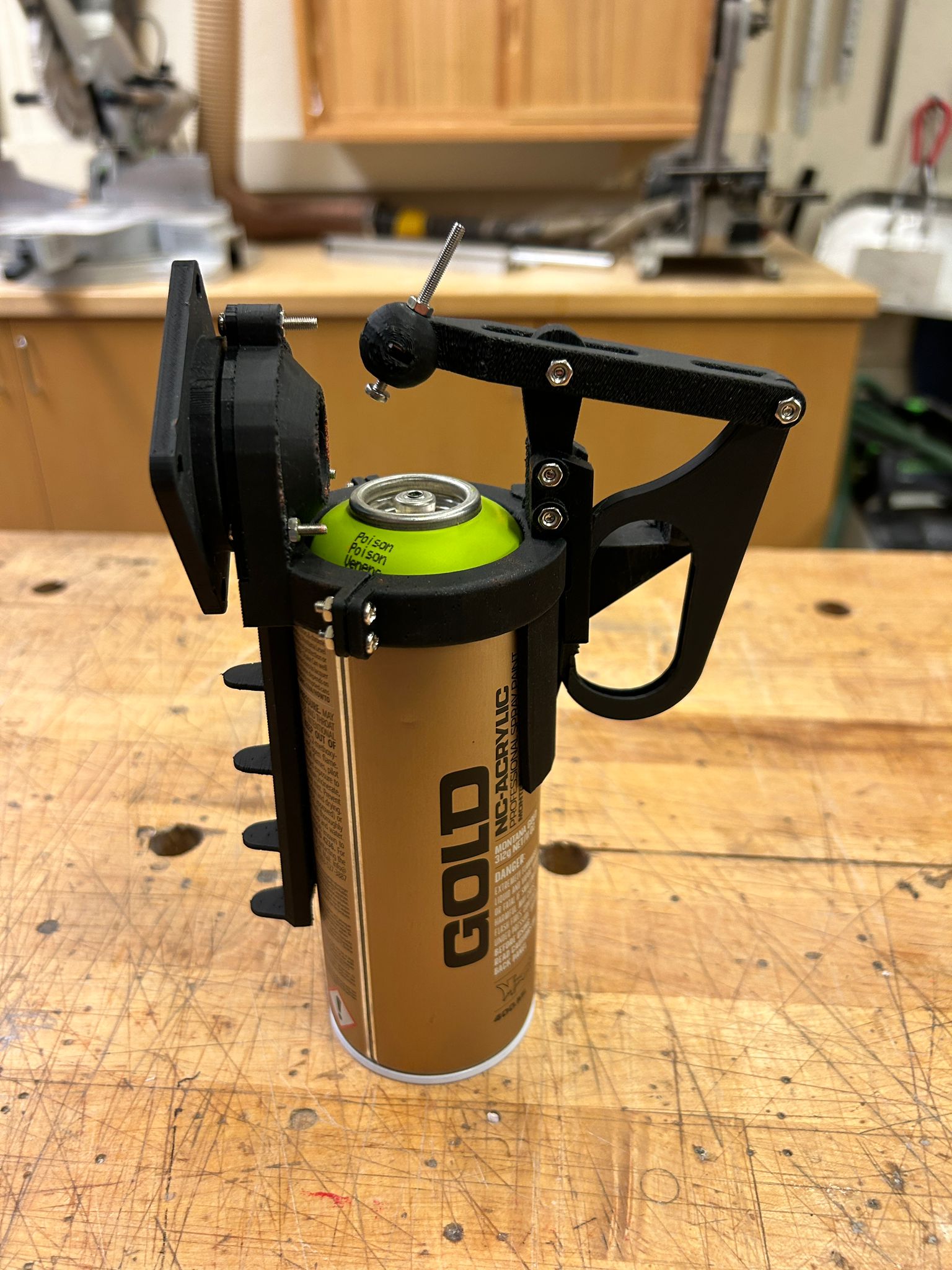
so i went back into rhino, got another larger servo motor, re-designed the mechanism, this time with a direct translation of the rotation of the servo to the lever, without any gears, and made all the components a lot heftierm and printed them again with 100% infill...
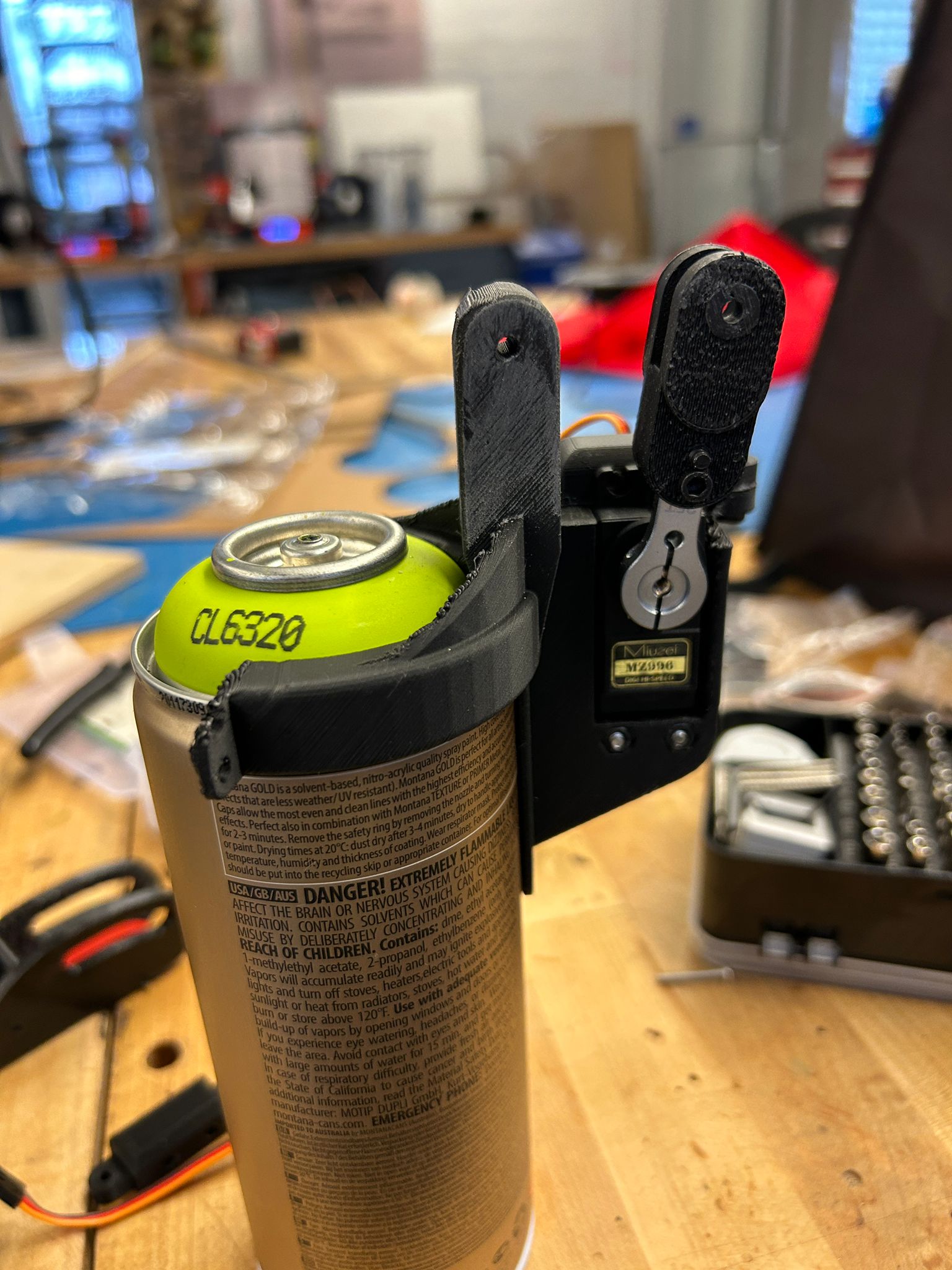
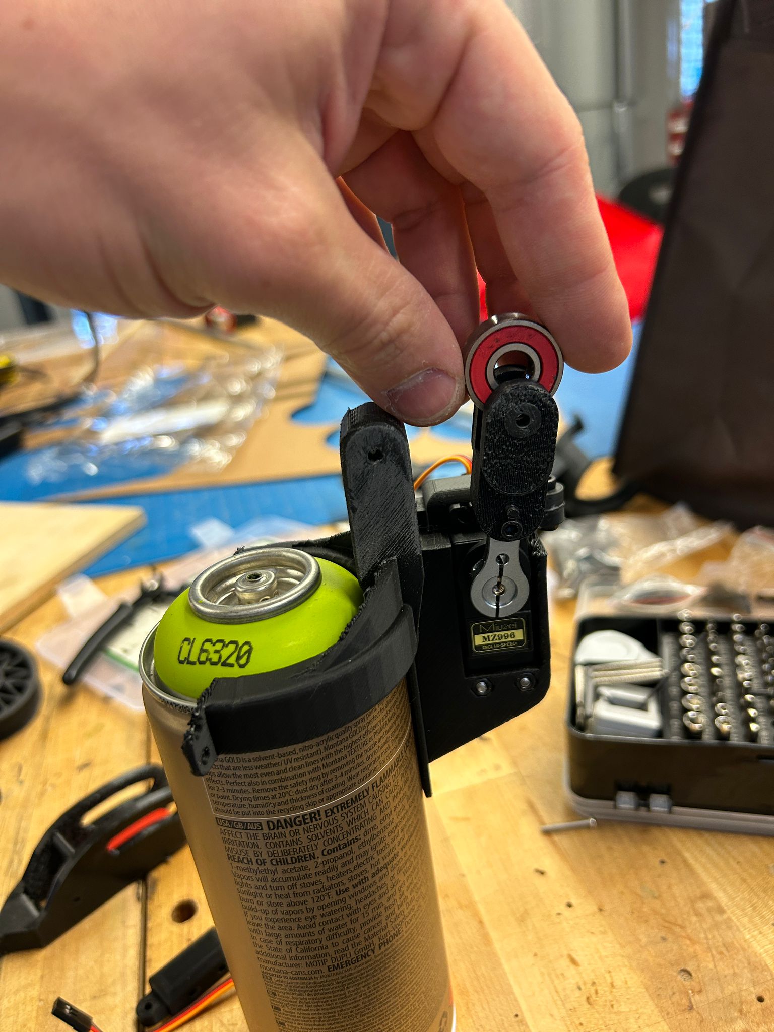
the arm of the servo motor (out of aluminum) would ensure a stable and solid connection to the servo, and I was able to print a 2 part arm to it, that would be able to hold a bearring (standard size used for skateboards and inline skates)
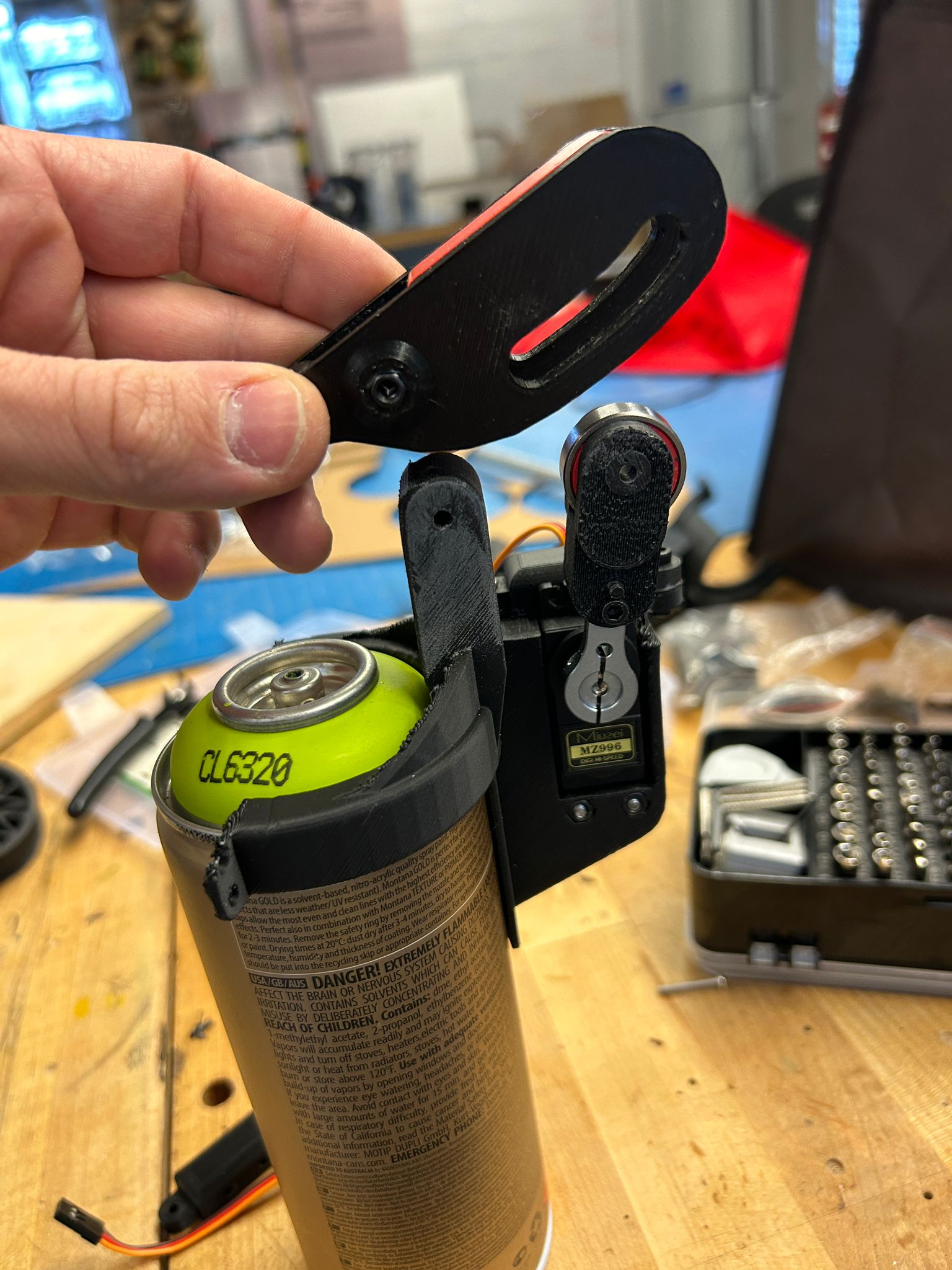
that bearring would be pushed closer to the center of rotation of the lever and since it is higher than the center of rotation, would push the lever down. the benefit of this system over the gear, among many other reasons, is that i only need 13 degrees rotation of the servo motor to actuate the spray can. this increases the accuracy and speed of the actuation, while not wearing out any 3d printed parts.
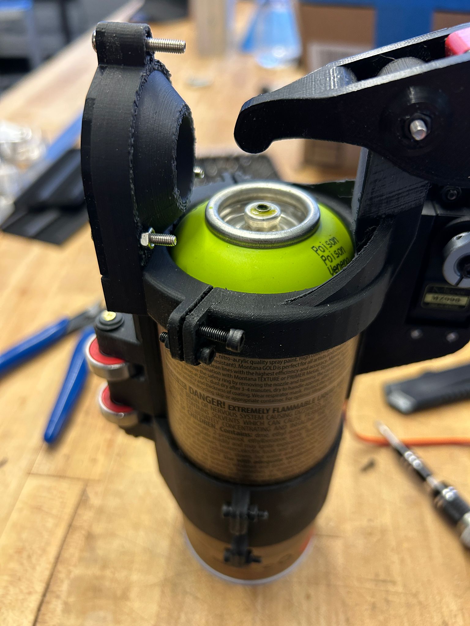
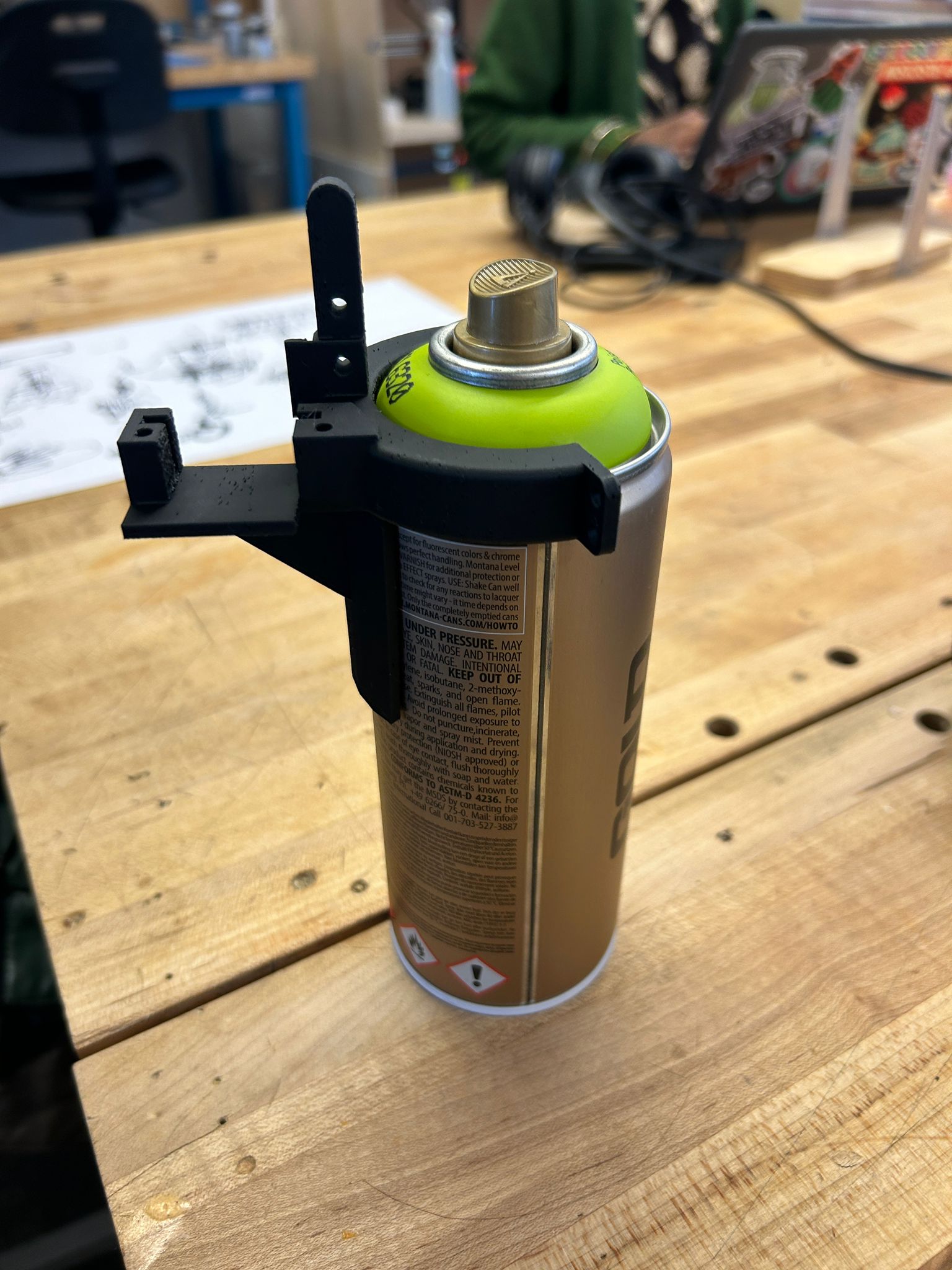
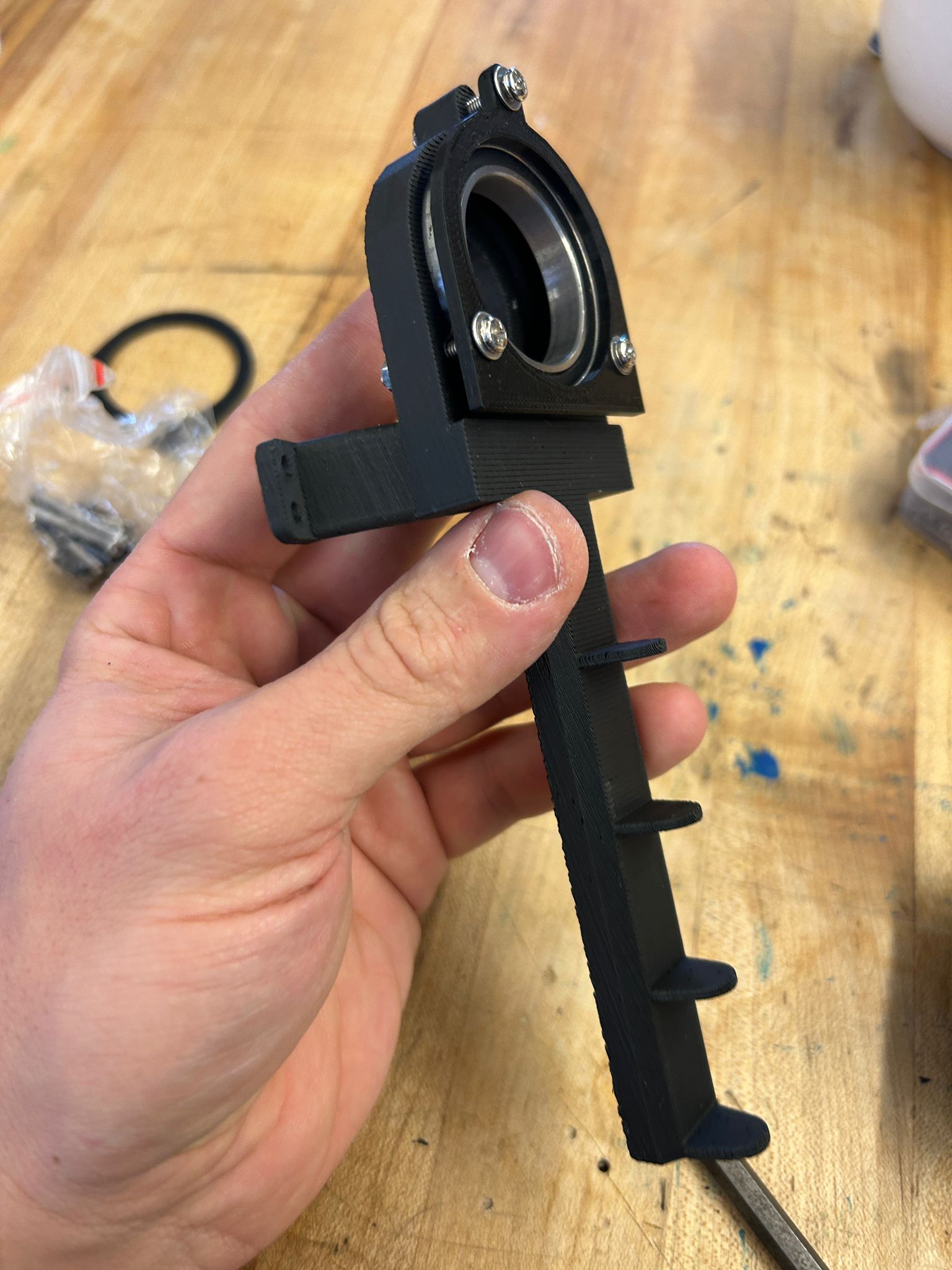
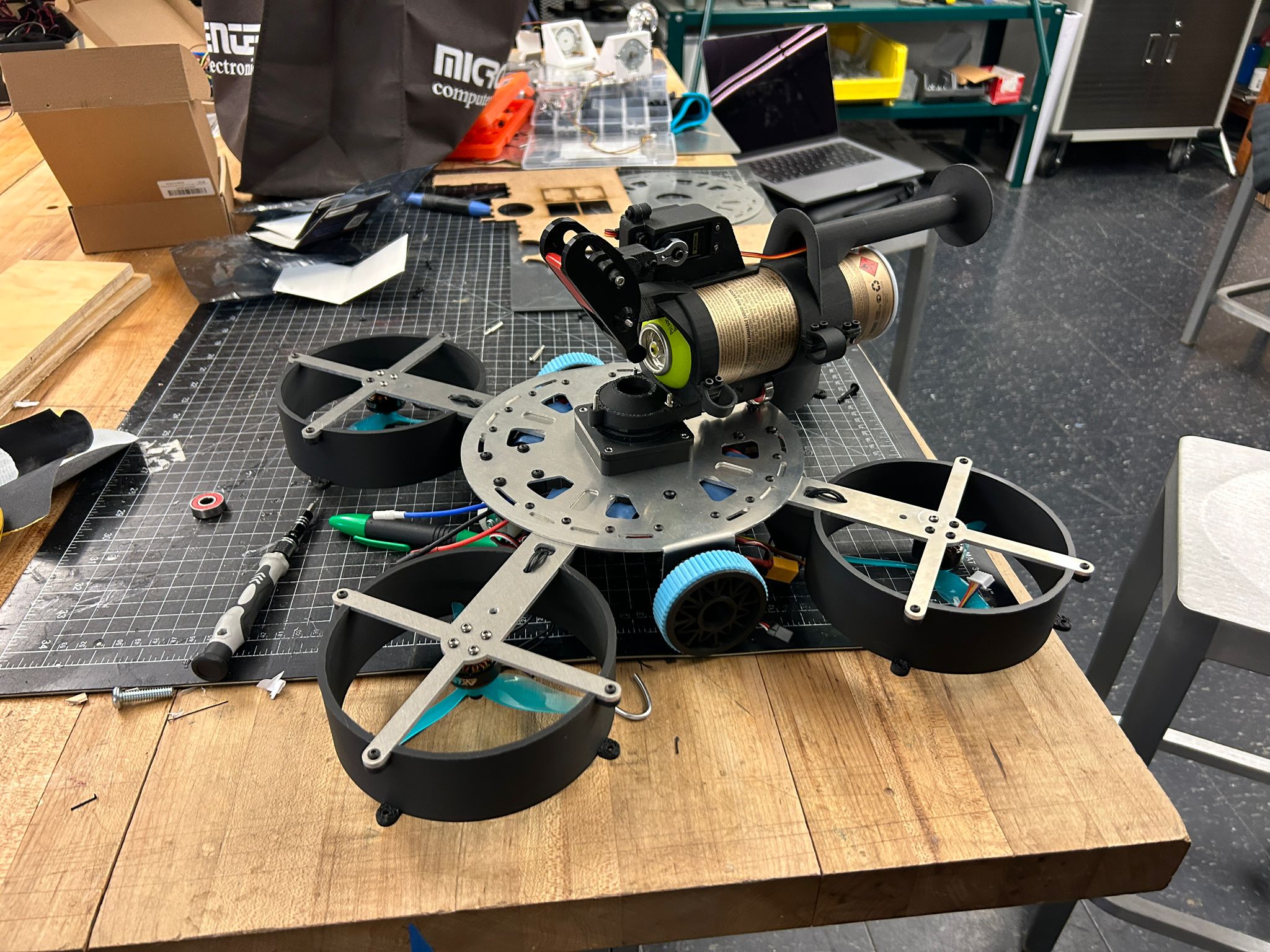
additionally to the bearring in the back, i re-designed the front part of the mounting mechanism that is holding the rotational bearring to keep the spray can perpendicular to the ground, and extended the pole to add another set of bearrings, that should enable to spin the can with less friction on top of the vehicles top surface.
and here it happened, it worked. after a long time of working on this mechanism (i did not expect this would work) therefore i did not go to the spray booth right away, i actuated it and it worked!
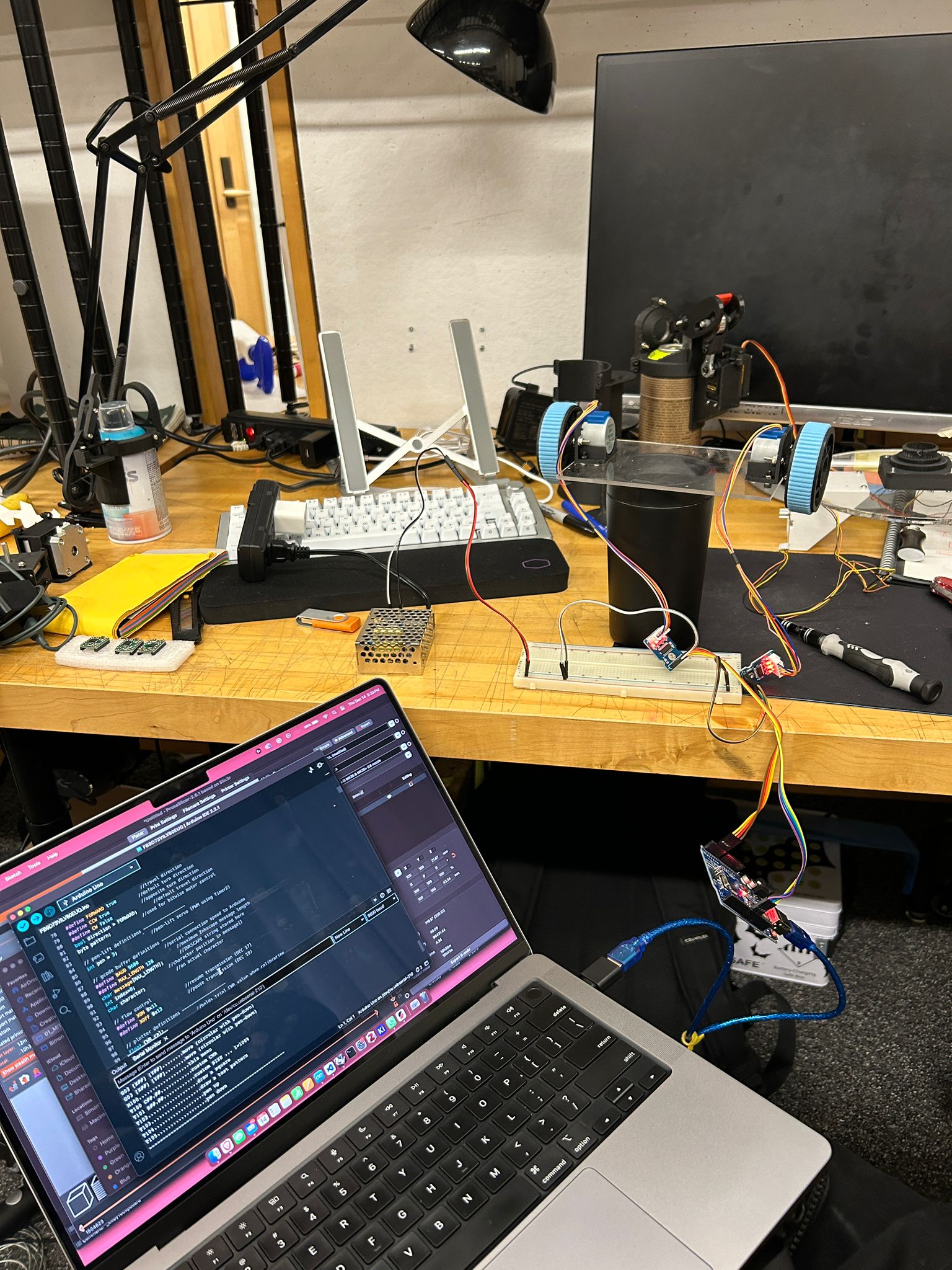
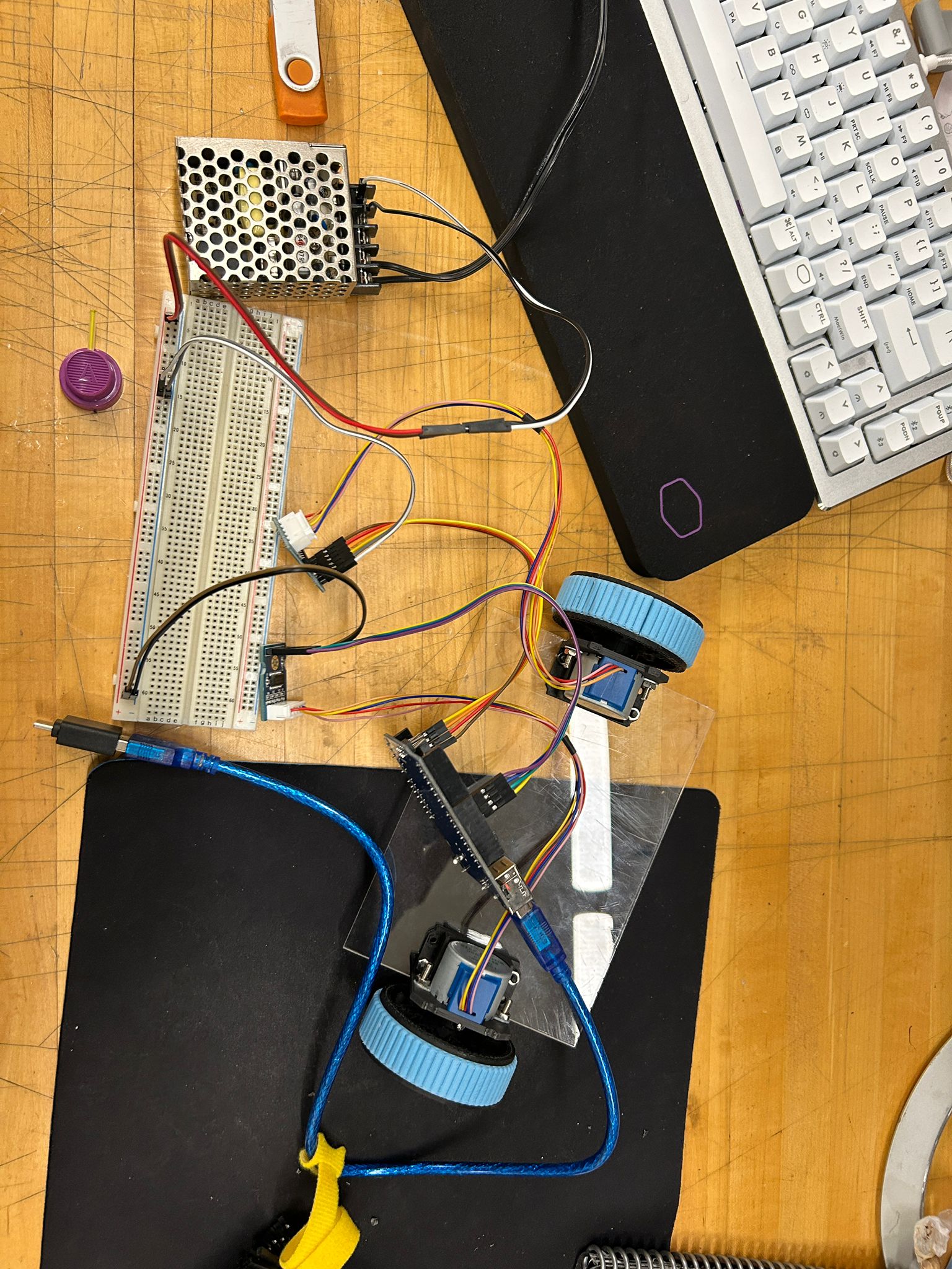
so i hooked it up to the esp32-c3, logged into the local network from the microcontroller and brought it to the spray booth!
after this i was inspired and motivated to make this all work. i knew the parts would come together. I have never designed anythin as complex as this and needed to get it working. i ended up deciding for a two motor differential drive for the actual driving mechanism of the car, since it would only require two motors with motor drivers and the micro controller to run it. originially i went with small stepper motors that would run on 5v, but soon realized that the weight of the machine would need something more powerful and stepped up to 9v and later 12v motors.
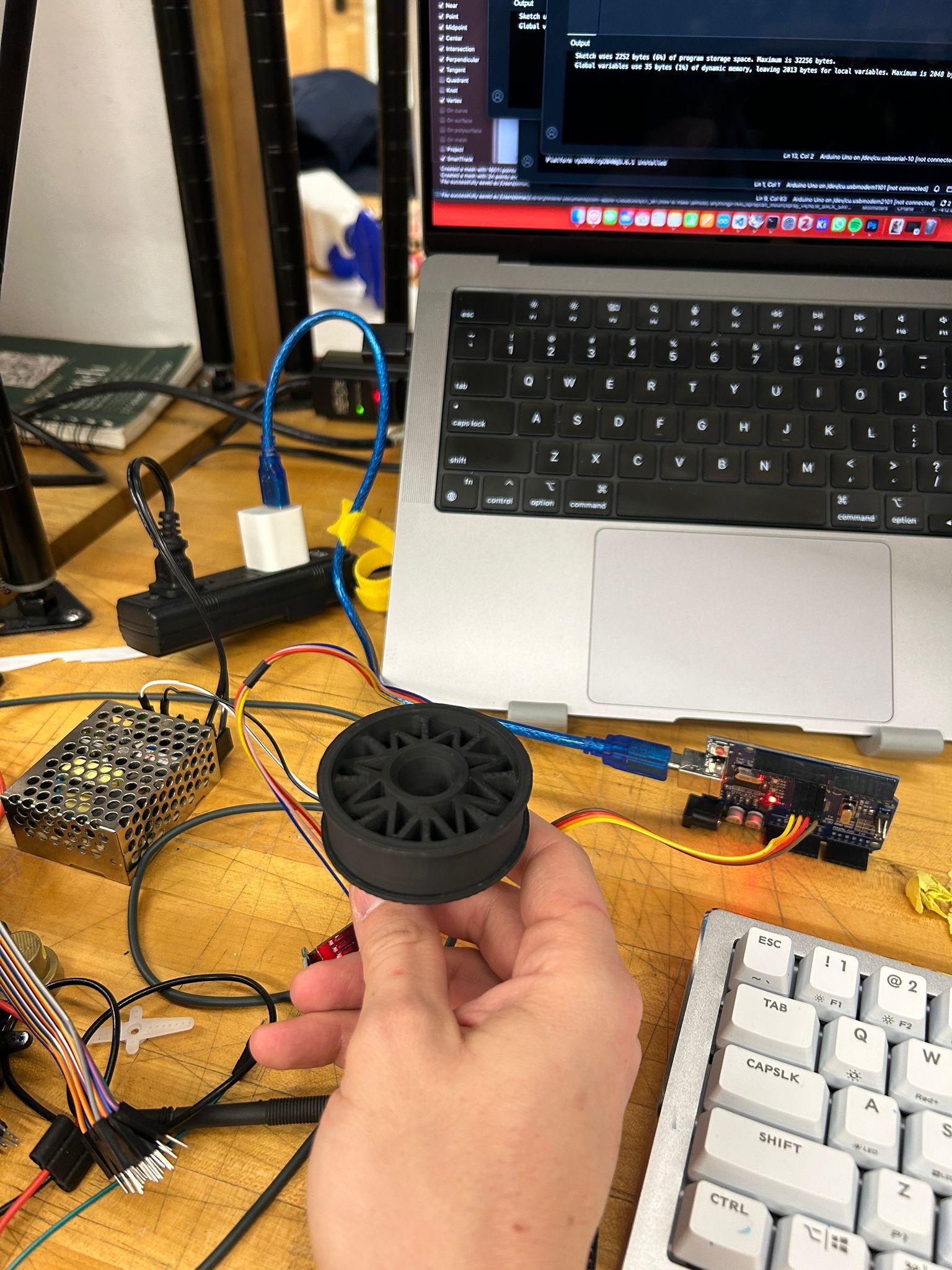
since i made more complex wheels earlier, i thought it would be silly to purchase simple ones now, so i decided to design my own pla wheels.
and since i loved the texture and sticky feel of the OOMOO by Smooth-on that we used in the molding and casting week, i decided to design my own
thread for the wheels, unroll it and print a mold for it.
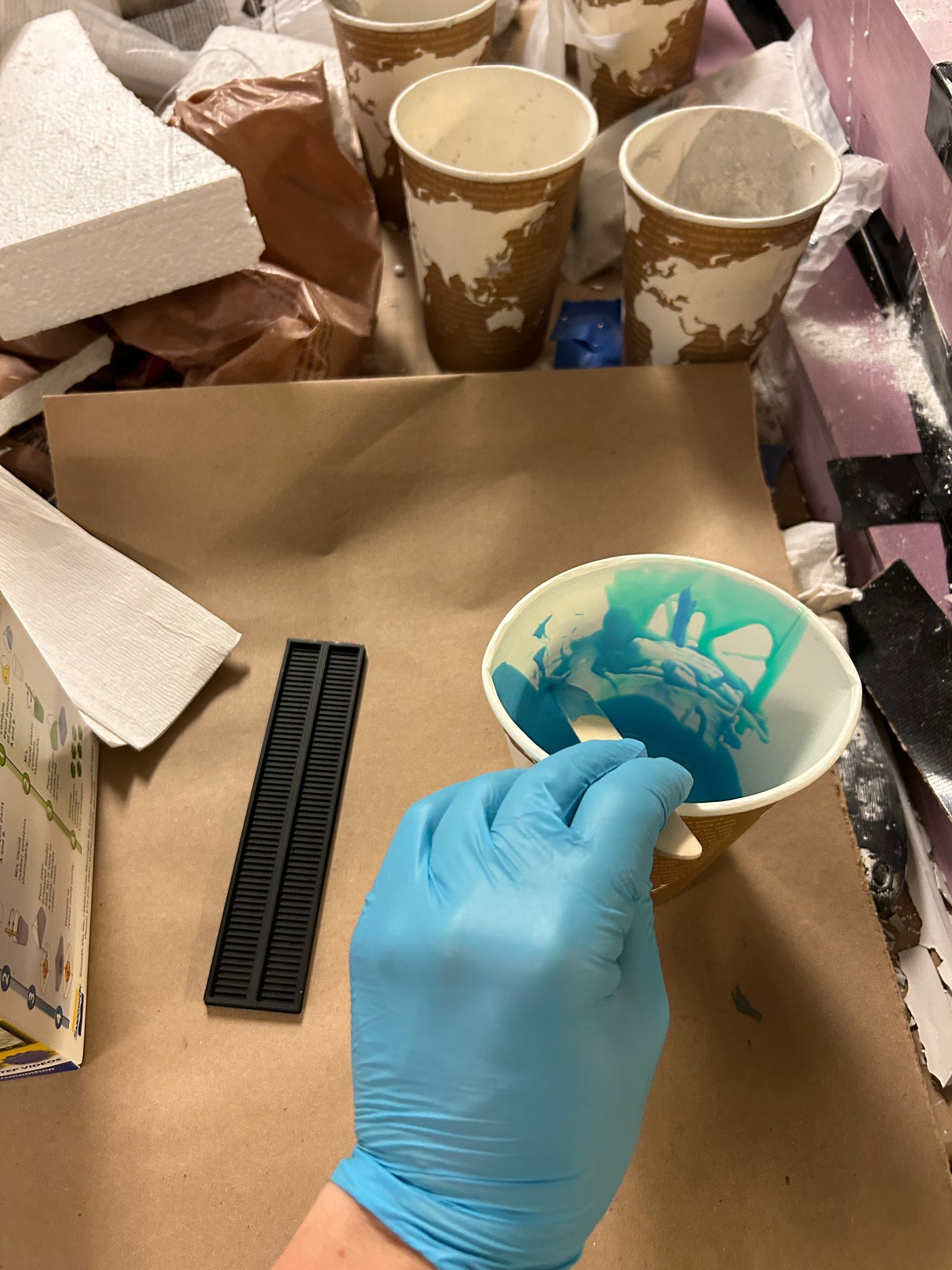
i used the same ratio of 1:1 for the two component mix and made sure i don't get too many air bubbles into the silicone elastomere while mixing it.
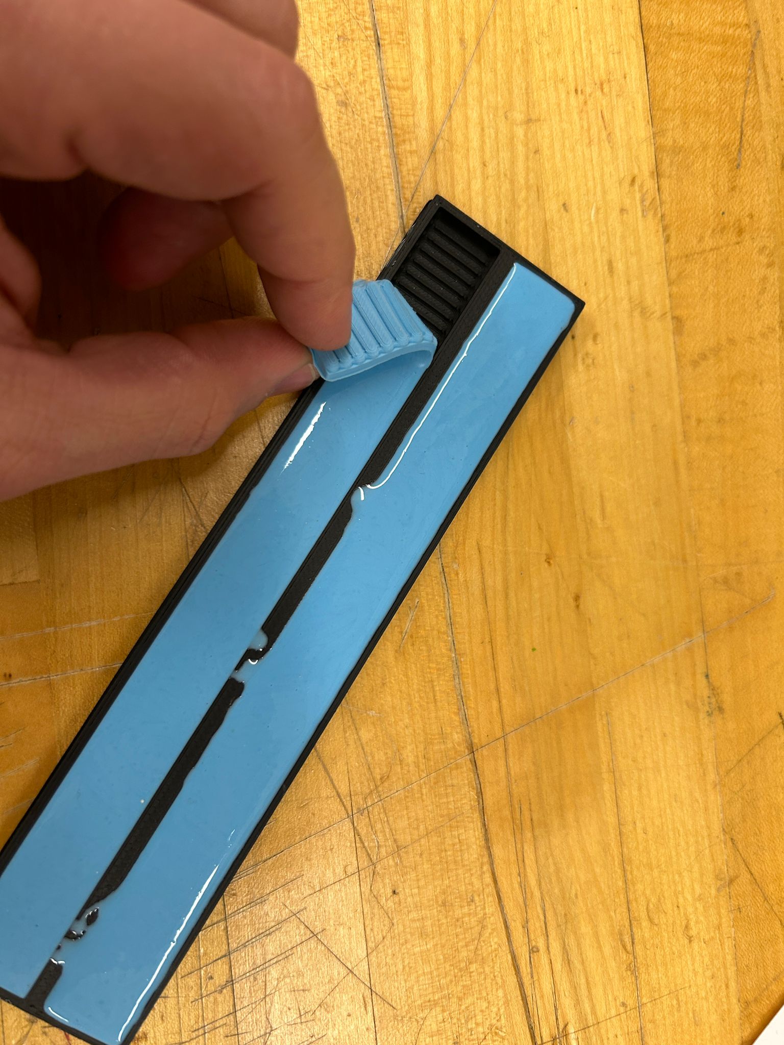
after about an hour the part was set and ready to be taken out. it is super sticky and would be perfect for my wheels
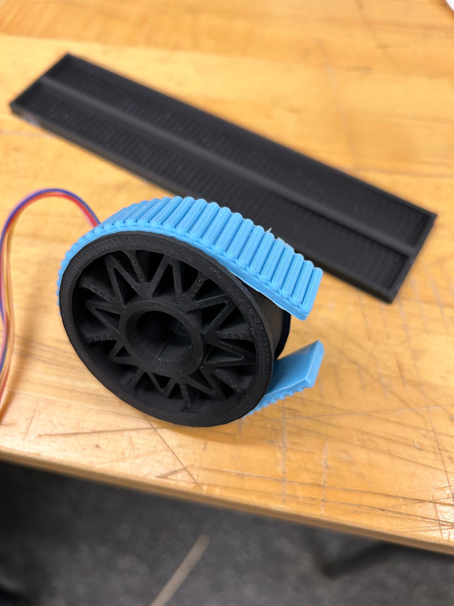
since i designed for it, it fit perfectly into the wheels and would sit into the recessed part of the PLA print. the bigger issue ended up being that almost nothing wants to stick to OOMOO (which is what makes it to such a great mold material)...i tried everything, from white glue, to hot glue, to super glue. what seemed to work, was a two component super glue i got from mateo in my section, that would set after many hours drying.
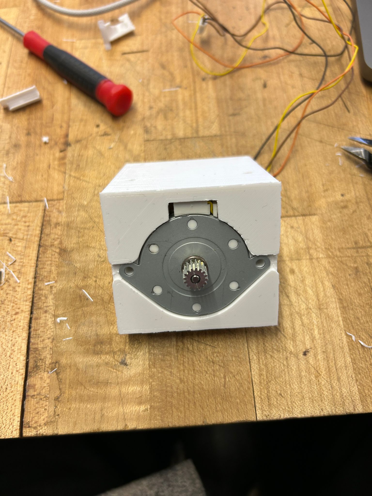
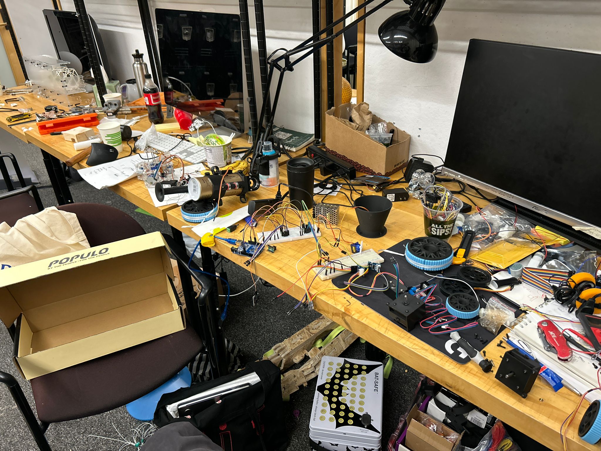
here is when it began...me trying to get the wheels to work... i tried a variety of different motors i found in the shop and in discarded machines around campus...
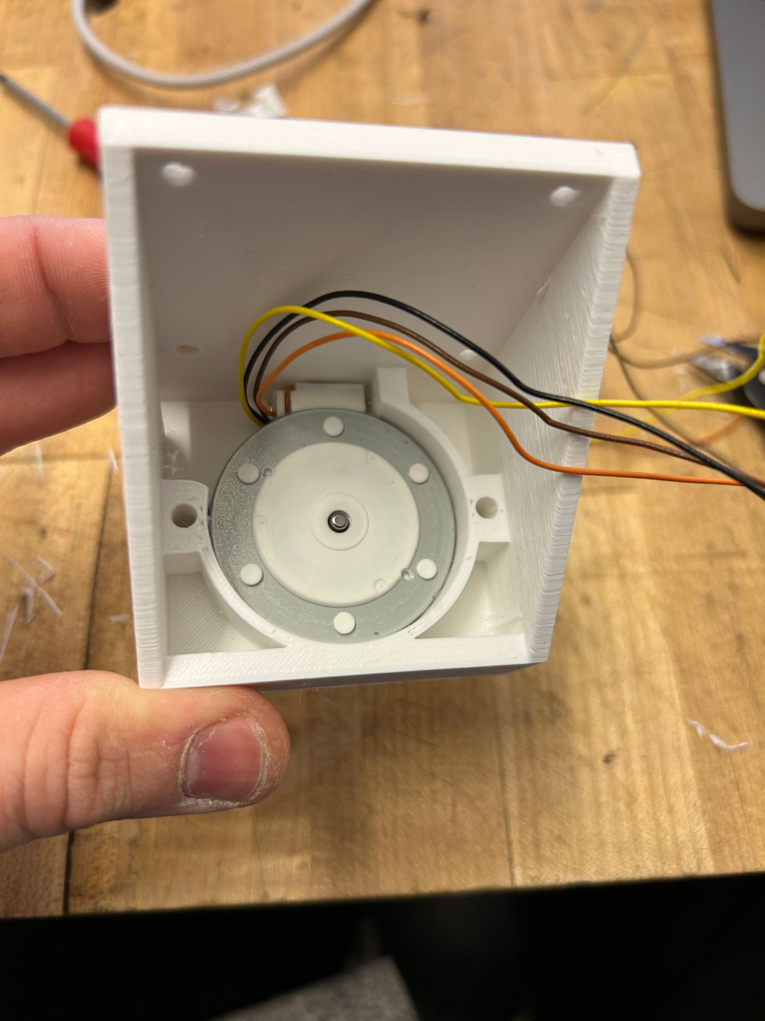
i thought these ones would be strong enough to do everything i wanted them to do, and they seemed fast... so i designed a mounting bracket for them that would consider the cable management in the back
so i tried a bunch of different stepper motors... why steppers you ask? good question...i think i wanted something that is accurate and has enough torq, but i guess many other motor types would have given me that... this might have been my downfall in the end...
more motor tests
more tests
with wheels
with tape
and finally i resorted to the smallest version with the smallest wheels (for the sake of weight and space)
and made it drive around and turn
while the bigger wheels would have made the robot a lot faster, it also made it a lot bulkier, and with the thick acrylic plate i experimented with, it would never drive up a wall. but i wanted to leave the option open just in case something goes wrong... and it would
i would put it all together as a test version and realized that, not knowing what exaclty went wrong, but the motors would stop working, and if they did work, they would barely be able to move the weight of the robot... (future me should look back into this but at the time i was just frantically trying to find a solution...and i had enough different motors..)
i thought getting trained on the co2 laser would be a good idea in any case since it would allow me to make the frame out of aluminum instead of acrylic, which would look cool, be lighter and stronger.
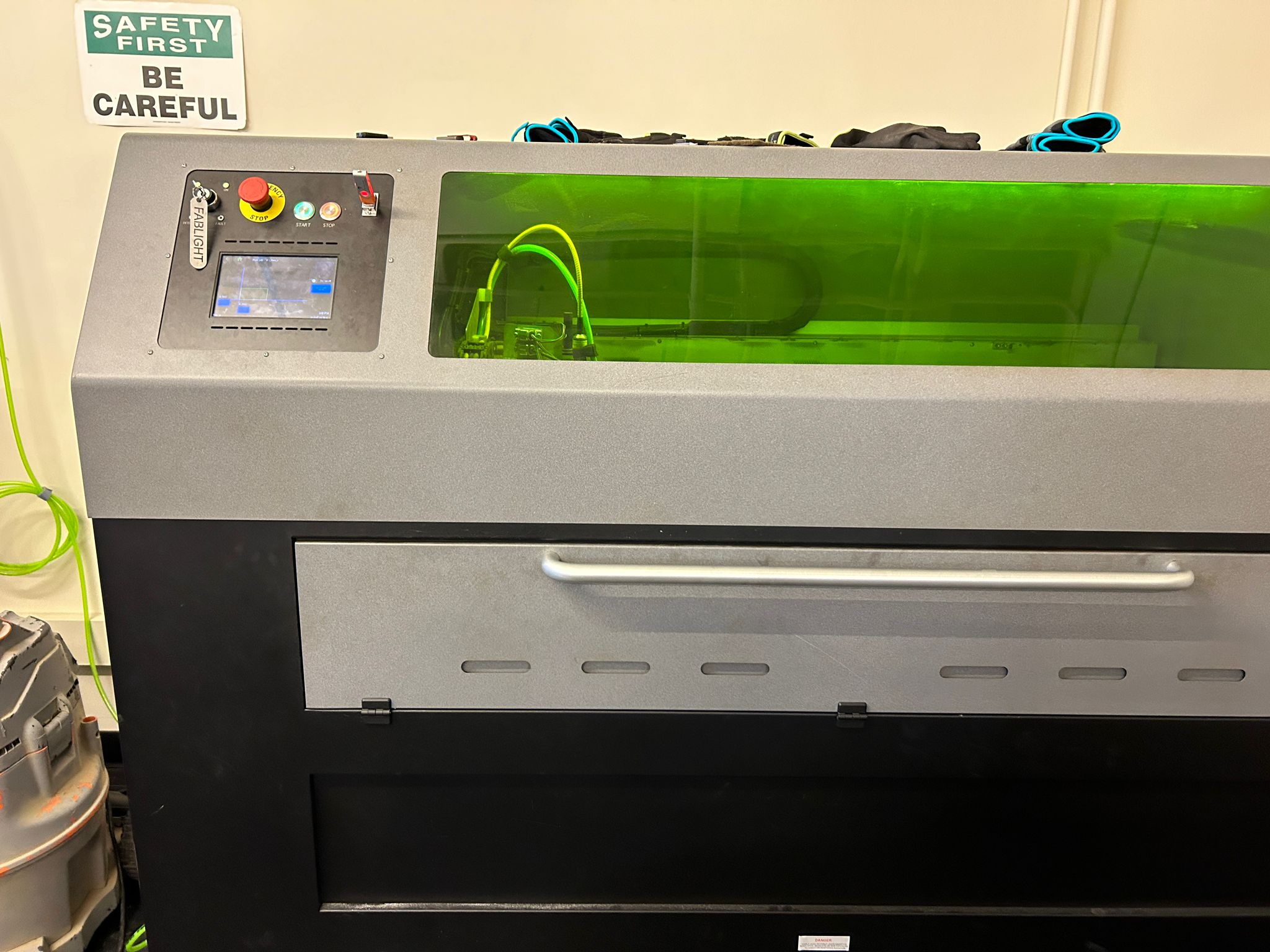
and to my pleasent surprise, it is easier and more intuitive to use than a normal laser cutter. you simply export your line drawings as .dxf (if from rhino, make sure you use the 2007 polyline preset) open it in the software that comes with the laser cutter, where you dont need to specify anything but the material and the material thickness, manually draw some 0.5mm tabs around you pieces so they don't fall or twist which could interfere with the laser head, export it as the machines specific file type, load it on a thumb drive, bring it to the machine, load your material and clamp it down, set the x-y home and press play. it cuts as fast as a normal laser cutter, but no smoke, no dust, nor burnmarks...just pure joy!!
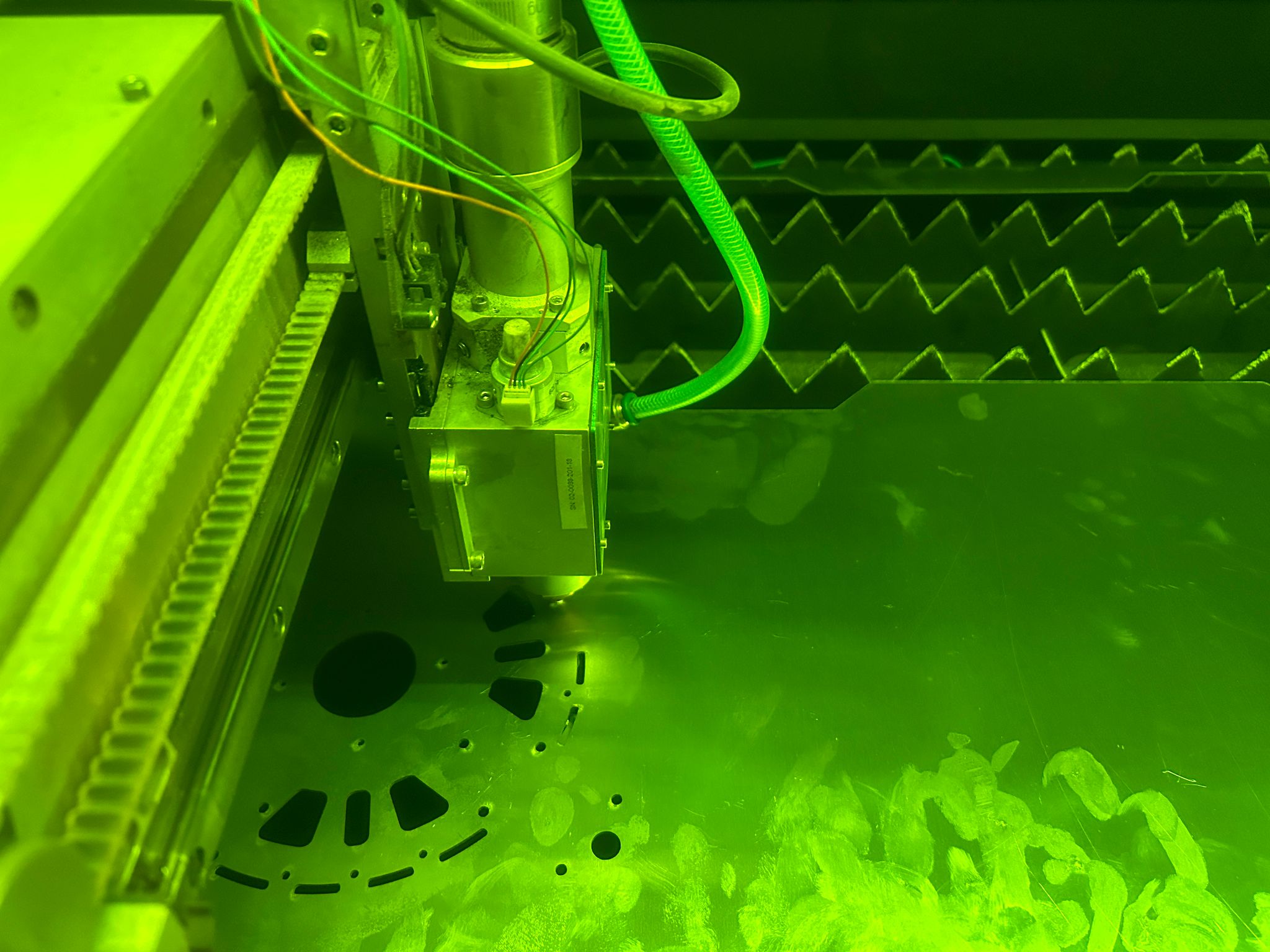
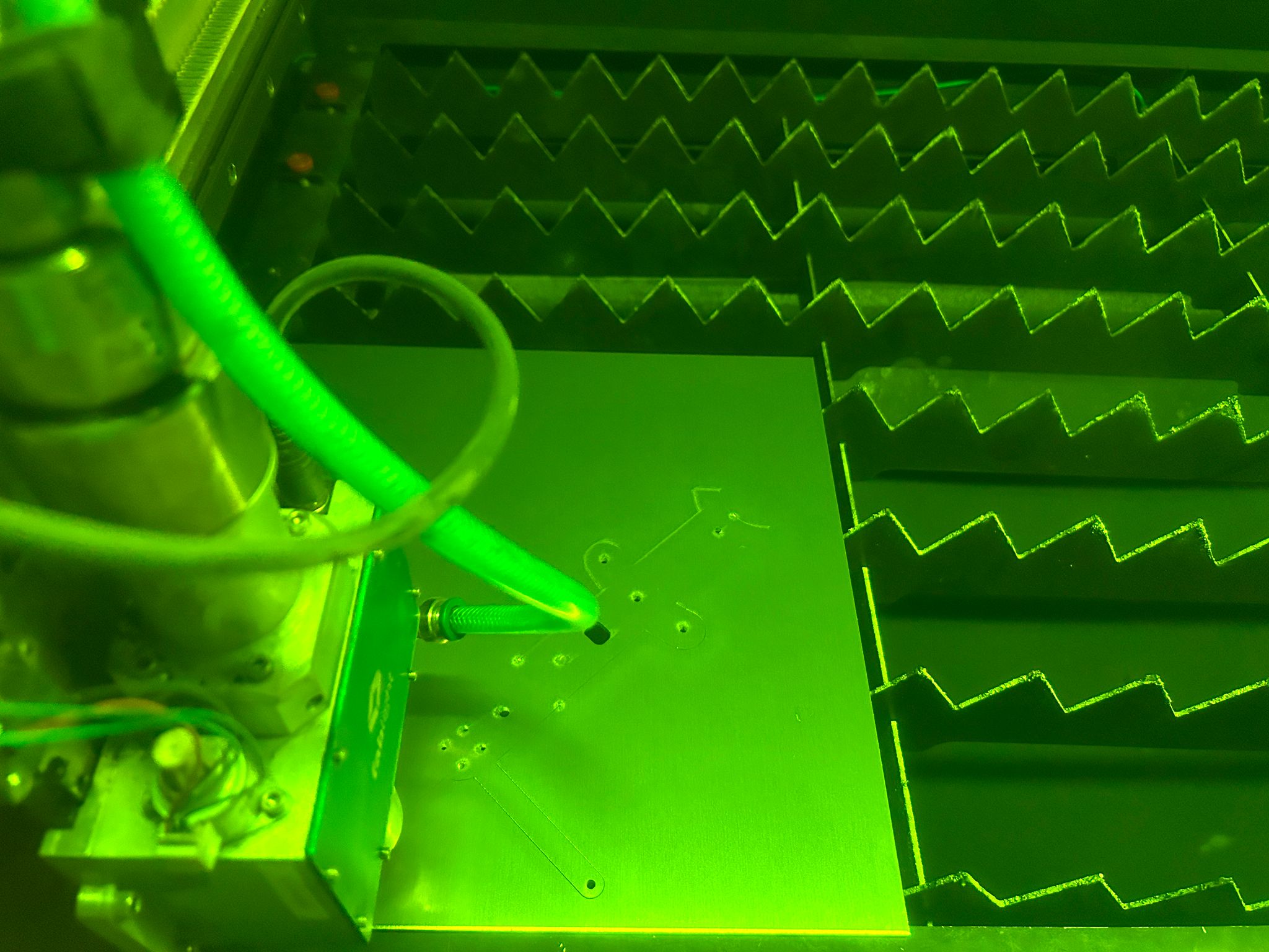
and the result is fascinating. i printed some parts in 0.125" 6061 aluminum, some in 0.063" 5051 aluminum. as i later would find out, the 6061 is cheaper but briddle, and does not like to bend at all, while the 5051 is apparently closer to pure aluminum and has at least one good bend to give.
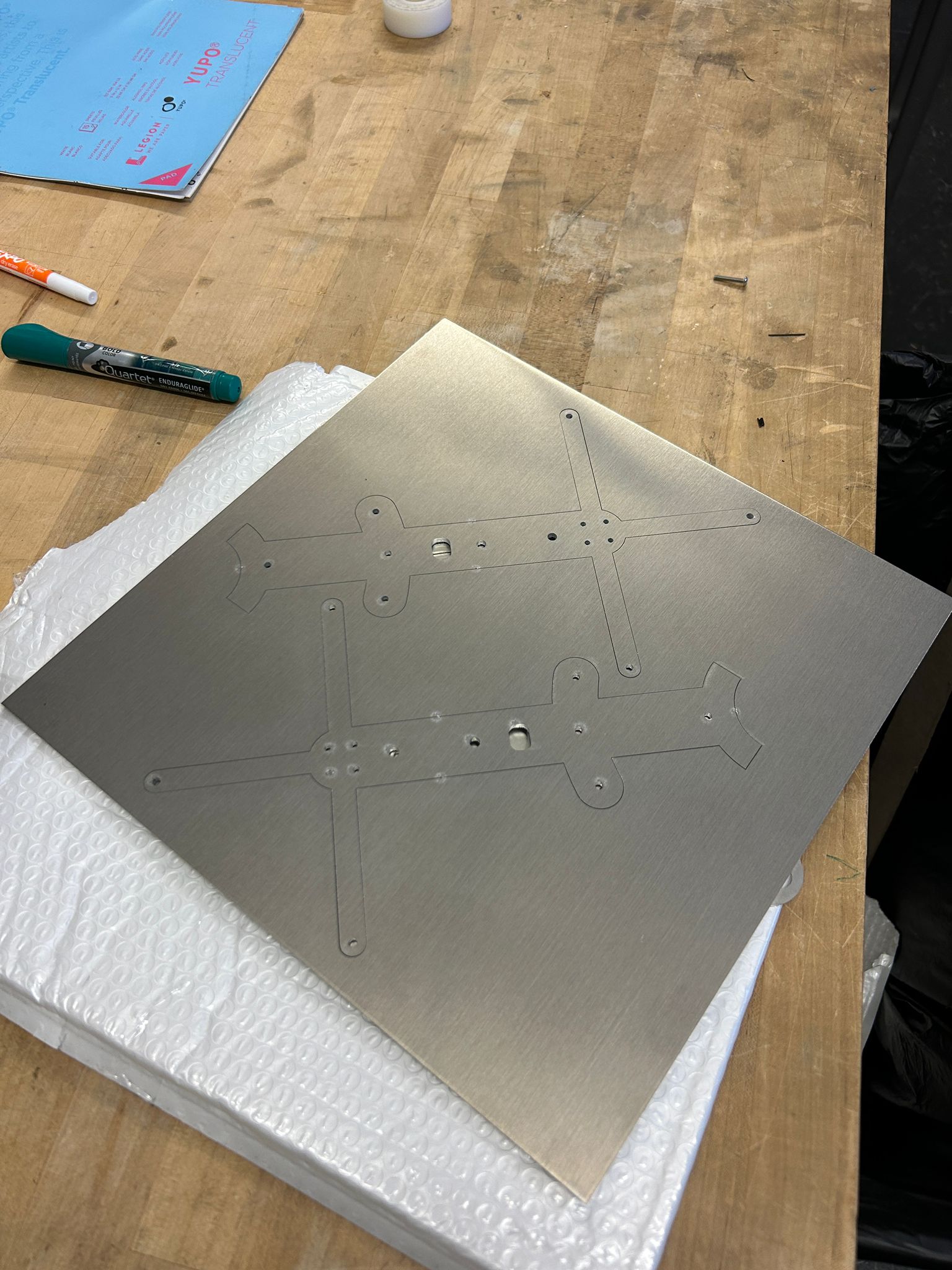
taking it out of the laser, the pieces would still stick to the sheet you cut them out of, but a little twist or knock would break the super tiny tabs and the pieces would fall out.
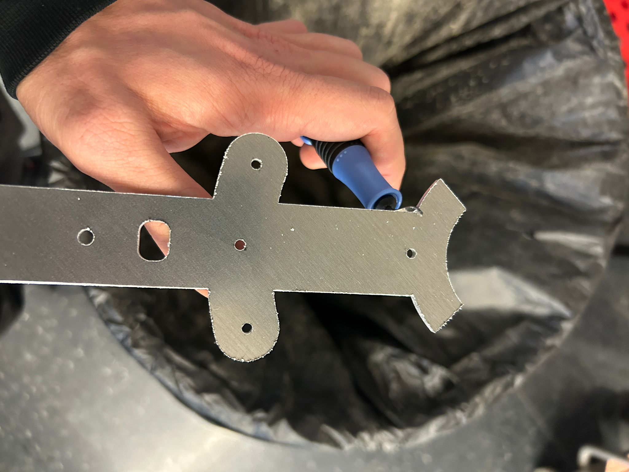
since the laser uses around 70-100 psi (depending on material and thickness) to blow the molten aluminum out the bottom while cutting, there is a slight burr that one can feel when touching the underside of the cut material. a de-burring tool is what i used for this (for the first time) and it is definitely satisfying and fun to do. it is basically a hardened blade you run at a 45 degree angle across the material and it just cuts away all the access blow out material
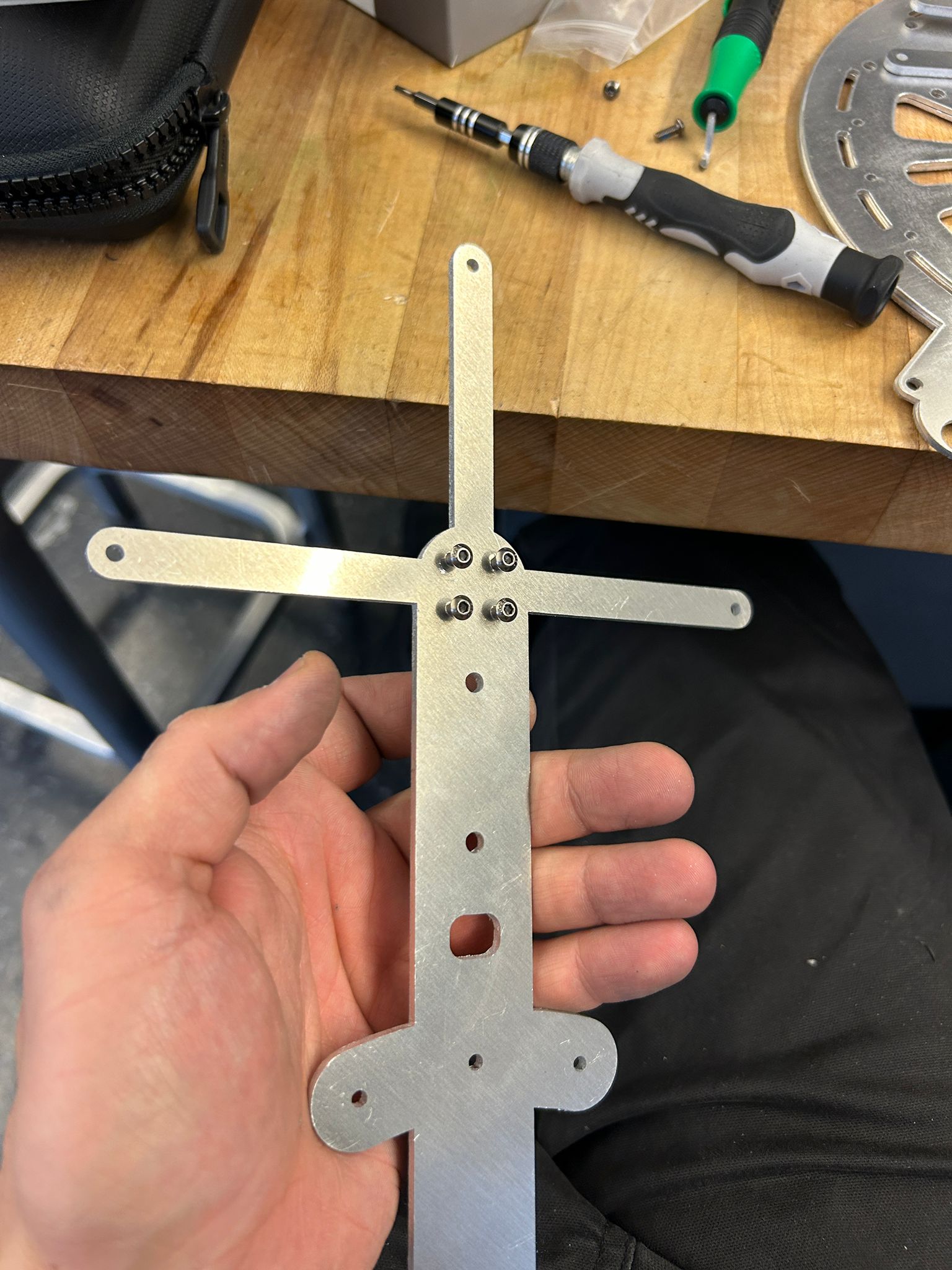
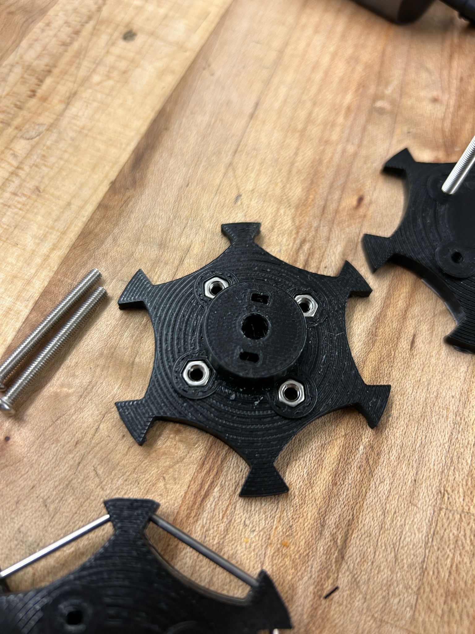
next, i threaded the holes that i would mount the drone motors to
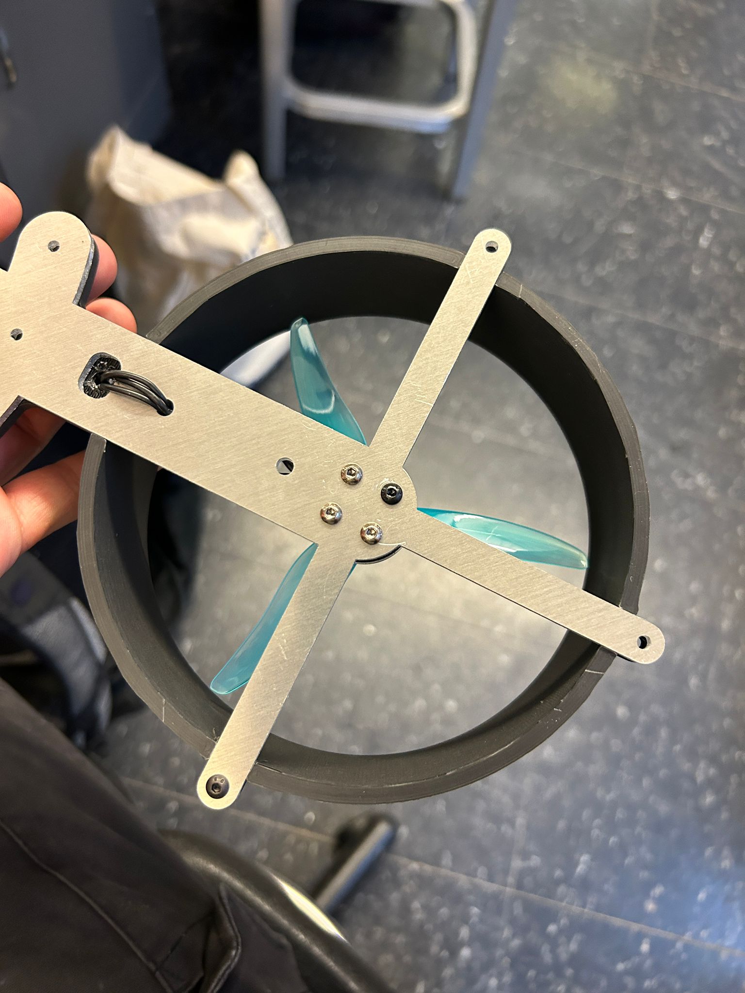
clipped the drone motors with the aluminum brakets into the pla finger-safeguard ring
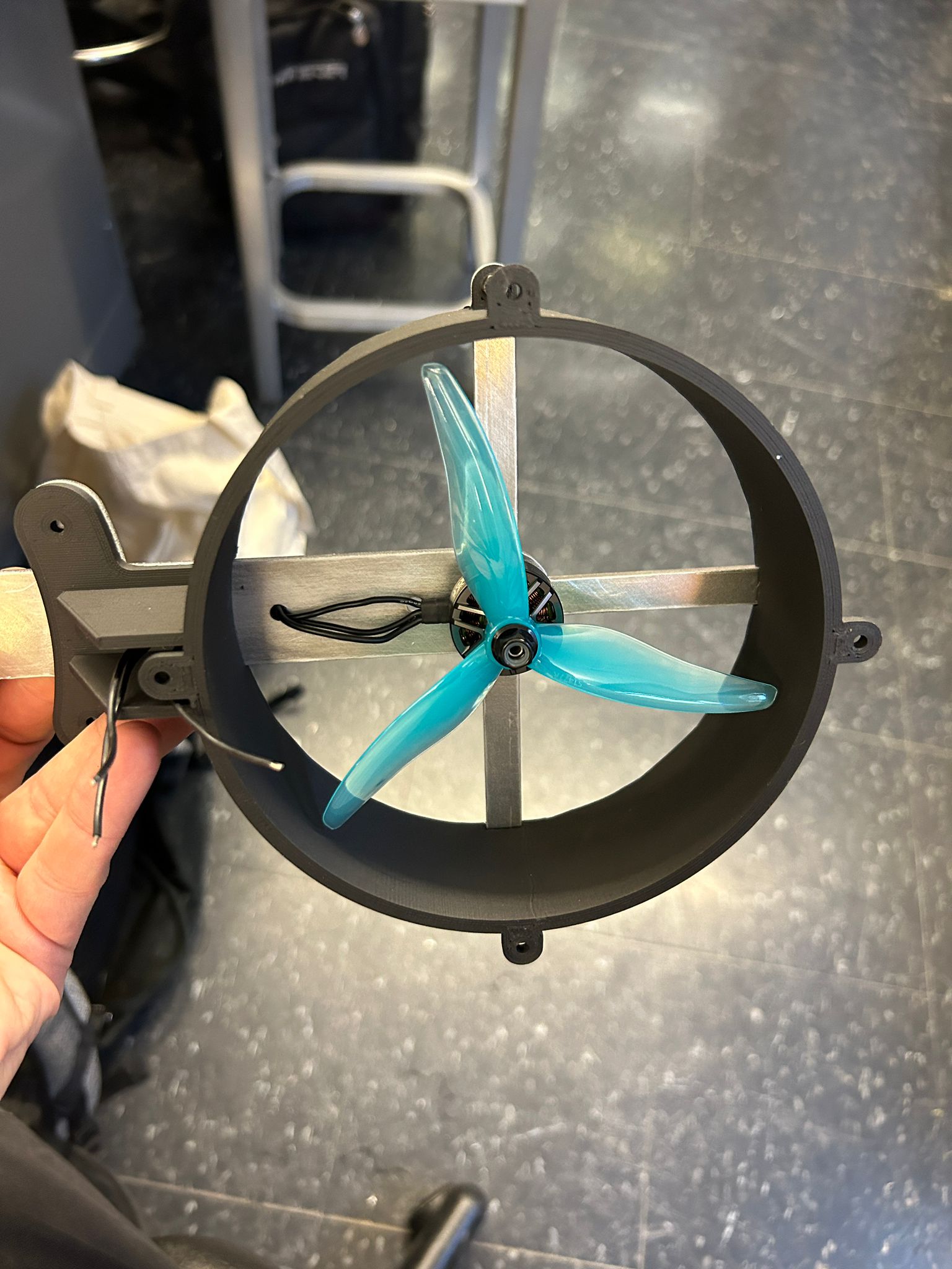
run the wires through the holes
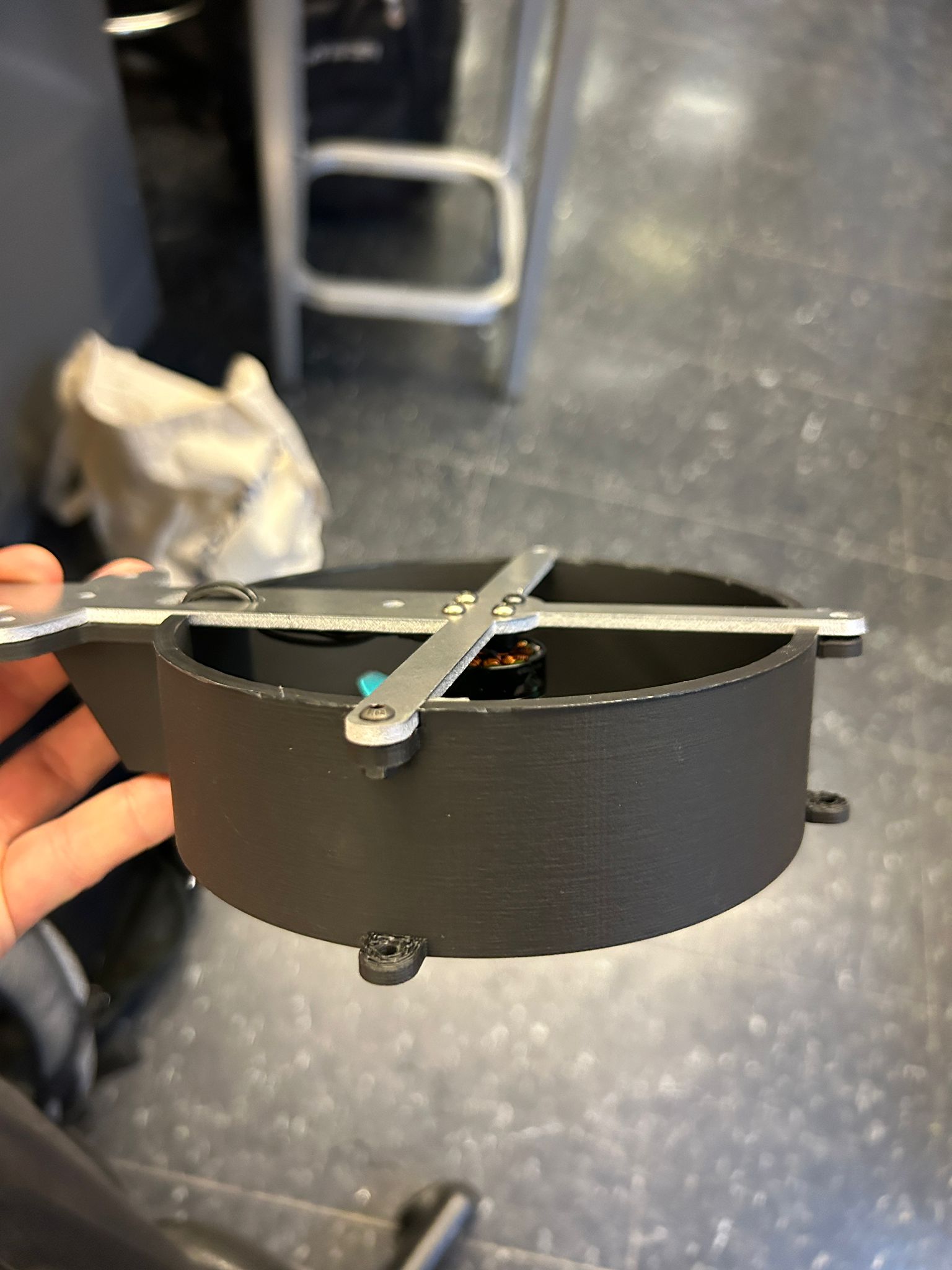
and screw them together using short M2 screws and a drop of blue lock tightener (basically a like a nylon that you can put on the thread of the bolt, let it dry and when you screw it into a nut it locks because of the extra material)
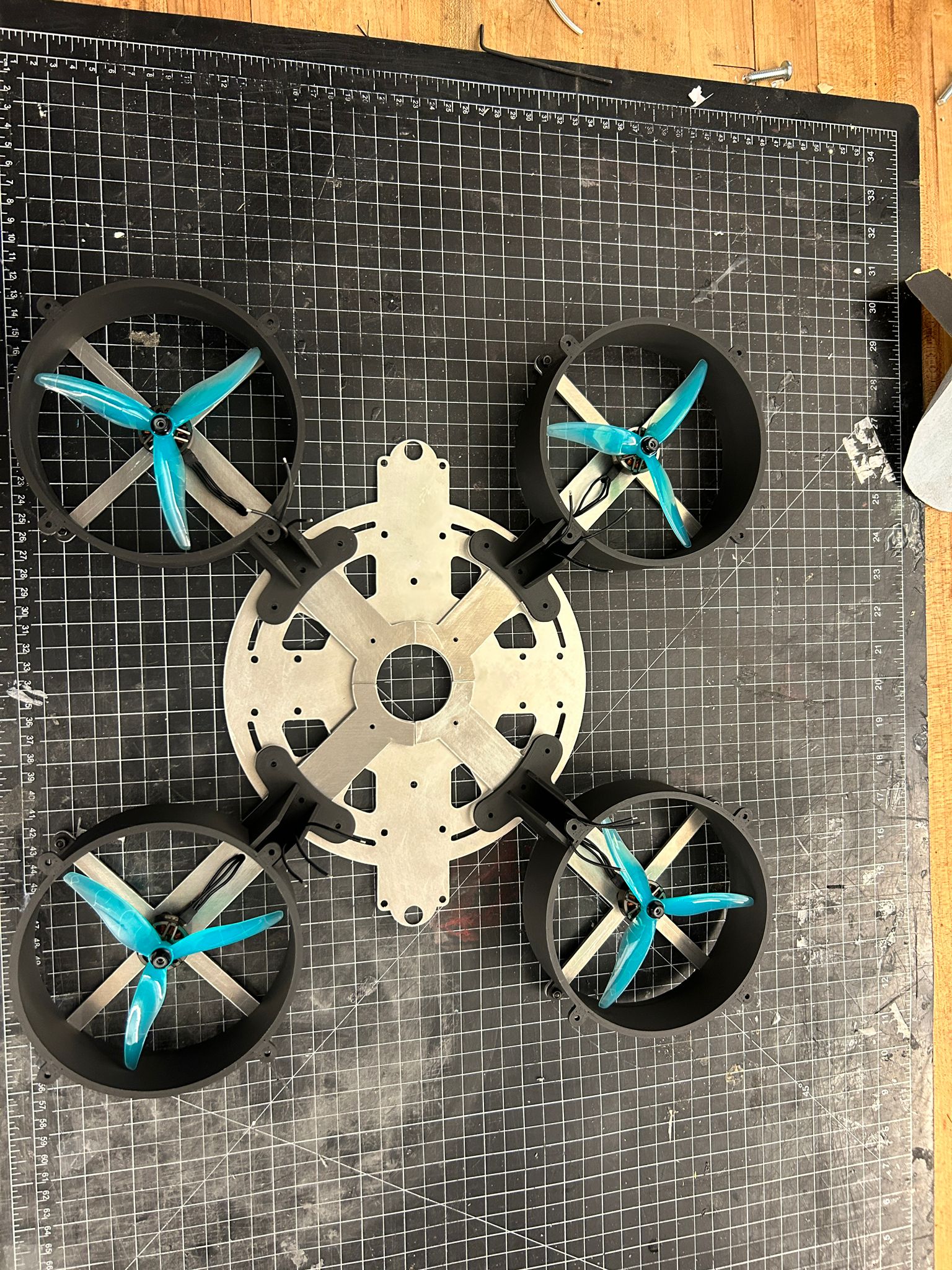
doing this four times resulted in this
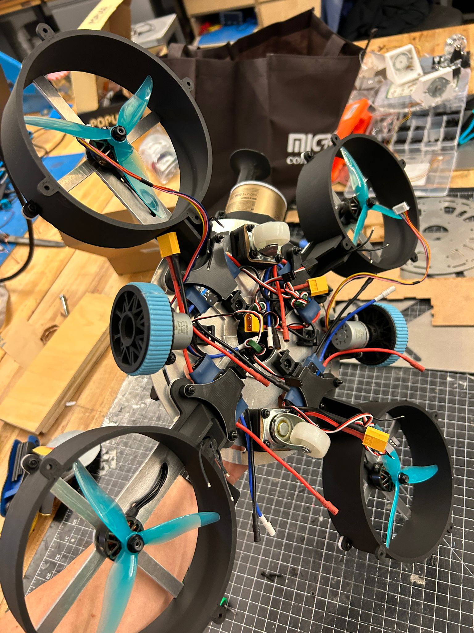
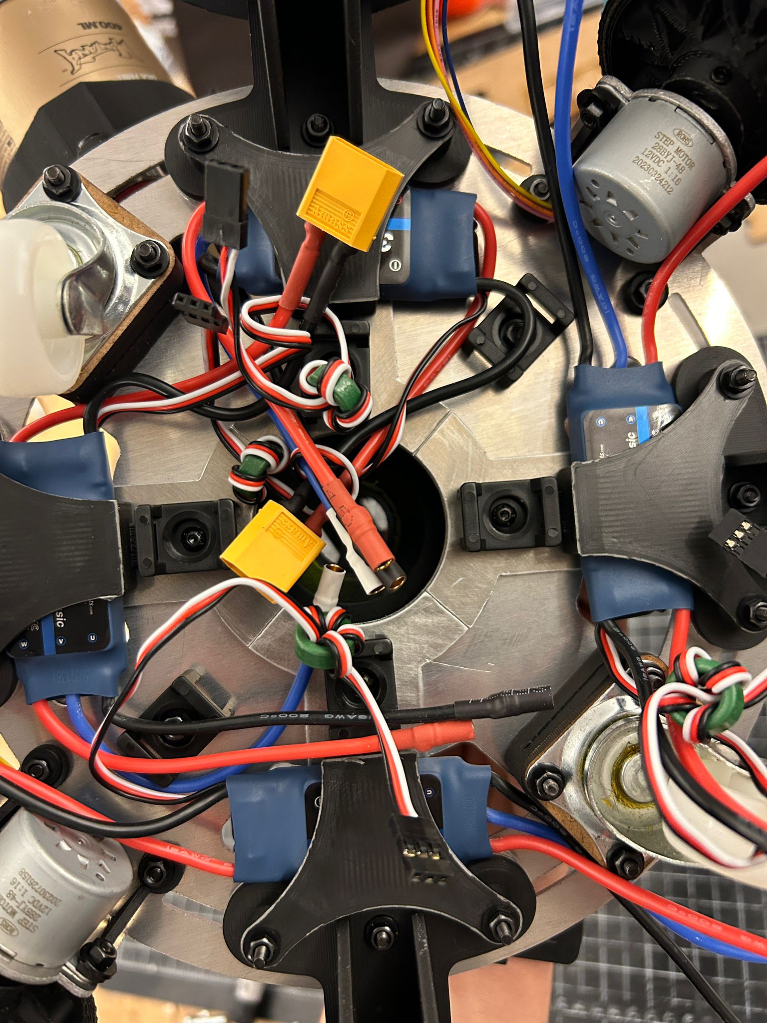
i had some brackets printed before hand that would allow me to mount the ESC for each drone motor to the brackets of the finger-guard on the underside of the vehicle
then went ahead to add the set of stepper motors with custom wheels as well as the tiny swivel wheels i picked out of the garbage behind a lab
and there it was... from this moment on i was haunted by many days of not getting anything to work