#8 candle snuffer
this week i wanted to start with a simple input device, and decided to look into simple photo resistors. they are, as the name says, resistors that are light sensitive. if not exposed to light, they can have a high resistance, while, the brighter light they are exposed to, the lower their resistance.
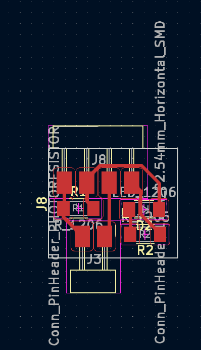
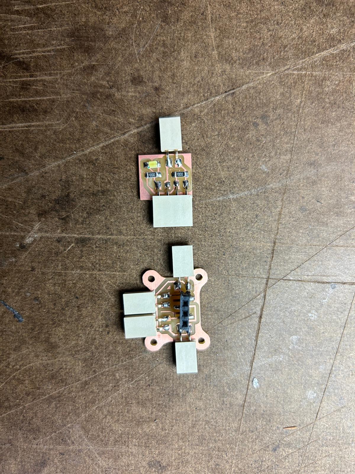
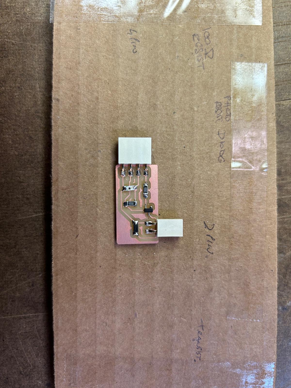
I decided to make a small pcb, that simply allows me to connect an analog sensor, like the photoresistor, and added an additional led on the board, that could be triggered through a digital pin depending on the analog input
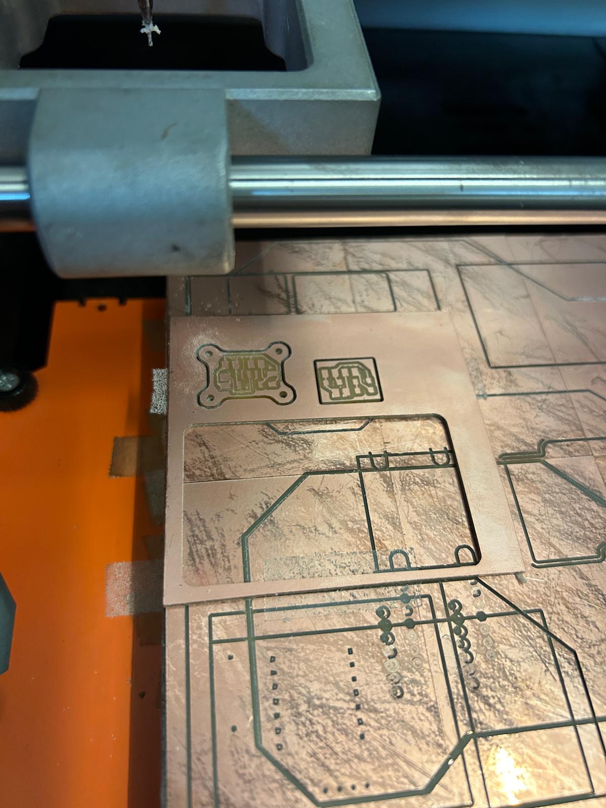
so i decided to make some new pcbs to test the idea.
the original idea was to create a pcb that functions with a microcontroller, and another one that would be a completely analog circuit.
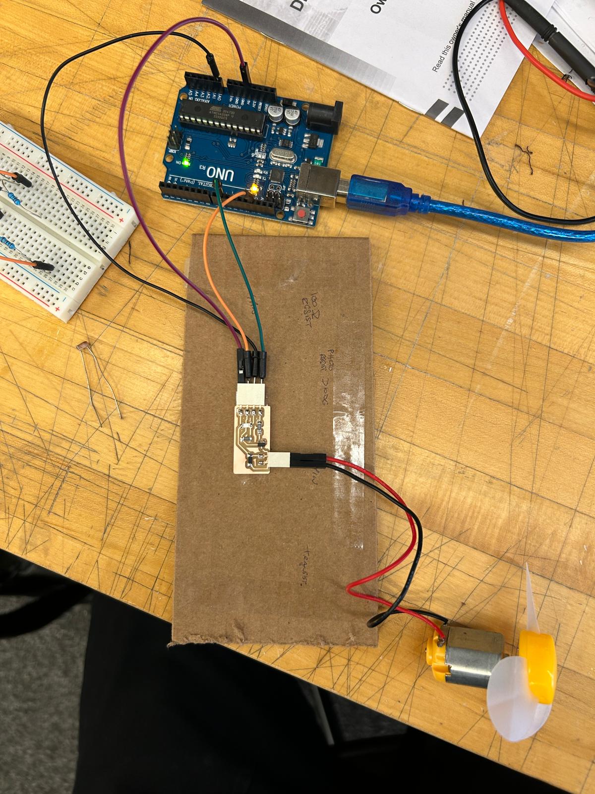
in the experiment, i connected my new pcb to my esp32c3, using one analog, one digital,
the 5V and GND pin. I would be reading the analog resistance difference through the analog
pin, and would send different blinking signals to the digital pin, that is connected
to the led on the board. (this example was running a micropython script through thonny)
i use the phone led to test the threshold of the analog signal, so it does not react fully
by the environmental light in the room.
from machine import ADC, Pin
import time

photoresistorPin = ADC(4)
ledPin = Pin(5, Pin.OUT)
threshold = 5

while True:
    lightLevel = photoresistorPin.read()
    print(lightLevel)

    if lightLevel < threshold:

        ledPin.on()
    else:
        ledPin.off()
and based on the led example, i thought it would be fun to have it react to a flame of a lighter, maybe eventually of a candle. So if i connect an led, it will turn on when the candle burns down, but is shut off as long as the candle burns.
I tried looking at the serial plotter in thonny, but it picked up a lot more noise than
the previous arduino code did, so i brought this back into arduino and used/recorded the
serial plotter in arduino.
here is the code i used in arduino:
const int photoresistorPin = A0;
const int ledPin = 9;
const int threshold = 100; //threshold value for light level

void setup() {
  pinMode(ledPin, OUTPUT);
  Serial.begin(9600);
}

void loop() {
  int lightLevel = analogRead(photoresistorPin);
  Serial.println(lightLevel);

  if (lightLevel < threshold) {
    int blinkSpeed = map(lightLevel, 0, threshold, 100, 1000);

    digitalWrite(ledPin, HIGH);
    delay(blinkSpeed);
    digitalWrite(ledPin, LOW);
    delay(blinkSpeed);
  } else {
    digitalWrite(ledPin, LOW);
  }
}
while i had the led turn on when the resistor was not exposed to light, which works against the internal analog function of the photo resistor, i thought to experiment with the opposite or more obvious function of the resistor. i should be able to make a circuit that can use the resistance to turn on a second device.
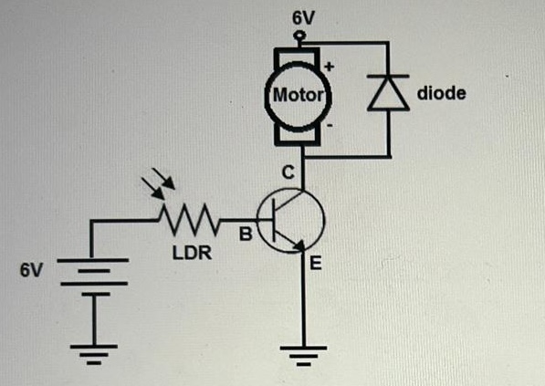
after looking into different ways to hook up leds, i thought it would be much more fun if the photo resistor would trigger a dc motor to draw power, or not
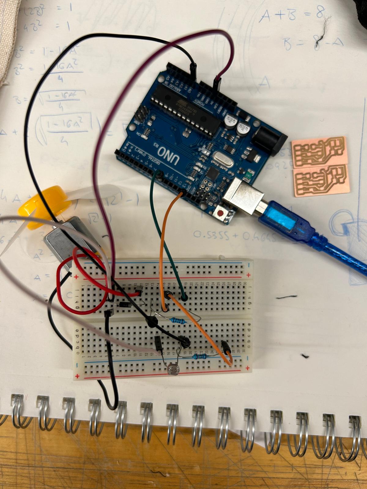
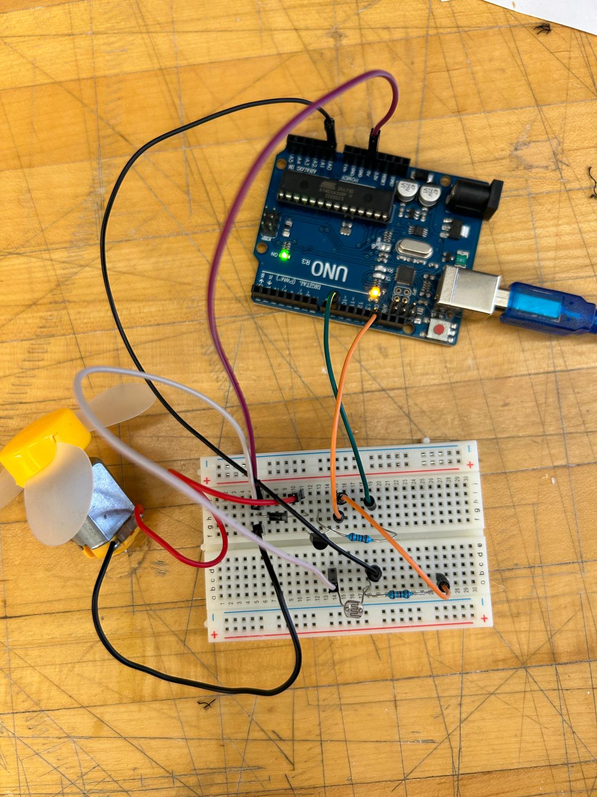
despite being a disliked component by certain people in htmaa, i decided to mock the circuit up with a breadboard, to understand and measure whats happening.
and to my surprise it ended up working well. originally i thought i'd need an additional potentiometer, that would be in support of the photo resistor, to fine tune the total resistance, almost like the threshold i set in arduino/thonny when controlling the input and output.
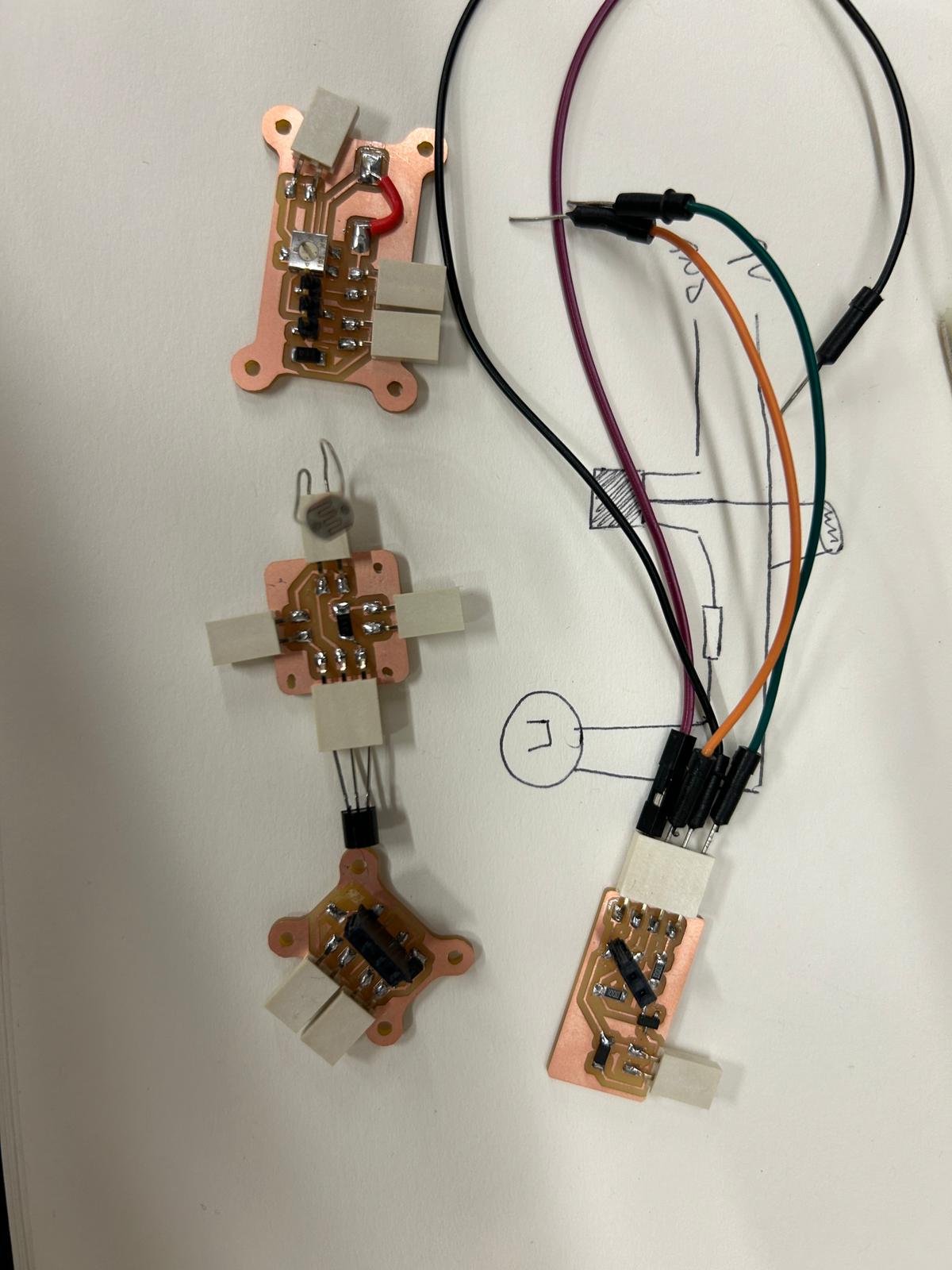
i wanted to make this into a small circuit on a pcb, and hoped to incorporate it inside a candle holder, and hoped to minimize the footprint, but something went wrong in the various attempts...
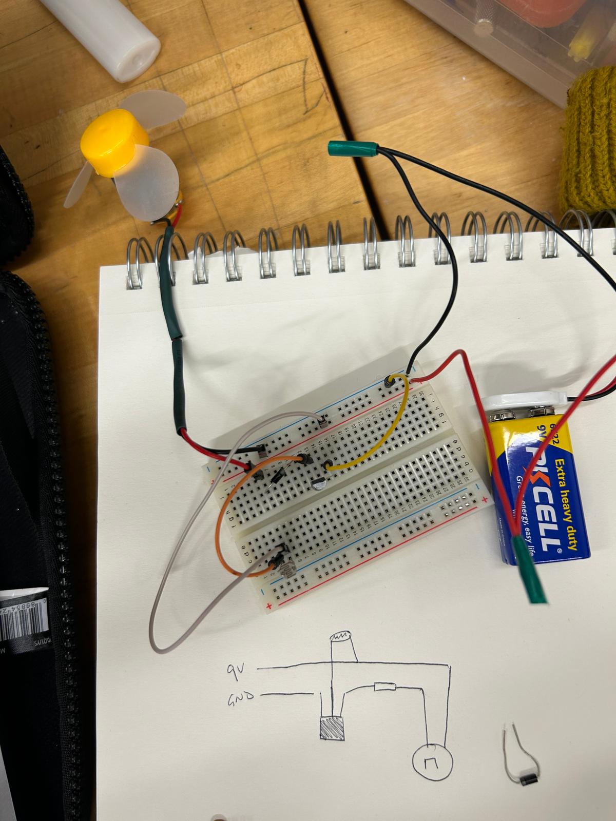
in the end, i decided to construct a small analog circuit on the beloved bread board, saw that it worked, and decided to call it a day for the night.
To be continued...i hope to make the candle holder happen and implement the analog sensor