#5 times is a charm
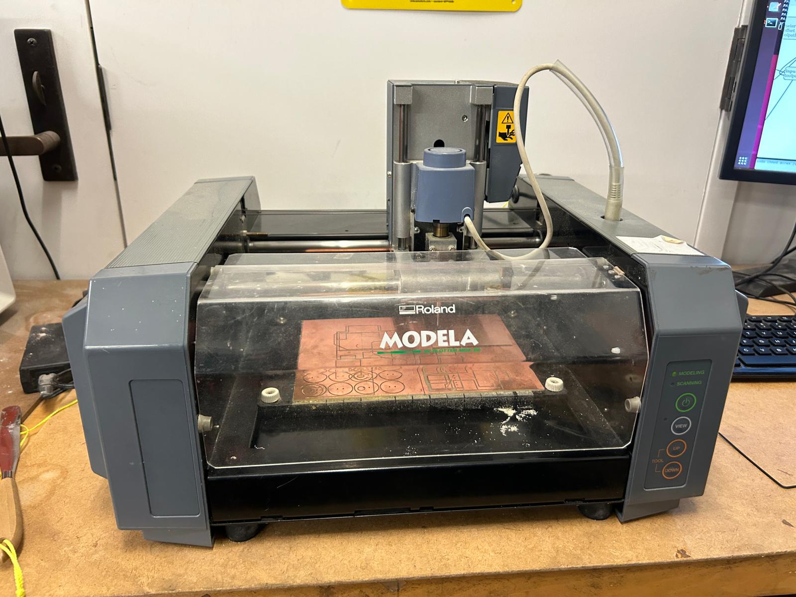
starting making the pcb physically involved understanding the milling machines and what kind of file setup would be neccesary to mill. the architecture shop gave an introduction, talking us through all the steps as well as common mistakes in the making of pcb boards. to start of with the milling, we used two different models of modela mills. on one hand there is the modela MDX-20 and the newer version SRM-20. the milling setup and control works very similar for both machines, except for the setup for the z-location for the zero-location for the mill job. on the modela MDX-20 we controll the x- and y-coordinates through the web application called modsproject.org but the z-value is set manually with the arrow keys on the machine, while the newer version, the modela SRM-20, has no manual controlls, but rather lets you set all 3 coordinates through modsproject.org.
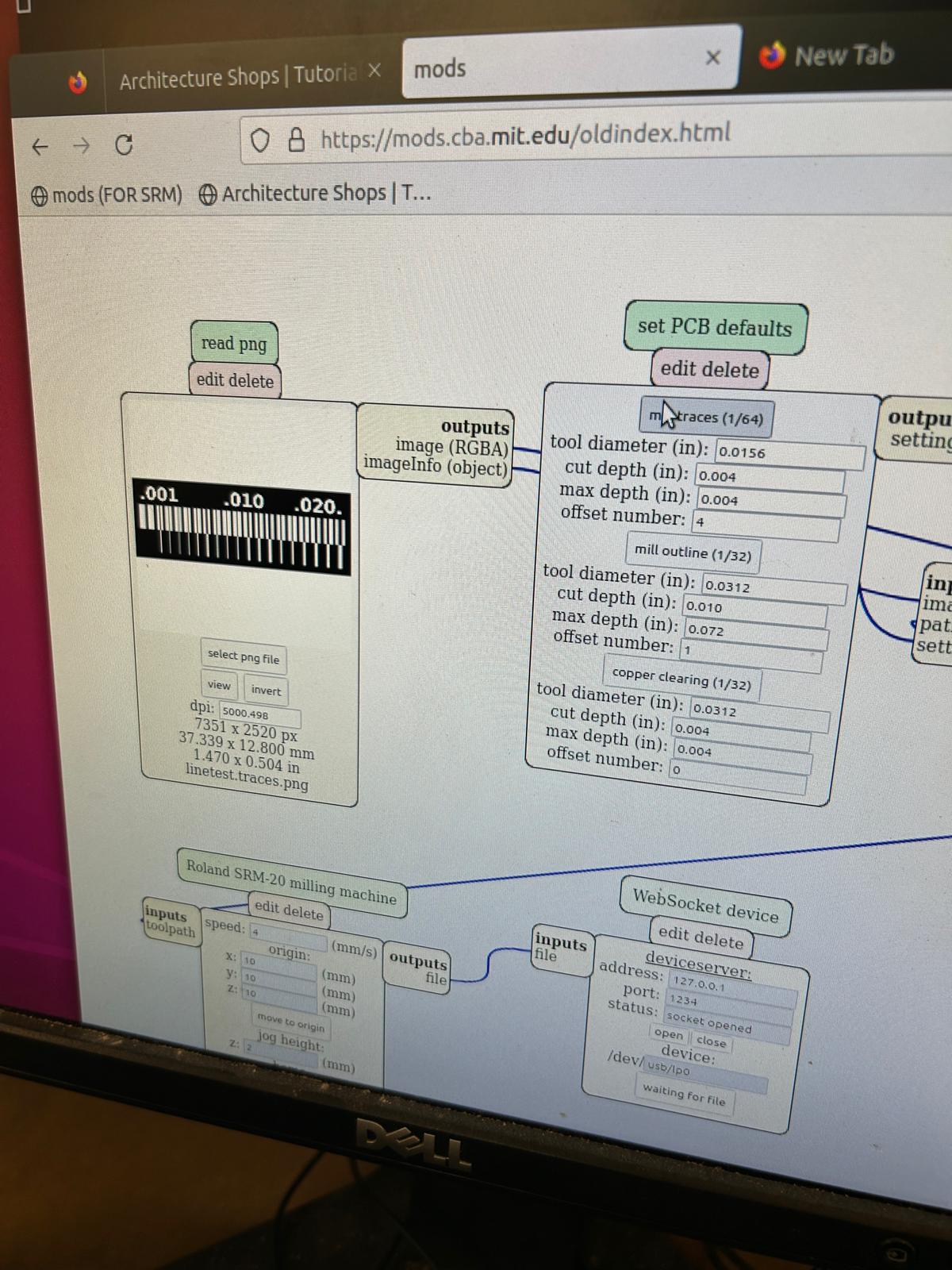
to start out with, it is important to remember that a normal milling job requires at least two different tool paths, one
for the milling of the copper layer (where we use a 1/64" bit), and another for the "cutting out" of the pcb, the milling
of the outline of our board (using a 1/32" bit), that will actually set it free from the rest of the material.
It is important to do remember that we should cut the circuit layer before the cut layer, to ensure that the material
we want to mill out of stays stable until the very end.
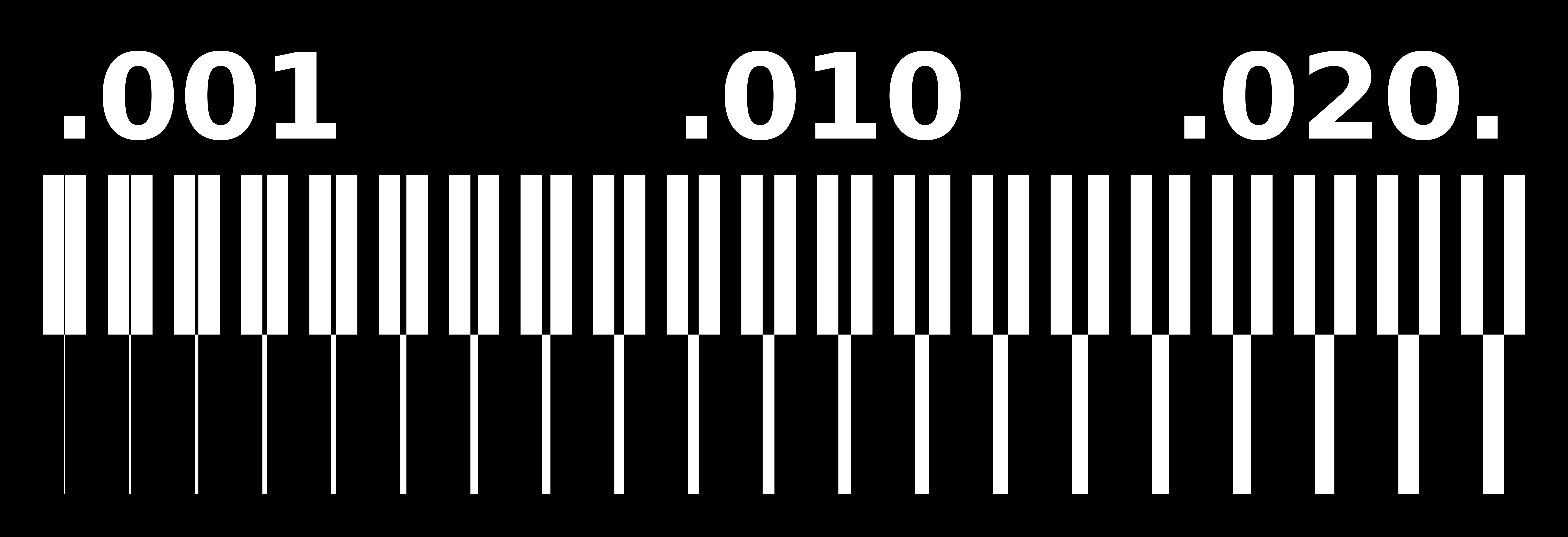
to get used to the machine and its milling tolerances, we started as a group milling the test strip that was shown
during class. the two different files are
containing the traces
and another one containing the outline
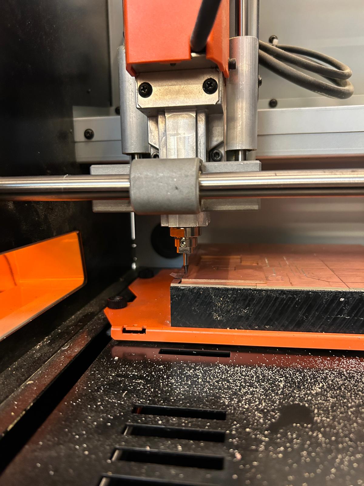
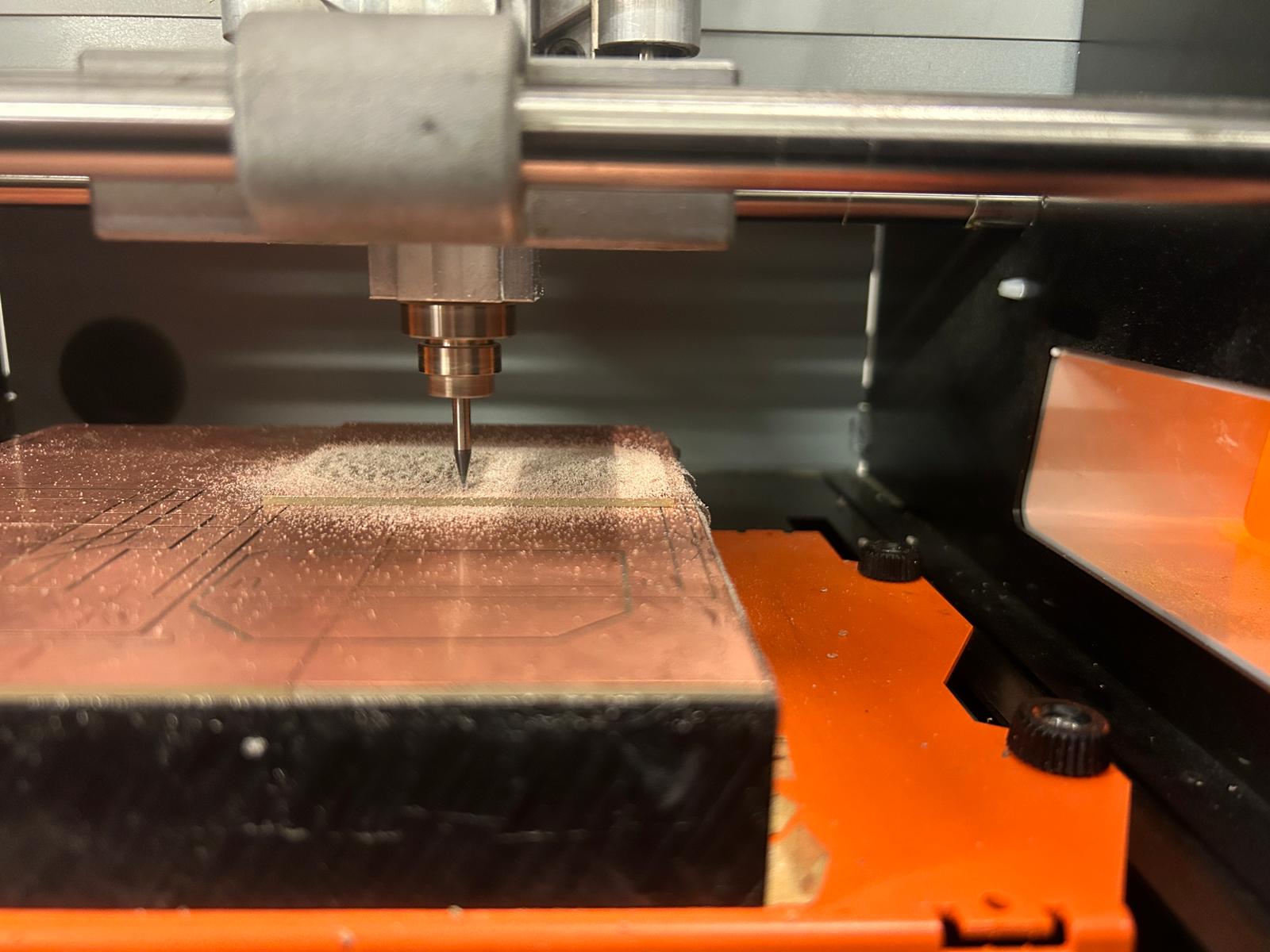
placing in the milling bit is pretty straight forward, one has to make sure to place it pretty far in when inserting it for the first time, and tighten it finger-tight. then one moves the drill bit via mods to a project-zero-point in the x and y coordinate, and moving carfully down with the z-value, until the bit is roughly 1/4" above the material we want to mill out of. at that point we will losen the set screw at the milling head again, WHILE HOLDING THE BIT, and slowly lower it to the copper plate. ones they are touching, we tighten the set screw again, and we have a set zero-location for both our traces and the cutout of our pcb.
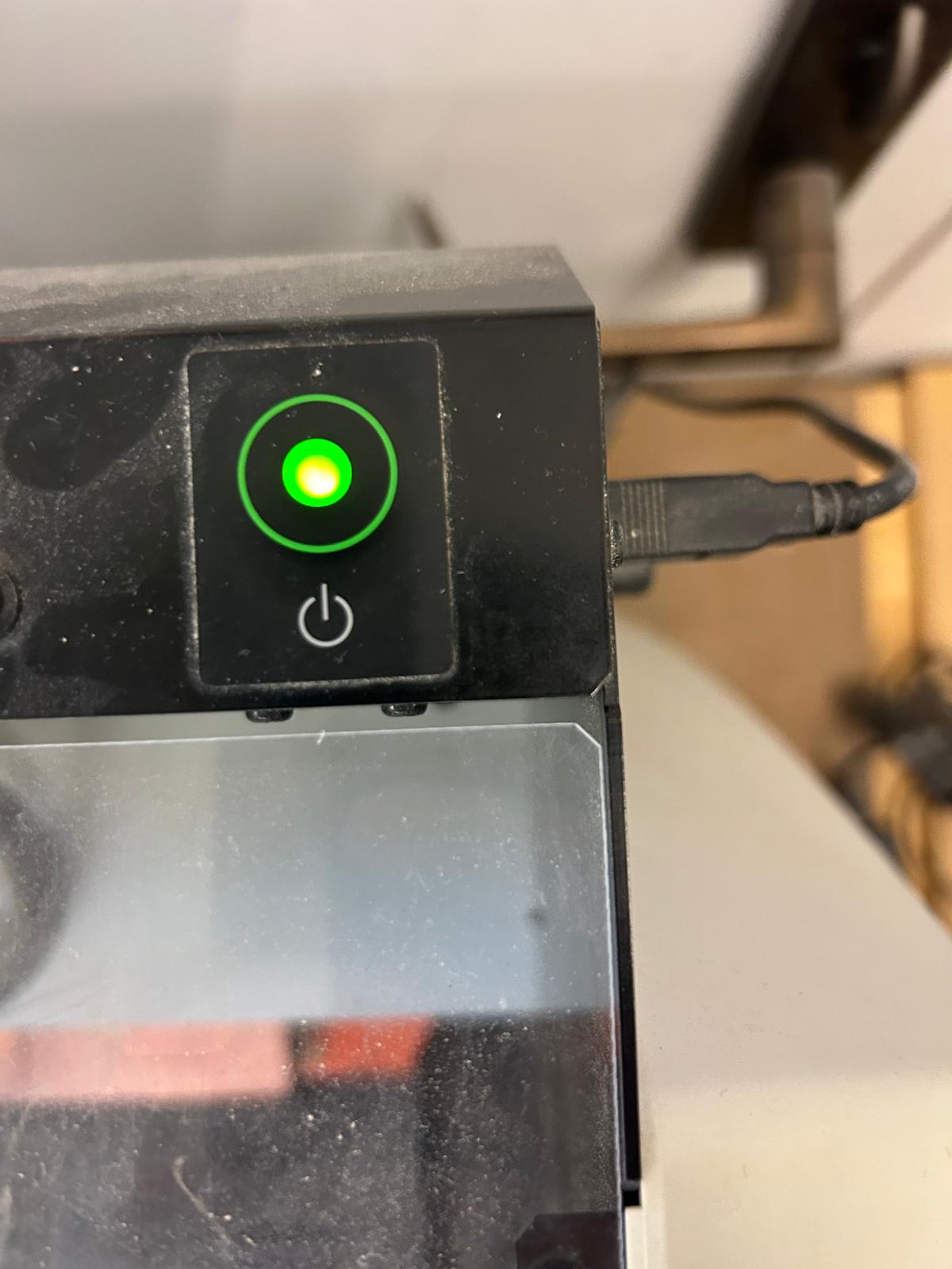
when opening and closing the screen at the modela SRM-20, it can happen that the lid sensor, checking that the lid is closed, can get confused, in which case the power button starts blinking. we have to shut the mill down and restart the machine, but since the project zero-location is set in mods, we can safely navigate back to the coordinateswe have set.
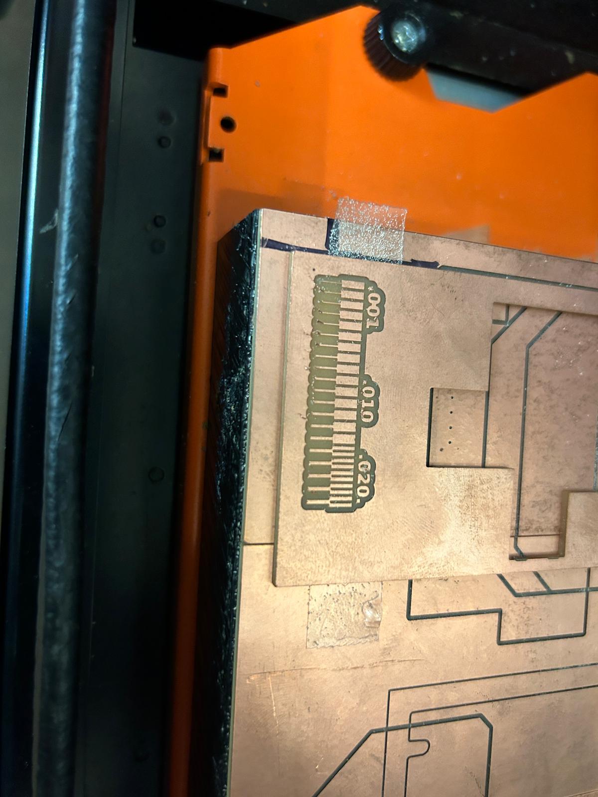
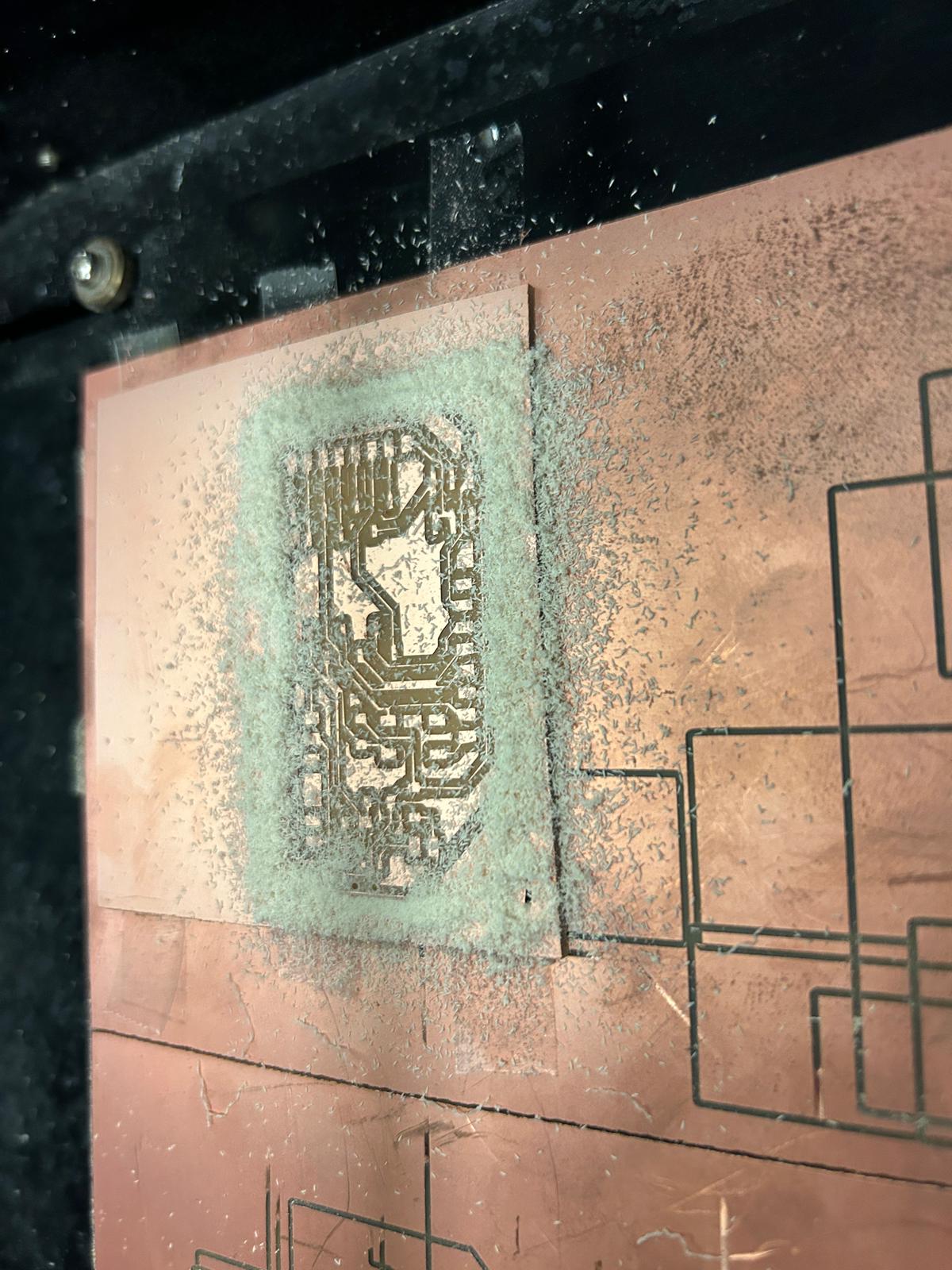
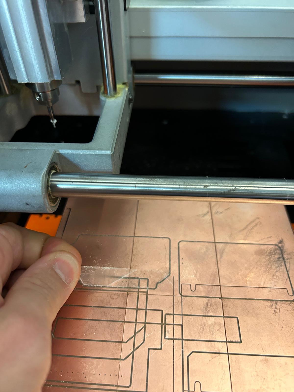
here we see the result after the 1/64" bit trace milling job (after we vacuumed)...
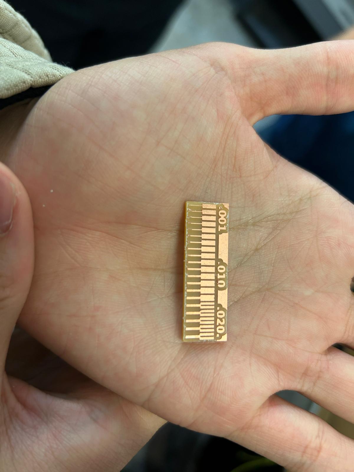
...and here is the finished result after the 1/32" cutting job. we can clearly see which traces start to peel of.
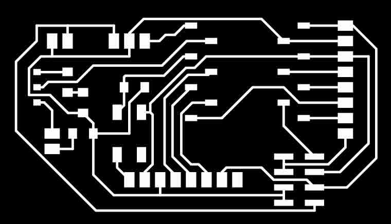

getting my own designed pcb ready to be printed involved looking (to the best of my ability) again through my design parameters in Kicad, and making sure that the tolerances i work with are in line with the milling resolution we observerd in the test piece. i exported the kicad file as a svg, opened it in illustrator and saved it at a .png file (with 300 dpi). IMPORTANT point: make sure that the 'artboard' in illustrator is not letter size or unreasonably large, since the project zero-location we have to set up before milling in mods referres to the very bottom left corner of the .png file, regardless if it contains your traces or just blank space.
my first try was to with the older milling machine - the modela MDX-20. while setting it up was the same process as for the other machine. i did have an issue for a while, where mods was not finding the USB port through which this mill was connected, but the arch shop website has in their pcb tutorial page a way to open the terminal and prompt the USB terminal permissions to be reset. NOTE - THIS WILL REQUIRE YOU TO KNOW THE COMPUTER'S PASSWORD. type:
sudo chmod a+rwx /dev/ttyUSB0
once this is done, one should see the usb permission granted in the mods.
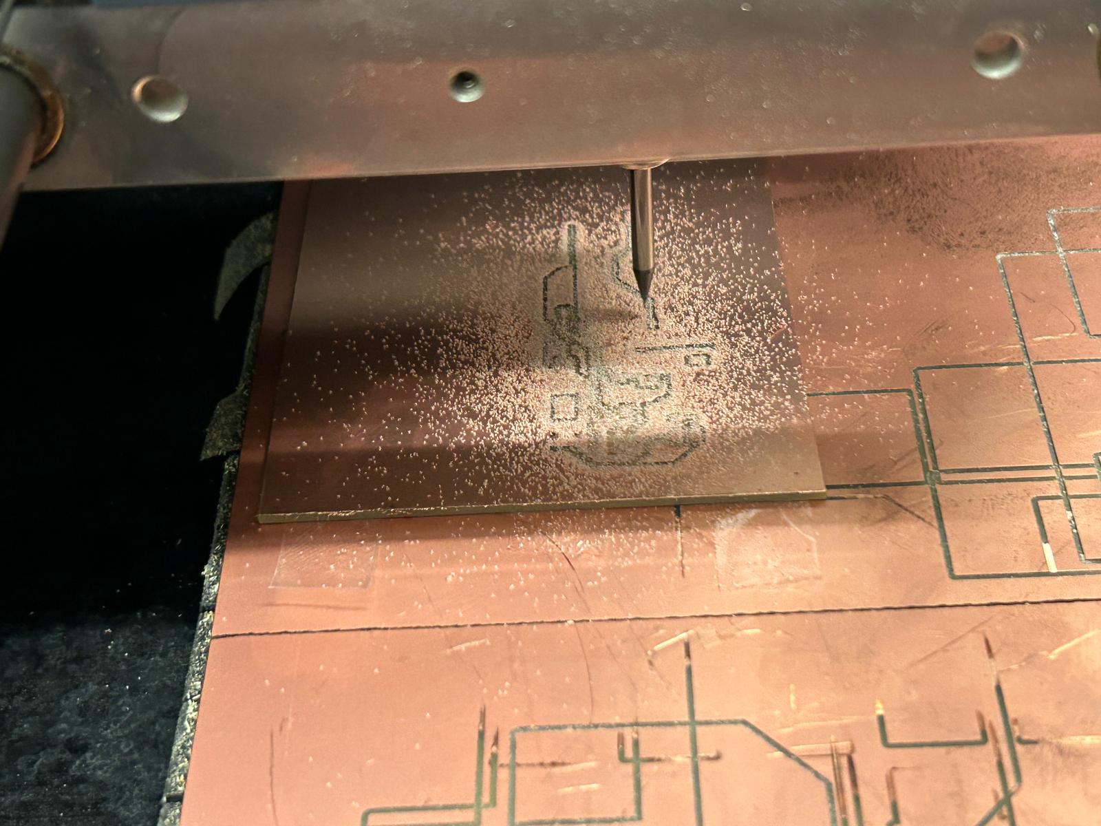
the milling job required a little more nerves, since one feels very unprotected during the milling job.
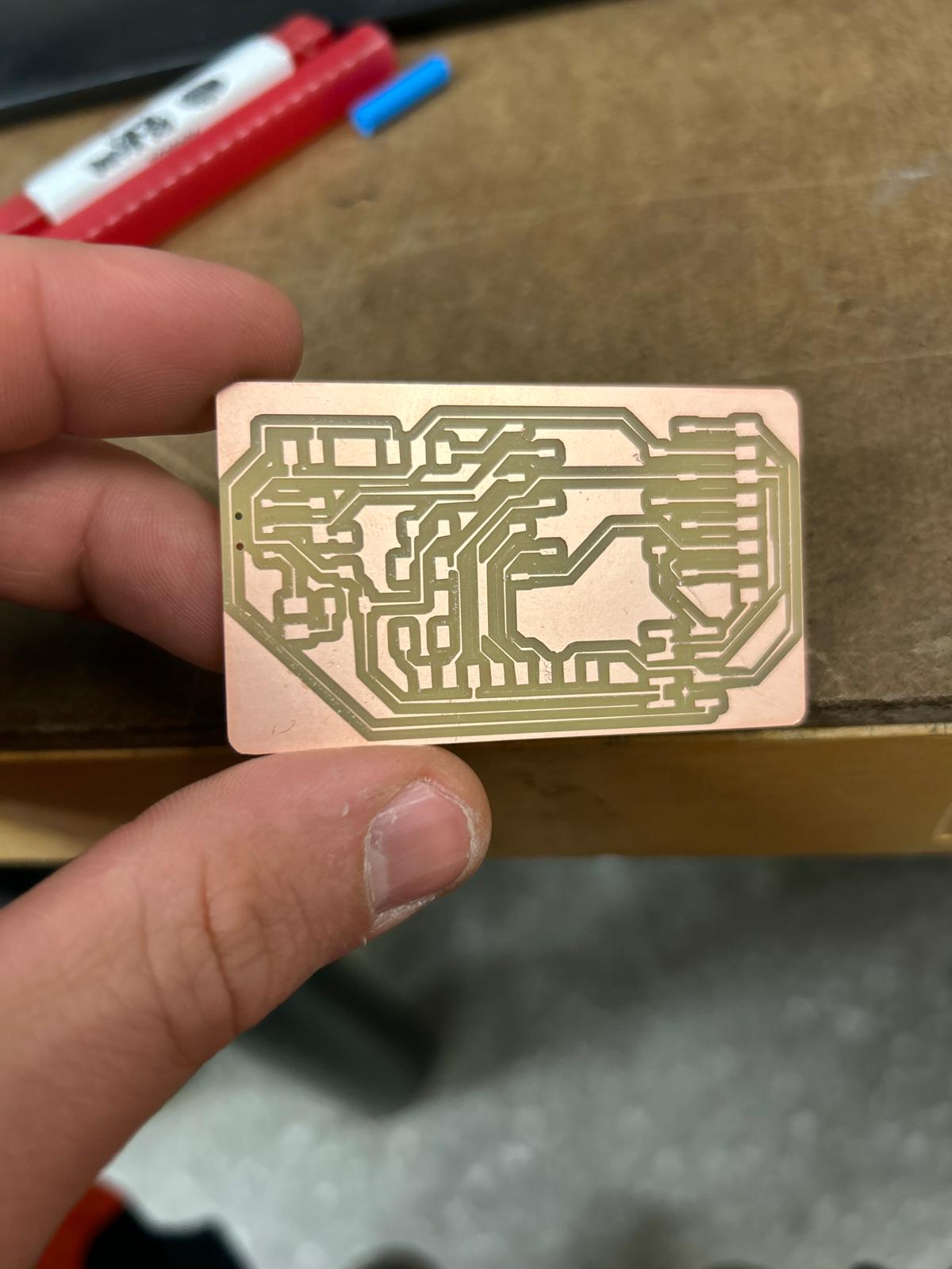
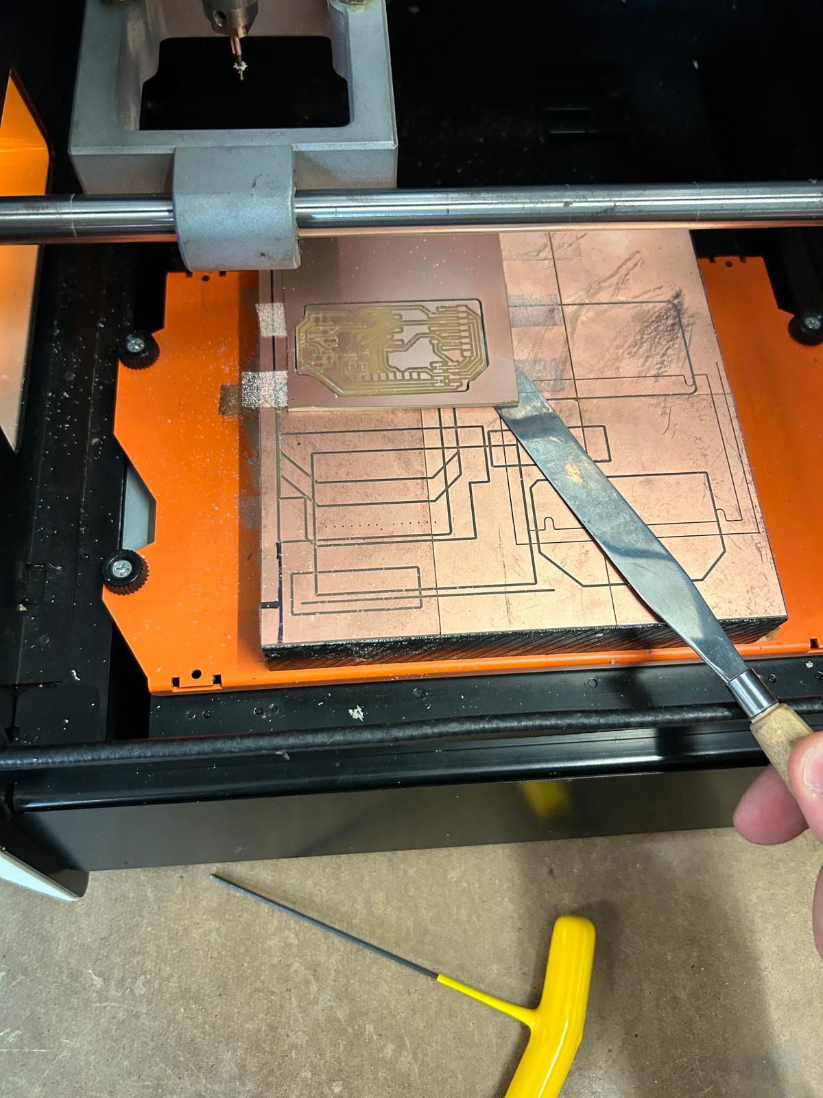
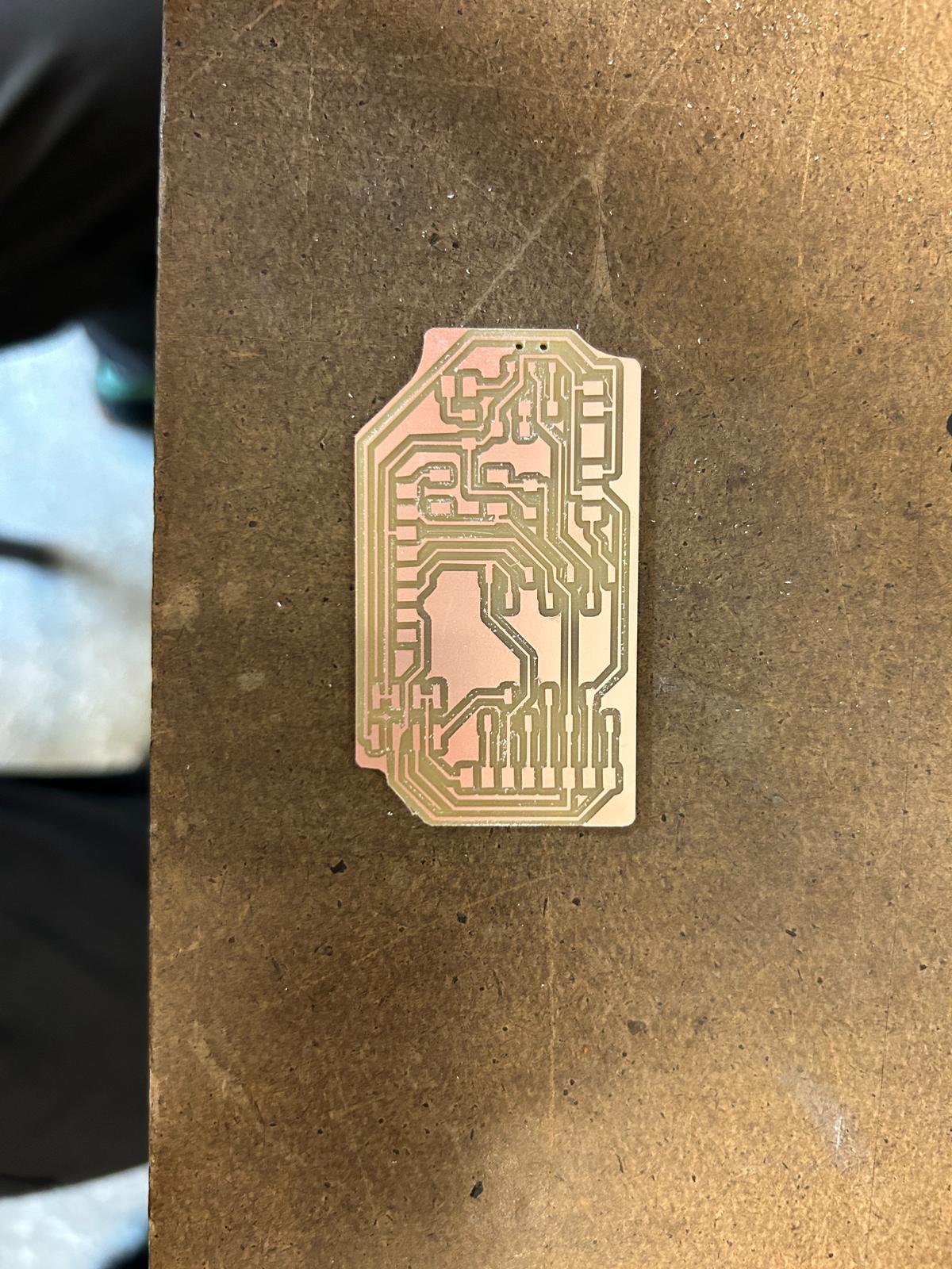
and this is how it came out. i am not sure what the issue with this milling job was, but it was at first glance a little disappointing to see the different thickness of traces throughout my board. a double checked all the trace thicknesses in Kicad and in the .png file i used, but in both cases they were actually correct. so the issue must have been that somehow the mill was not calibrated/running smoothly.
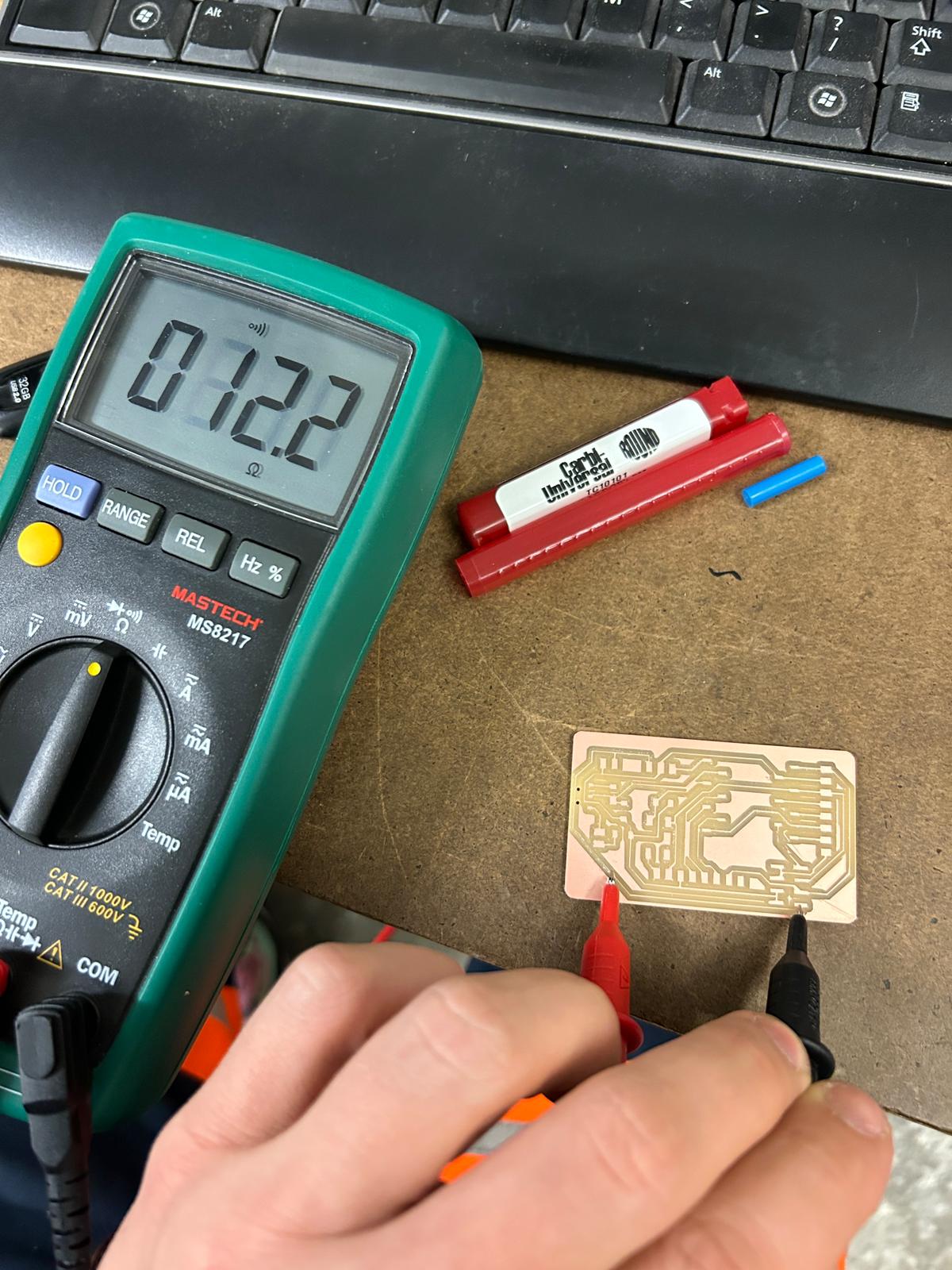
to make a quick initial test to see whether the traces actually connect, and whether I would be able to use
this pcb, i decided to use the multimeter, to send a small current through its terminals. i set the multi-meter
function to the audio-signal, so i did not need to look at its display while holding the terminals stable on the
tiny traces of the pcb, but could simply listen for the beep, or get worried (more often then not) when i did not.
i realized very quickly that, not only did it not cut some traces so thin, that the actual copper broke off, but
in some other spaces
looking again at kicad, i madesure that the parts that failed in the previous print would come through if i mill again. so i corrected the thicknesses, changed the spacing and outline....and did it again (i did not document that there was actually another failed pcb milling job in between, where i missed that second trace is merged with another one, and i just was not able to separate them with a knife)
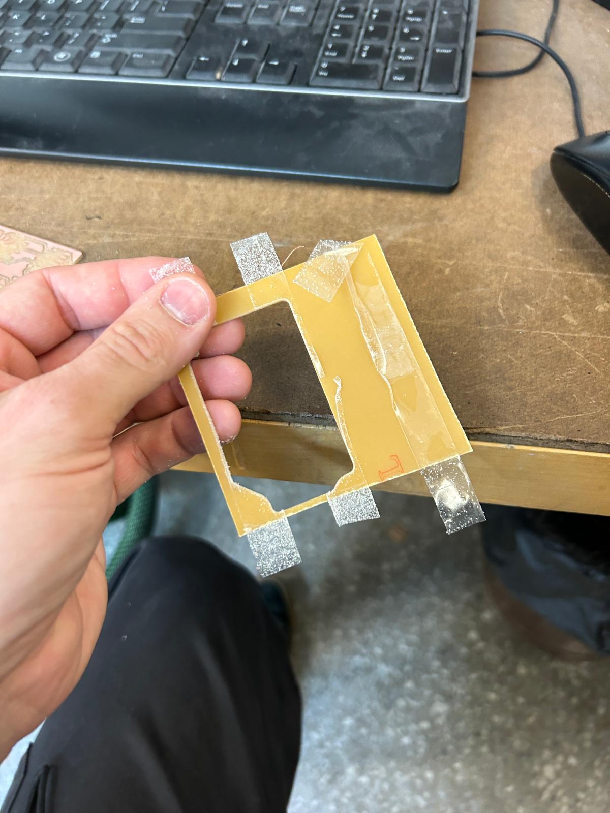
carerfully removing the milled pcb
removing all the nasty doublesided-tape from the spoil board...
...and from the left-over material, so someone else can use the rest.
YAY, it worked? i hope
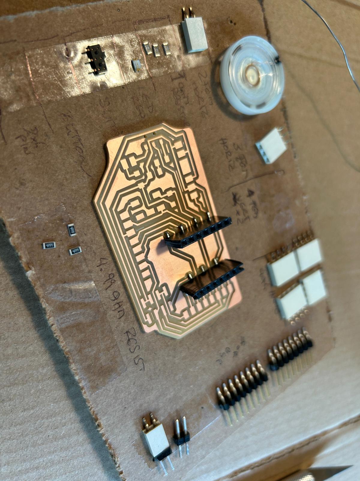
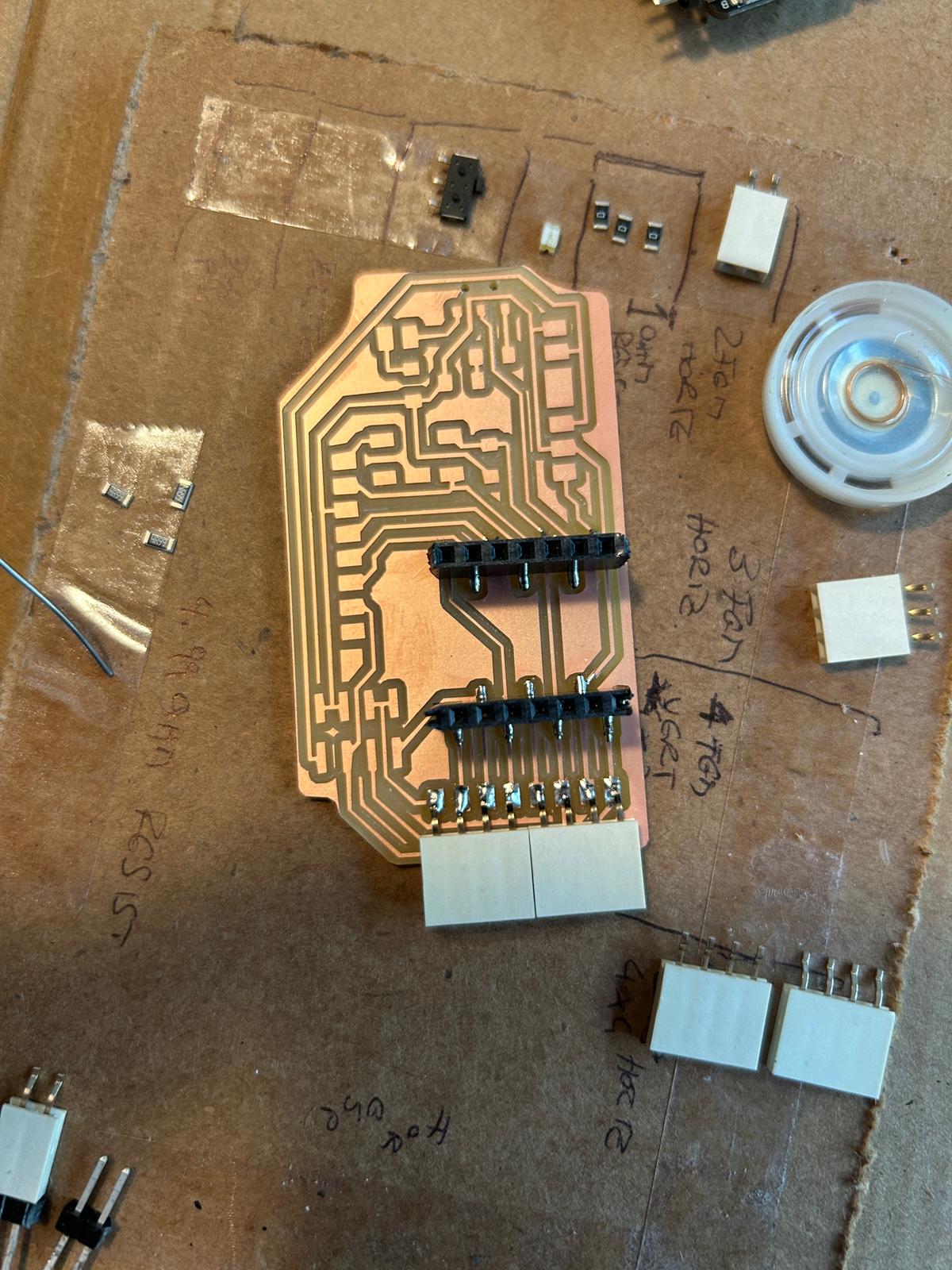
making sure we have all the components in the shop (which we didn't), or finding things that i could tweak/bend/cut into shape to do what i want it to do (in the future i might look at all the pieces in the shop before milling)
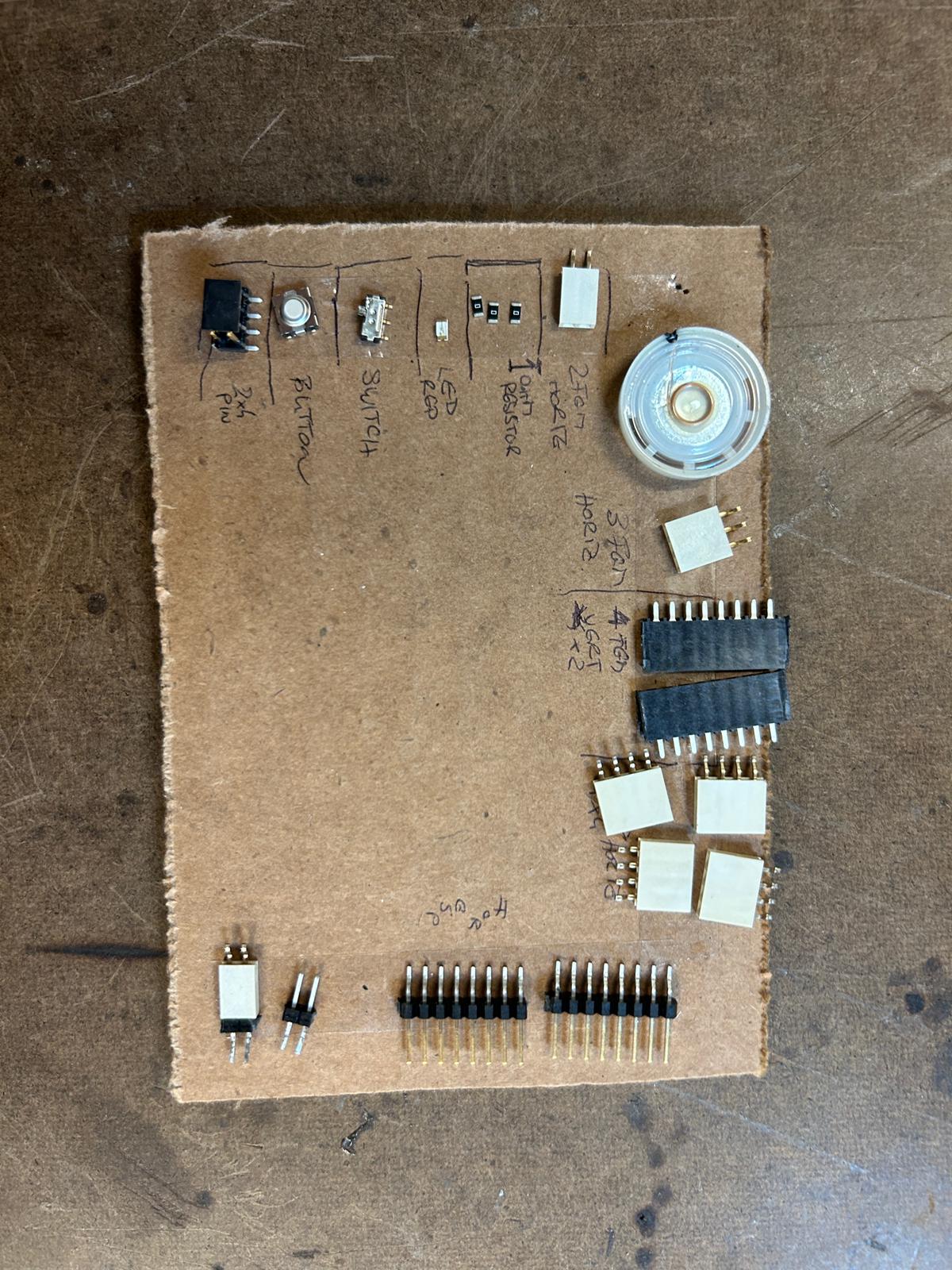
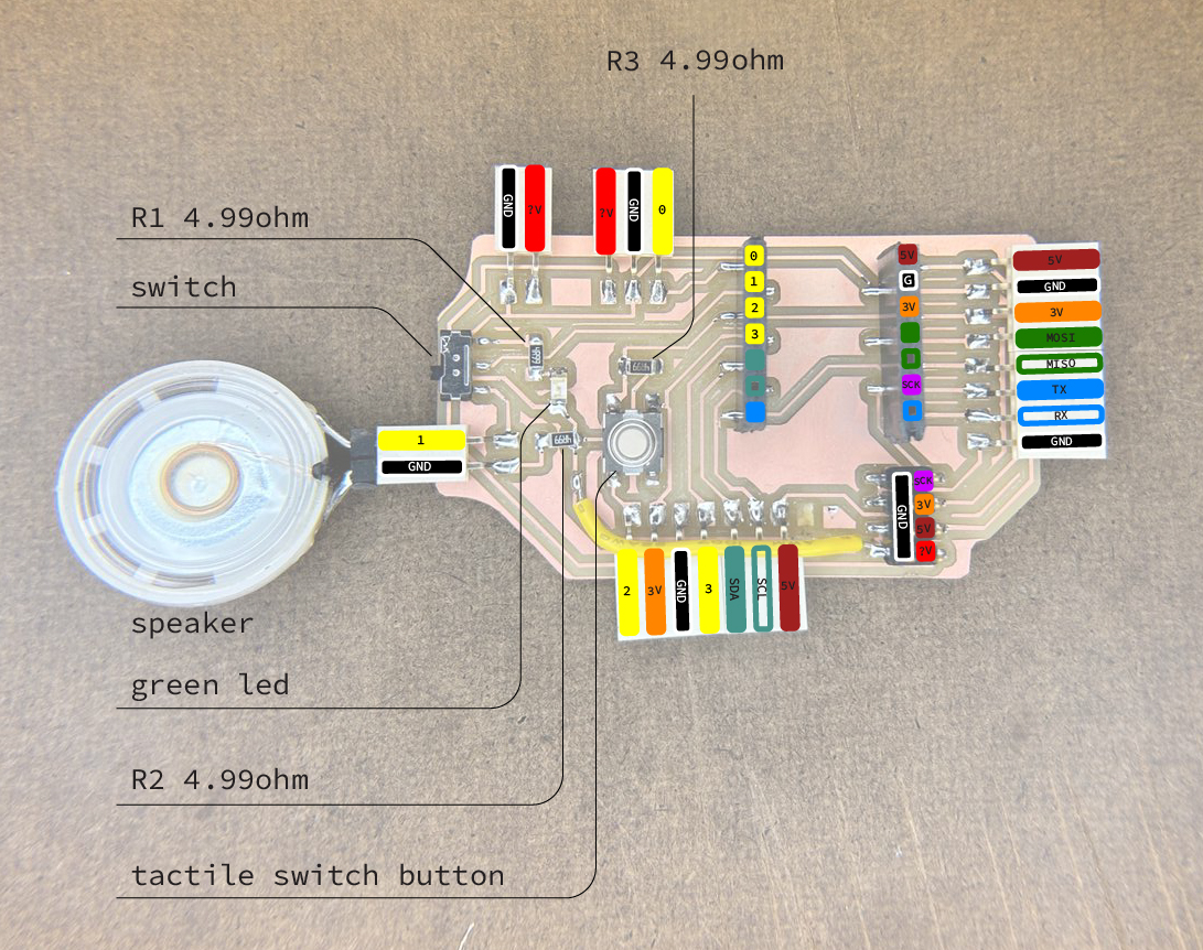
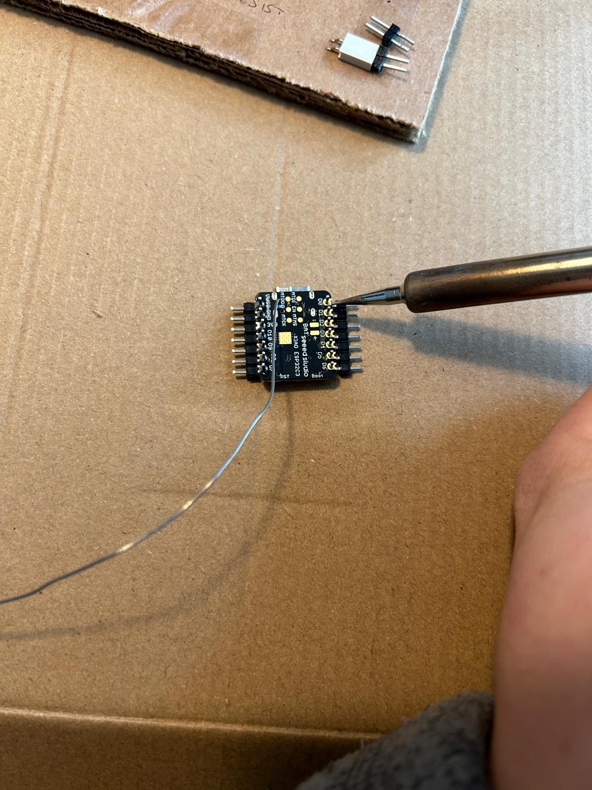
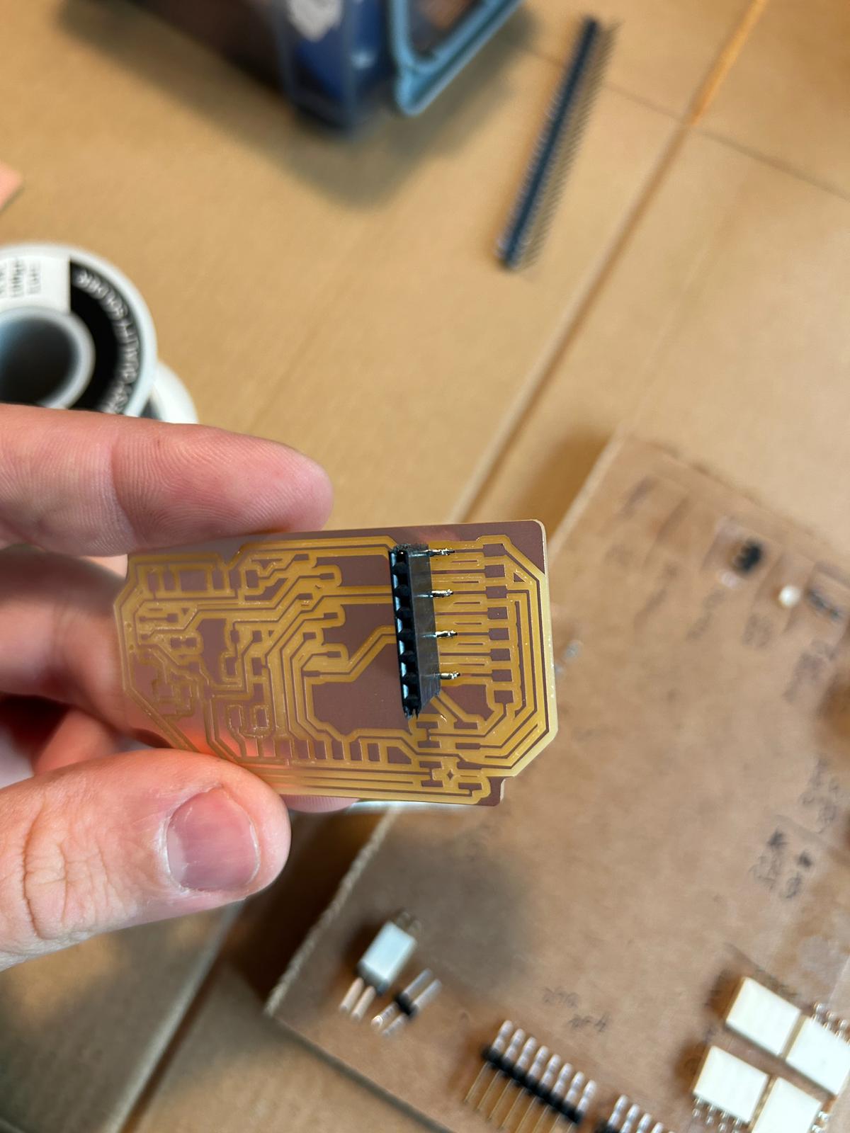
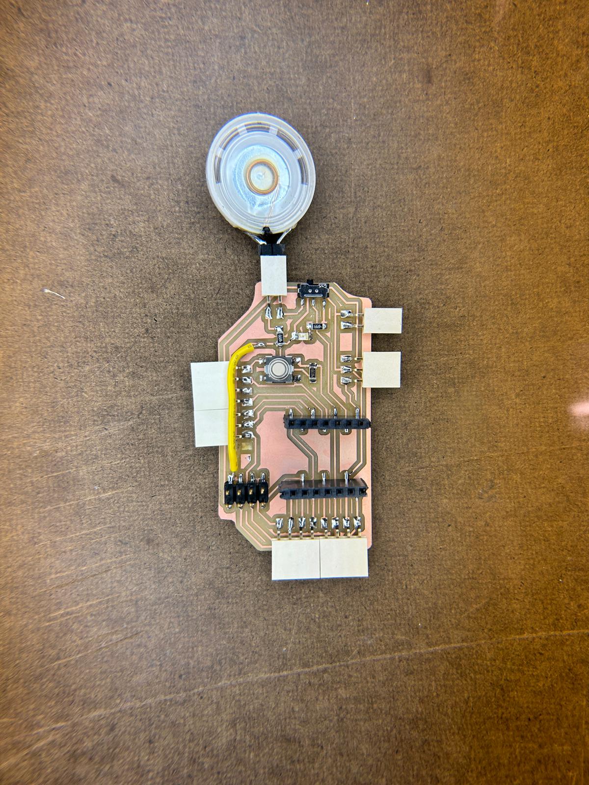
i did not want my esp-32c3 soldered permanently on my pcb, so i gave it some male connector pins, that would slot into vertical connectors on my pcb. using L-shaped ones would additionally allow me to double up all the pins from the microcontroller.
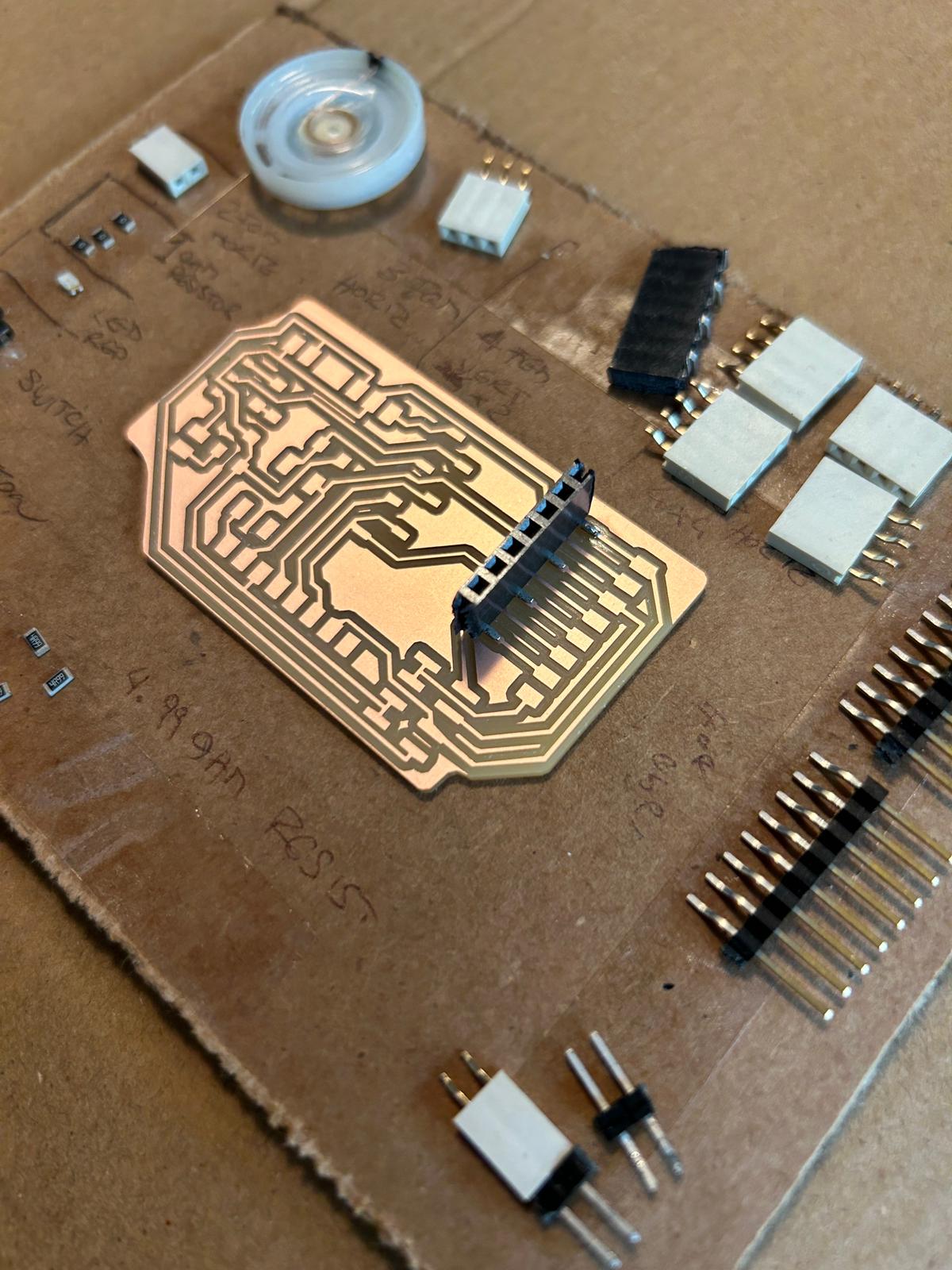
i took jenn's advice and started with the bulkiest objects in the center oft the board, and would work myself towards the outside, starting with the vertical connectors for the microcontroller to attach to. this piece did not exist in the shop in the way i used them, since every pin was supposed to be left or right, and bend horizontally, so i took vertical connectors and bend them with needle-nose pliers into place.
and thats how the first solder spots look
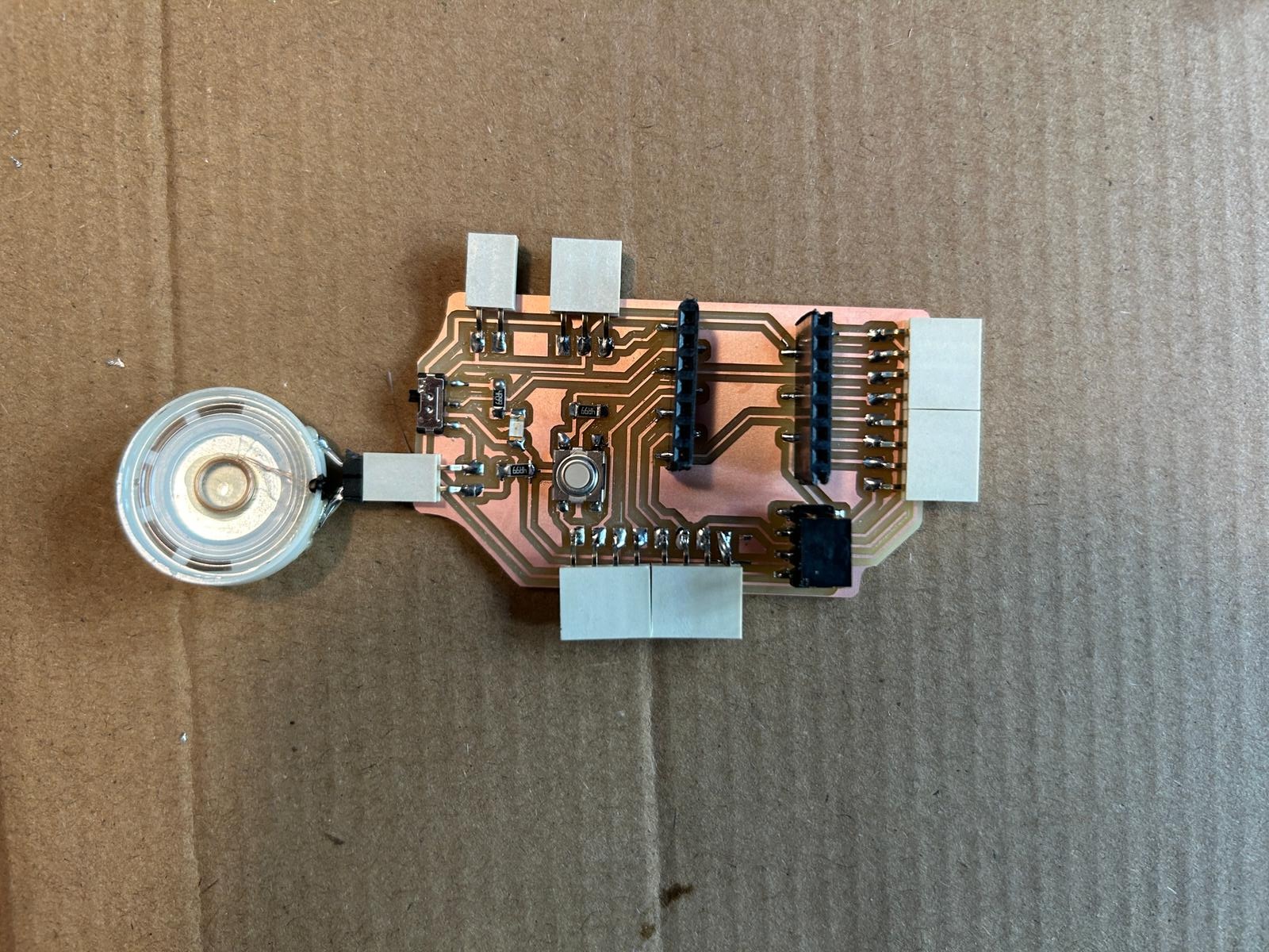
i moved on to the other connectors...
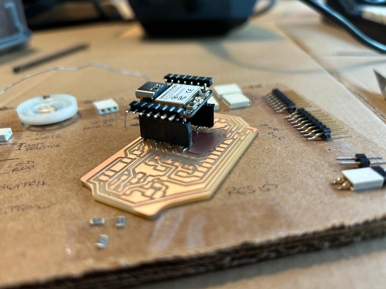
and tested if the esp-32c3 would be able to connect.
from that moment i repeated the same process for all the other parts... heat up the copper pad, lay down a solder drop, place the component on top, reheat the solder so the components pin would sink in, then solder all the other connections properly, and redo the first soldering spot a second time
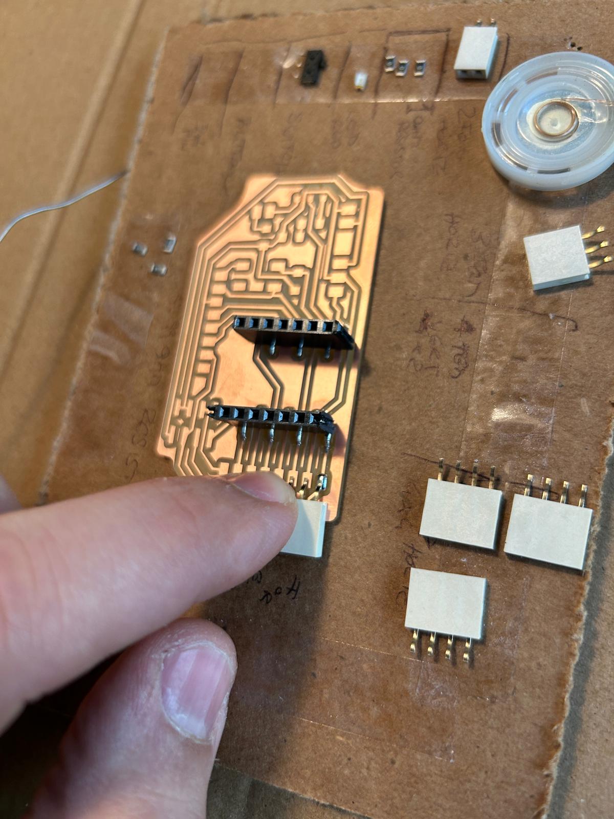
i had 8 connectors going into both directions, so i added 2x 4 pin connectors.
and after a few more spots, and a speaker, i felt i was done soldering.
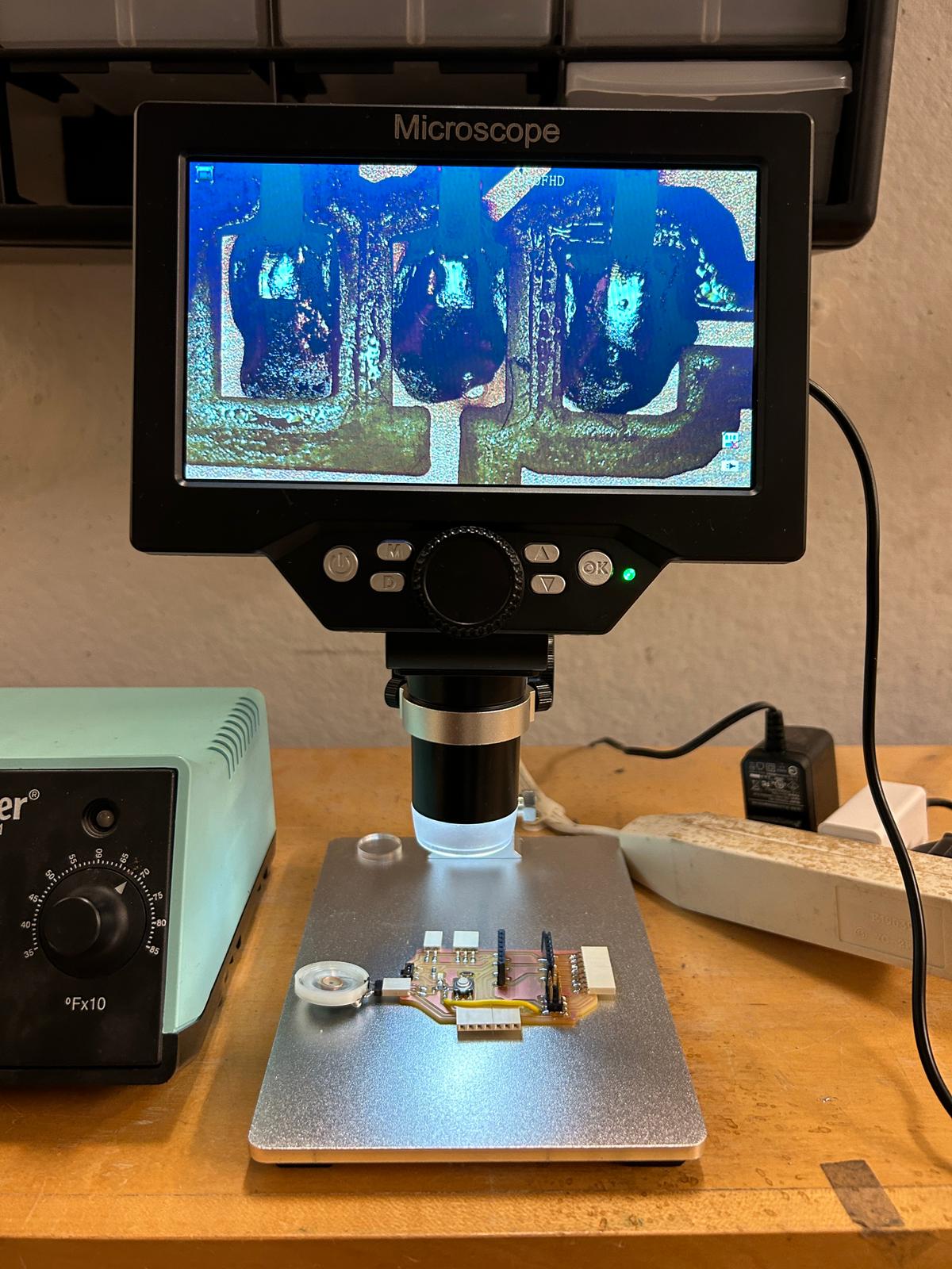
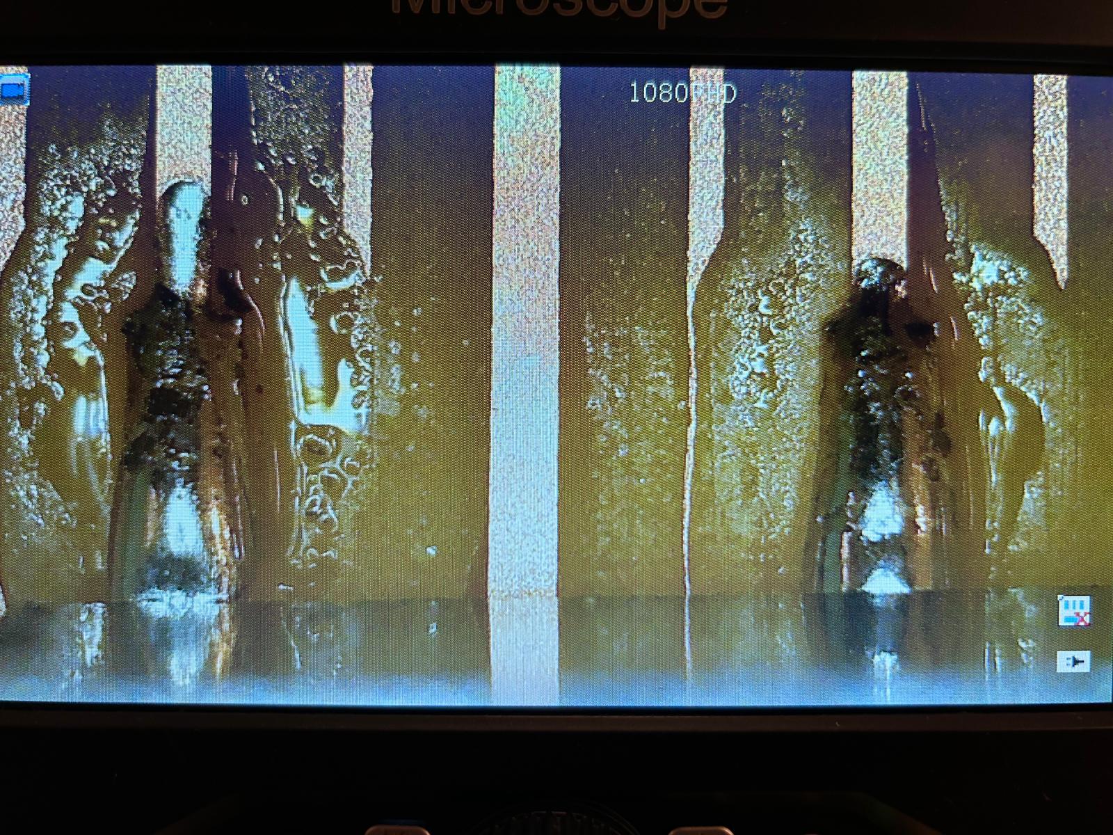
i used the microscope to check out if they look ok
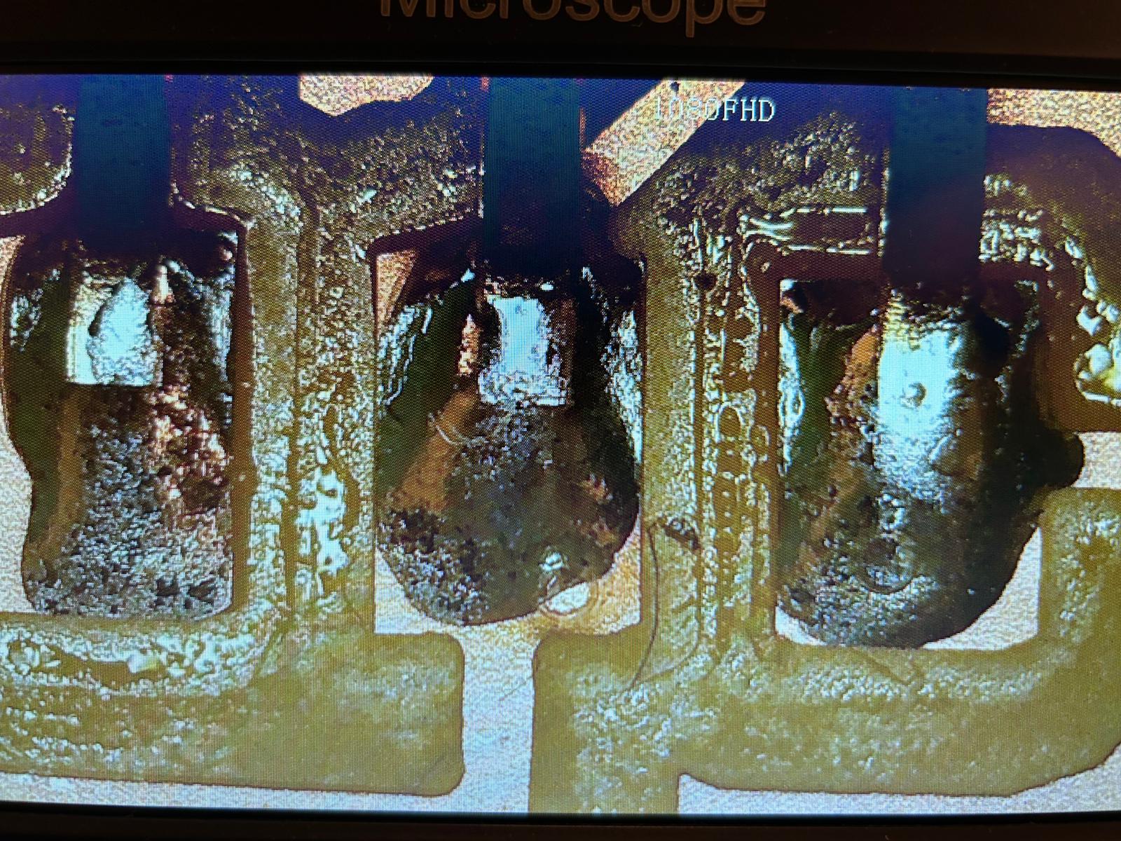
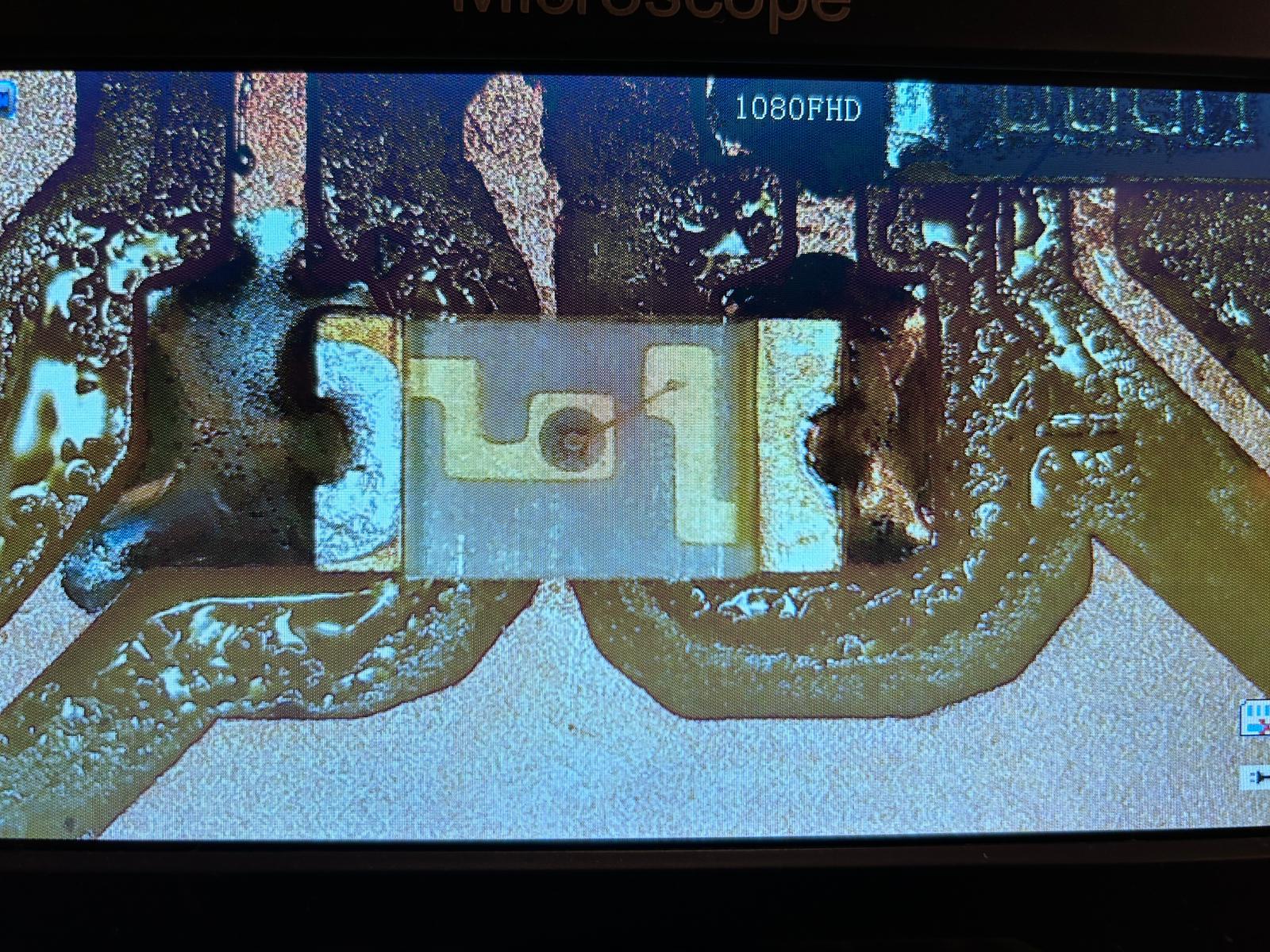
but then... i dropped it on the way to the shop...
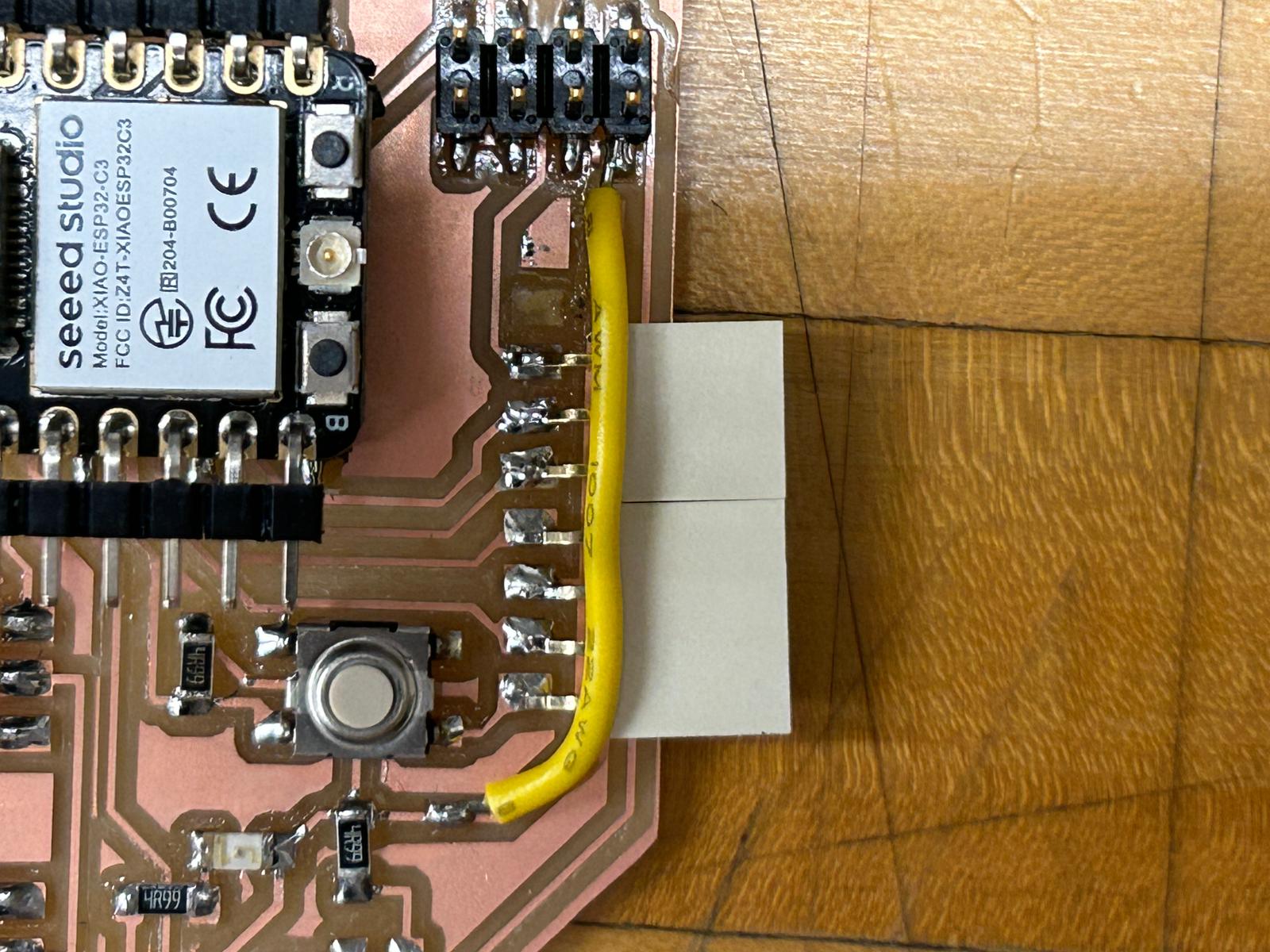
and it landed on one of the horizontal connectors, that came lose. the soldering spot was strong, too strong i would argue because it ripped off a copper trace that was connecting the ground to other components. so i reduced the ooriginal 4 pin connector to a 3 pin connector, and used a solid-core wire to make tight laying cable connecting the ground again. i like the look
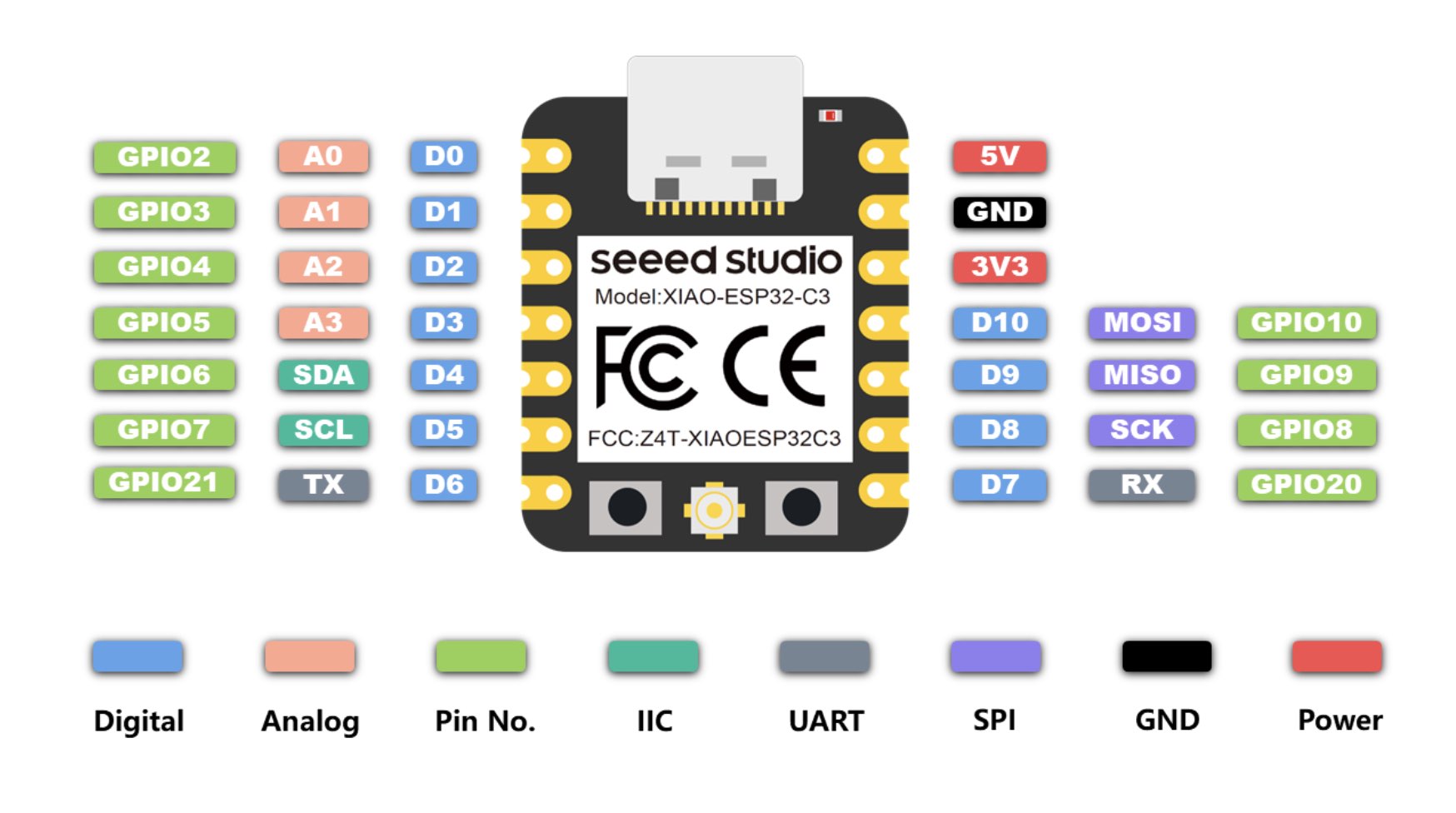
after all of this, it was already a little late, and i needed to find out how to run micropython on the esp32-c3 through
thonny (documentation will follow)
but this is what I ended up doing with it (for now! -- i have a lot of other ideas planned with it, mainly to understand
how i can communicate as many things as possible at once through it)
here is the python code i used:
                        import time
from machine import Pin, PWM

# notes in hz
NOTE_B0 = 31
NOTE_C1 = 33
NOTE_CS1 = 35
NOTE_D1 = 37
NOTE_DS1 = 39
NOTE_E1 = 41
NOTE_F1 = 44
NOTE_FS1 = 46
NOTE_G1 = 49
NOTE_GS1 = 52
NOTE_A1 = 55
NOTE_AS1 = 58
NOTE_B1 = 62
NOTE_C2 = 65
NOTE_CS2 = 69
NOTE_D2 = 73
NOTE_DS2 = 78
NOTE_E2 = 82
NOTE_F2 = 87
NOTE_FS2 = 93
NOTE_G2 = 98
NOTE_GS2 = 104
NOTE_A2 = 110
NOTE_AS2 = 117
NOTE_B2 = 123
NOTE_C3 = 131
NOTE_CS3 = 139
NOTE_D3 = 147
NOTE_DS3 = 156
NOTE_E3 = 165
NOTE_F3 = 175
NOTE_FS3 = 185
NOTE_G3 = 196
NOTE_GS3 = 208
NOTE_A3 = 220
NOTE_AS3 = 233
NOTE_B3 = 247
NOTE_C4 = 262
NOTE_CS4 = 277
NOTE_D4 = 294
NOTE_DS4 = 311
NOTE_E4 = 330
NOTE_F4 = 349
NOTE_FS4 = 370
NOTE_G4 = 392
NOTE_GS4 = 415
NOTE_A4 = 440
NOTE_AS4 = 466
NOTE_B4 = 494
NOTE_C5 = 523
NOTE_CS5 = 554
NOTE_D5 = 587
NOTE_DS5 = 622
NOTE_E5 = 659
NOTE_F5 = 698
NOTE_FS5 = 740
NOTE_G5 = 784
NOTE_GS5 = 831
NOTE_A5 = 880
NOTE_AS5 = 932
NOTE_B5 = 988
NOTE_C6 = 1047
NOTE_CS6 = 1109
NOTE_D6 = 1175
NOTE_DS6 = 1245
NOTE_E6 = 1319
NOTE_F6 = 1397
NOTE_FS6 = 1480
NOTE_G6 = 1568
NOTE_GS6 = 1661
NOTE_A6 = 1760
NOTE_AS6 = 1865
NOTE_B6 = 1976
NOTE_C7 = 2093
NOTE_CS7 = 2217
NOTE_D7 = 2349
NOTE_DS7 = 2489
NOTE_E7 = 2637
NOTE_F7 = 2794
NOTE_FS7 = 2960
NOTE_G7 = 3136
NOTE_GS7 = 3322
NOTE_A7 = 3520
NOTE_AS7 = 3729
NOTE_B7 = 3951
NOTE_C8 = 4186
NOTE_CS8 = 4435
NOTE_D8 = 4699
NOTE_DS8 = 4978

# has to be over 5hz, otherwise it fails
PAUSE = 5

# pin number for buzzer/led
buzzer_pin = Pin(3, Pin.OUT)

DEBUG = True

def play_melody(title, tune, tempo, buzz_pin):
    if DEBUG:
        print()
        print(title)
        print()

    for this_note in range(len(tune)):
        not_attached = tempo[this_note] < 1000
        note_tempo = tempo[this_note] if not_attached else tempo[this_note] - 1000

        if DEBUG:
            if this_note % 8 == 0:
                print()
            print(tune[this_note], note_tempo, "attached!" if not_attached else "", end=", ")

        # note duration
        note_duration = 2800 / note_tempo

        # play note
        pwm = PWM(buzz_pin, freq=tune[this_note], duty=512)  # duty 512 for 50% duty cycle
        time.sleep(note_duration / 1000.0)

        # stop tone playing
        pwm.deinit()

        # minimum time between notes
        pause_between_notes = note_duration * 1.30 if not_attached else note_duration
        time.sleep(pause_between_notes / 1000.0)

def main():
    imperial_march_tune = [
        # line 1
        NOTE_A4, NOTE_A4, NOTE_A4, NOTE_F4, NOTE_C5,
        NOTE_A4, NOTE_F4, NOTE_C5, NOTE_A4,
        NOTE_E5, NOTE_E5, NOTE_E5, NOTE_F5, NOTE_C5,
        NOTE_GS4, NOTE_F4, NOTE_C5, NOTE_A4,
        # line 2
        NOTE_A5, NOTE_A4, NOTE_A4, NOTE_A5, NOTE_GS5, NOTE_G5,
        NOTE_FS5, NOTE_F5, NOTE_FS5, PAUSE, NOTE_AS4, NOTE_DS5, NOTE_D5, NOTE_CS5,
        NOTE_C5, NOTE_B4, NOTE_C5, PAUSE, NOTE_F4, NOTE_GS4, NOTE_F4, NOTE_A4,
        NOTE_C5, NOTE_A4, NOTE_C5, NOTE_E5,
        # line 3
        NOTE_A5, NOTE_A4, NOTE_A4, NOTE_A5, NOTE_GS5, NOTE_G5,
        NOTE_FS5, NOTE_F5, NOTE_FS5, PAUSE, NOTE_AS4, NOTE_DS5, NOTE_D5, NOTE_CS5,
        NOTE_C5, NOTE_B4, NOTE_C5, PAUSE, NOTE_F4, NOTE_GS4, NOTE_F4, NOTE_C5,
        NOTE_A4, NOTE_F4, NOTE_C5, NOTE_A4,
        # line 4
        PAUSE,
        PAUSE,
        NOTE_A4, PAUSE, NOTE_A4, NOTE_A4, NOTE_A4, NOTE_A4, NOTE_A4, NOTE_A4, NOTE_A4, NOTE_A5, NOTE_A5, NOTE_A5, NOTE_A5,
        NOTE_E5, NOTE_E5, NOTE_E5, NOTE_E5, NOTE_F5, NOTE_F5, NOTE_F5, NOTE_G5, NOTE_A5, NOTE_A5, NOTE_A5, NOTE_A5, NOTE_AS5, NOTE_AS5, NOTE_AS5, NOTE_C6,

        # line 8
        PAUSE,
        NOTE_C5, NOTE_C4, PAUSE, NOTE_C4, NOTE_E5, NOTE_B4, NOTE_AS4,
        NOTE_A4, NOTE_GS4, NOTE_A4, PAUSE, NOTE_CS4, NOTE_FS4,
        NOTE_FS4, NOTE_FS4, PAUSE, NOTE_F4, NOTE_E4,
        NOTE_DS4, NOTE_D4, NOTE_DS4, PAUSE, NOTE_GS3, NOTE_B3,
        # line 9
        NOTE_B3, PAUSE, NOTE_GS3, NOTE_DS4,
        NOTE_C4, PAUSE, NOTE_GS3, NOTE_DS4, NOTE_C4,
        NOTE_C4, NOTE_C4, PAUSE,
        PAUSE,
        PAUSE,
        # line 1
        NOTE_A4, NOTE_A4, NOTE_A4, NOTE_F4, NOTE_C5,
        NOTE_A4, NOTE_F4, NOTE_C5, NOTE_A4,
        NOTE_E5, NOTE_E5, NOTE_E5, NOTE_F5, NOTE_C5,
        NOTE_GS4, NOTE_F4, NOTE_C5, NOTE_A4,
        # line 2
        NOTE_A5, NOTE_A4, NOTE_A4, NOTE_A5, NOTE_GS5, NOTE_G5,
        NOTE_FS5, NOTE_F5, NOTE_FS5, PAUSE, NOTE_AS4, NOTE_DS5, NOTE_D5, NOTE_CS5,
        NOTE_C5, NOTE_B4, NOTE_C5, PAUSE, NOTE_F4, NOTE_GS4, NOTE_F4, NOTE_A4,
        NOTE_C5, NOTE_A4, NOTE_C5, NOTE_E5,
        # line 3
        NOTE_A5, NOTE_A4, NOTE_A4, NOTE_A5, NOTE_GS5, NOTE_G5,
        NOTE_FS5, NOTE_F5, NOTE_FS5, PAUSE, NOTE_AS4, NOTE_DS5, NOTE_D5, NOTE_CS5,
        NOTE_C5, NOTE_B4, NOTE_C5, PAUSE, NOTE_F4, NOTE_GS4, NOTE_F4, NOTE_C5,
        NOTE_A4, NOTE_F4, NOTE_C5, NOTE_A4,

    ]

    imperial_march_tempo = [
    # line 1
    8, 8, 8, 12, 32,
    8, 12, 32, 4,
    8, 8, 8, 12, 32,
    8, 12, 32, 4,
    # line 2
    8, 12, 32, 8, 12, 32,
    32, 32, 16, 16, 16, 8, 12, 32,
    32, 32, 16, 16, 16, 8, 12, 32,
    8, 12, 32, 4,
    # line 3
    8, 12, 32, 8, 12, 32,
    32, 32, 16, 16, 16, 8, 12, 32,
    32, 32, 16, 16, 16, 8, 12, 32,
    8, 12, 32, 4,
    # line 4
    2,
    2,
    12, 32, 16, 48, 48, 48, 16, 48, 48, 48, 48, 48, 48, 16,
    16, 48, 48, 48, 48, 48, 48, 16, 16, 48, 48, 48, 48, 48, 48, 16,


    # line 8
    2,
    8, 32, 16, 32, 8, 12, 32,
    32, 32, 16, 16, 16, 2004,
    2004, 2016, 16, 12, 32,
    32, 32, 16, 16, 16, 2004,
    # line 9
    2006, 16, 8, 8,
    12, 32, 16, 32, 2008,
    2006, 2003, 2016, 16,
    2,
    2,
    # line 1
    8, 8, 8, 12, 32,
    8, 12, 32, 4,
    8, 8, 8, 12, 32,
    8, 12, 32, 4,
    # line 2
    8, 12, 32, 8, 12, 32,
    32, 32, 16, 16, 16, 8, 12, 32,
    32, 32, 16, 16, 16, 8, 12, 32,
    8, 12, 32, 4,
    # line 3
    8, 12, 32, 8, 12, 32,
    32, 32, 16, 16, 16, 8, 12, 32,
    32, 32, 16, 16, 16, 8, 12, 32,
    8, 12, 32, 4,

    ]

    play_melody("Imperial March", imperial_march_tune, imperial_march_tempo, buzzer_pin)

if __name__ == "__main__":
    main()
this code was written in python, based on the hz and durations i found in arduino exmple by netusco