#3 D headache
lookiong into 3d scanning, i experimented a little with a phone application, called Polycam, which uses photogrammetry, my initial goal was to scan a number of different electric and service boxes mounted to mit buildings. this is tool is normally NOT for free. i heard other people sign up for a free trial for this assignment, but i was lucky to have a friend who payed for polycam, and apparently one can sign in to multiple devices with the same credentials (pssssst...)
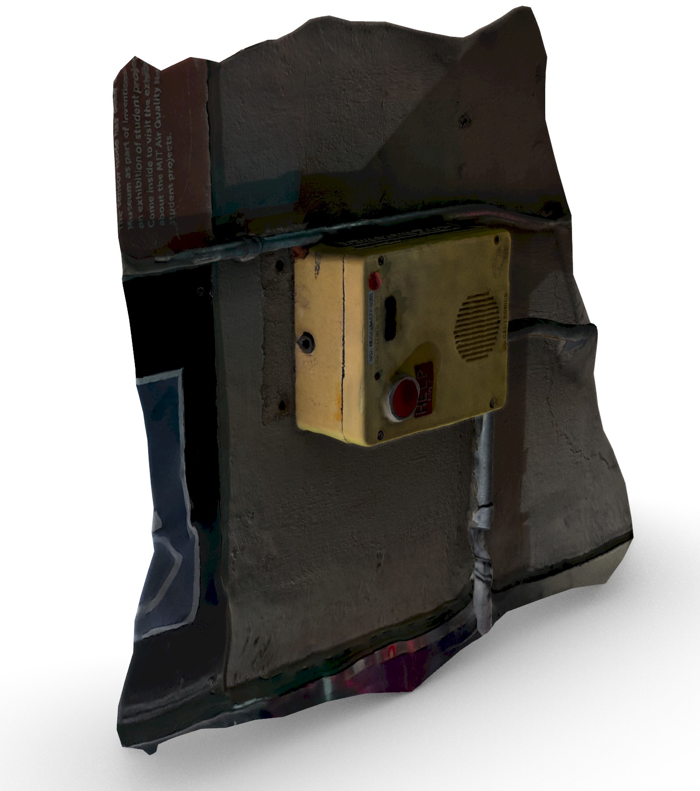
this is the output of polycam, the appearance is good, but that might be because the diffusion/color map is helping the appearance of the geometry a lot. since this has no way to measure actual distance, the model is most likely not very clean or accurate.but for a scan with only 27 images, this is actually really impressive. it took a few minutes to upload images to the cloud, where the 3d file is getting generated, before you see it in your projects and are able to download a .zip file with the 3d and mapping files.
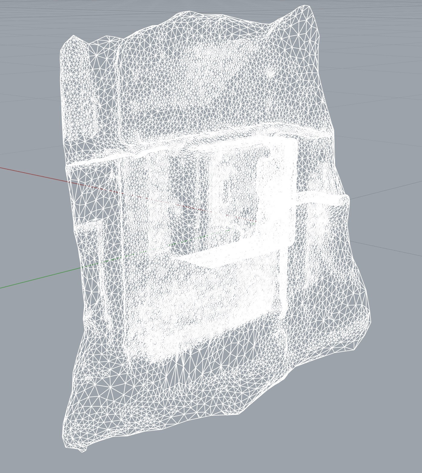
importing the 3d file into rhino,we are able to see the triangulated mesh that polycam made. it clearly defines areas with more details, creating a denser mesh, but edges that would in real life be straingt are constrained to the density of the mesh triangulation, and do not deliver a measurable or overly accurate output
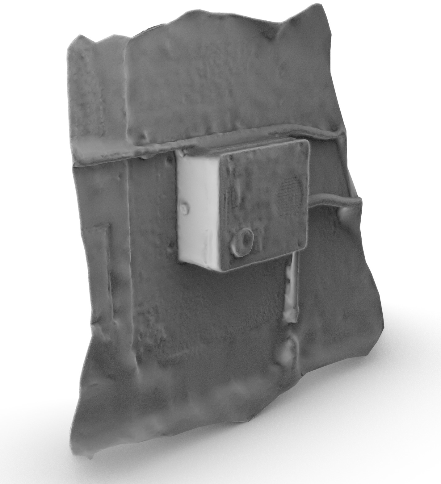
beside a nice mesh object, that took only 27 images and was generated by their servers, I was also getting the color/bump map of the scan, which is distributed in an interesting way. the rendered mesh shows where the inaccuracies emerged due to my image making, that does not adequatly cover all the details. it is impressive how the speaker of this box is rendered, while other objects like ducts and pipes end up blurred and inaccurate.
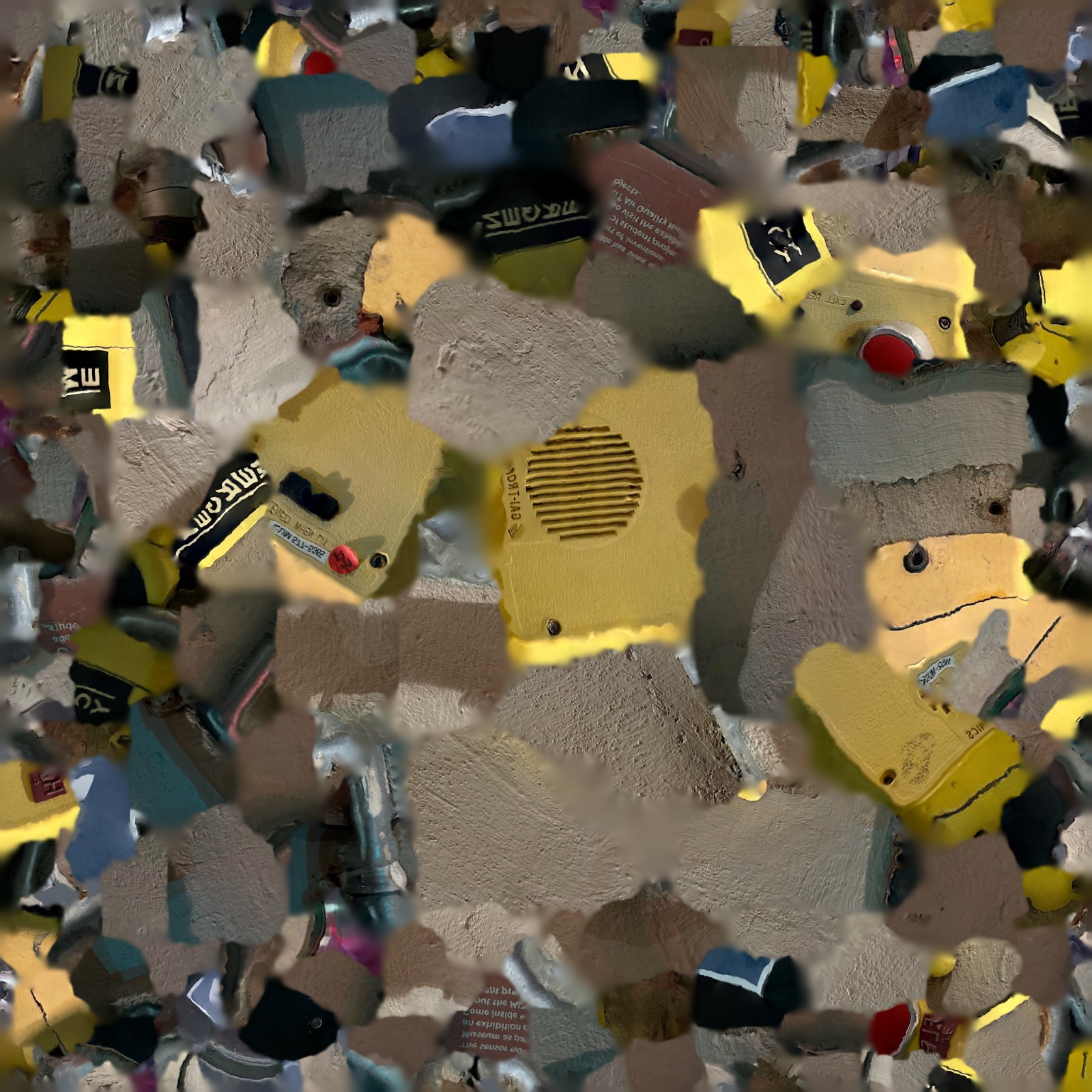
this was the diffusion map that polycam gave me with the mesh. while the mesh makes sense, this diffusion map maps it
impossible to track colors and elements of the diffusion map with the actual scanned objects. one can see the yellow
pieces that belong to the emergency box itself, and one might be able to identify elements of it, but the large majority
of the diffusion map is not created in a way in which one could use or manipulate it manually.
at this point i had something on my mind, literally. I suffer from chronic migraines and had several sets of mri images
taken of my brain. they are 2d images, but since they are scanns, i thought it would be interesting to use it as a
starting point of this project and to trace the layers. so i started the weird task of model my own brain
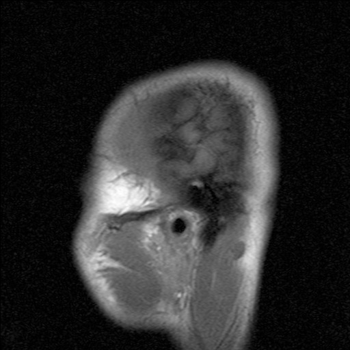
the slices of the mri images have been take approximately every 5mm, one set slicing my head vertically the other horizontally. here are some of the images i used.
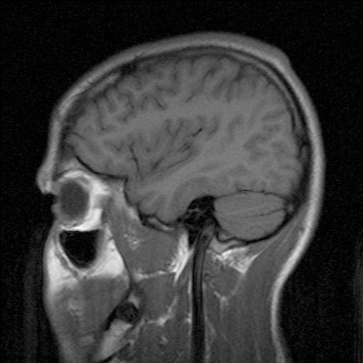
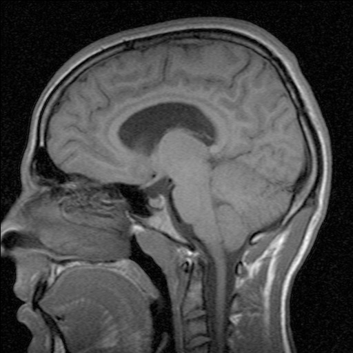
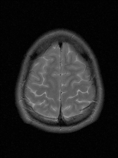
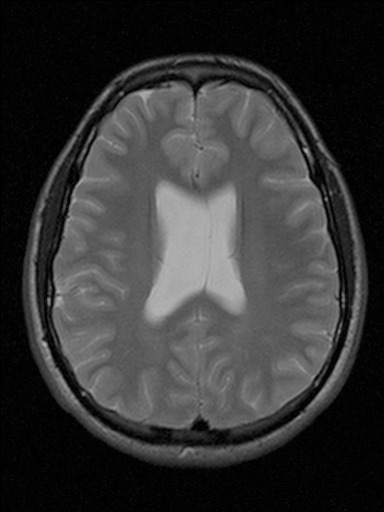
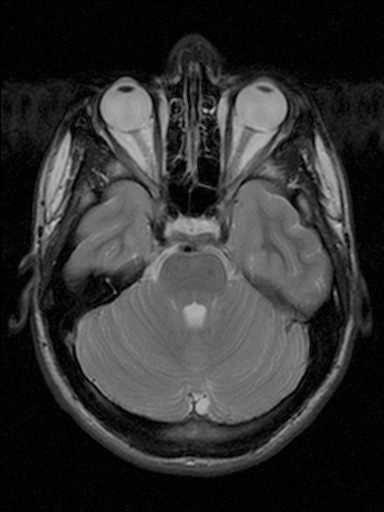
the last image is definitely my favorite scan, slicing through parts of my noes as well as eyeballs...
kinda creepy, kinda cool
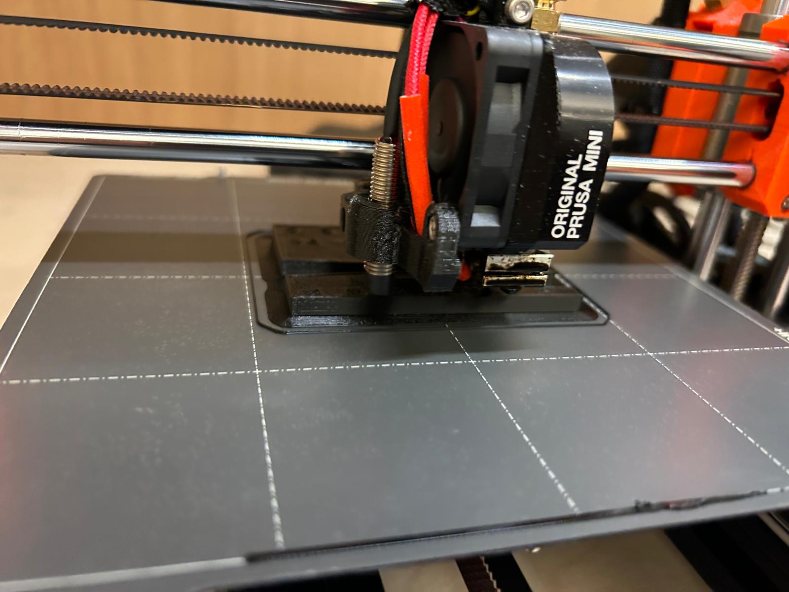
before starting with 3d printing something so large and complicated, i did some studies with the resolution,
overhang prints, sizing of gaps and walls, as well as cylindical points and sharp edges.
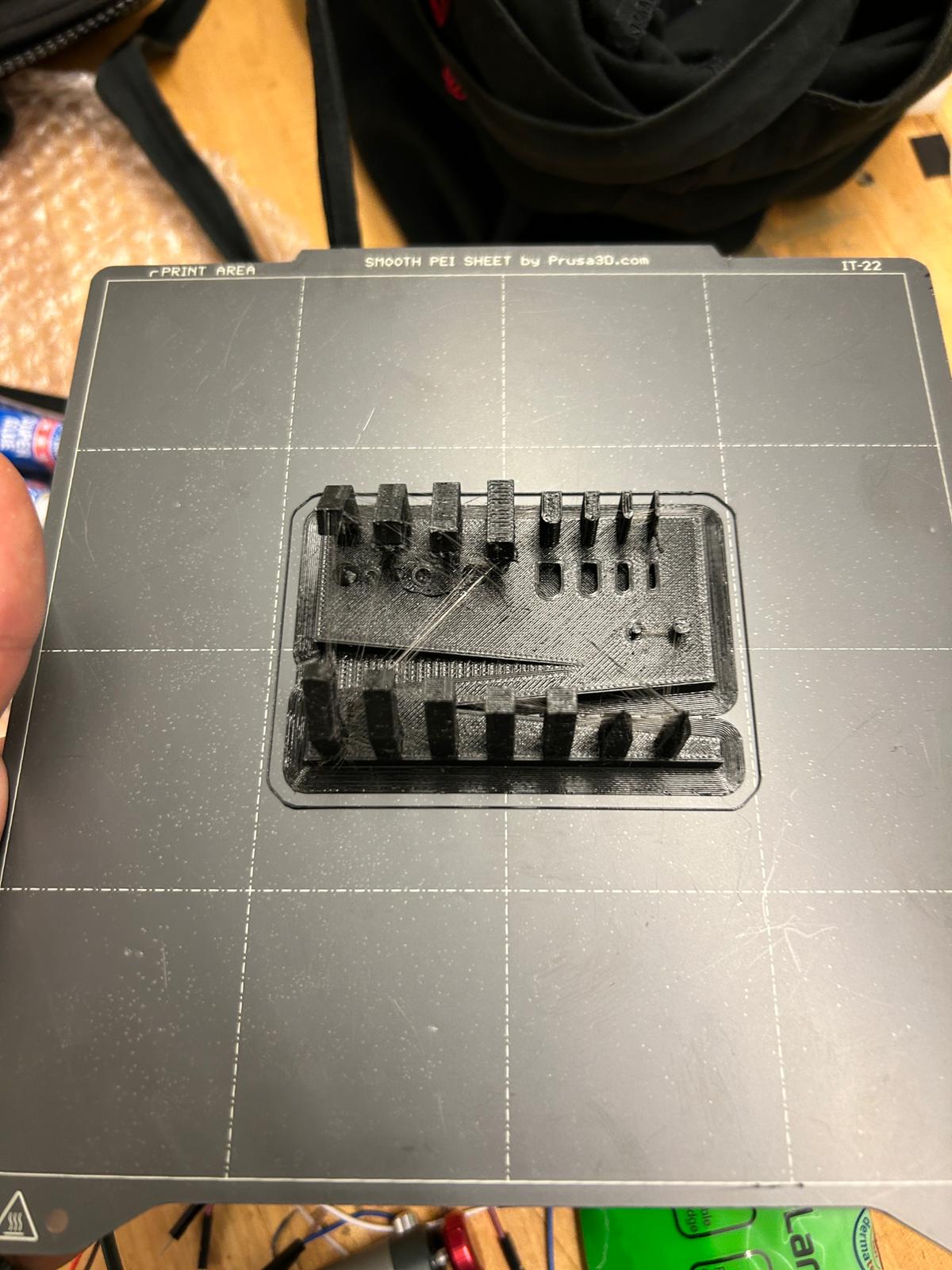
i was not too happy with the outcome. i used a prusa mini with pla filament and a 0.4mm nozzle, but the pla loaded in the printer must have been old, or the nozzle dirty, since it gave me a lot of strings and hair in between the components i tried to print
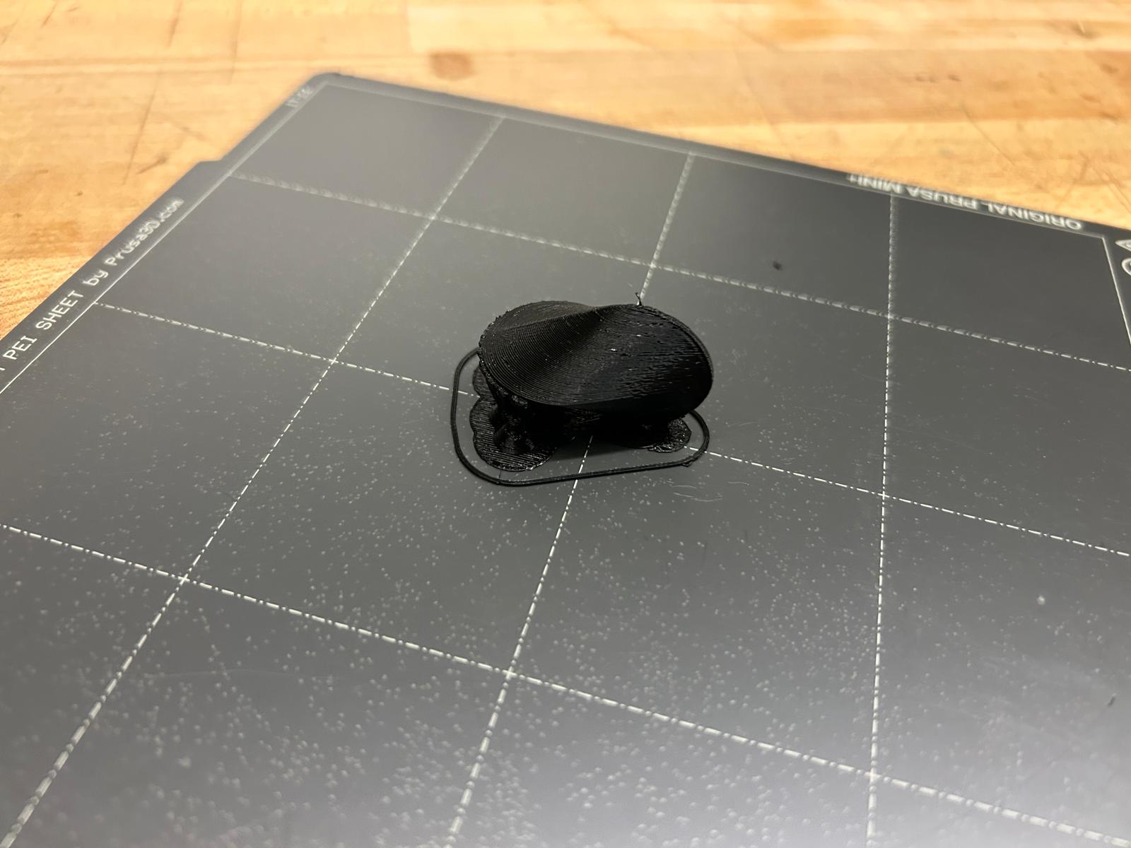
after the initial test, i went forward to print a small object called an oloid, it is a fun object that rolls in a peculiar way, and is made of a developable surface. thefirst print was the solid version, that rolled surpisingly well, despite it's size.
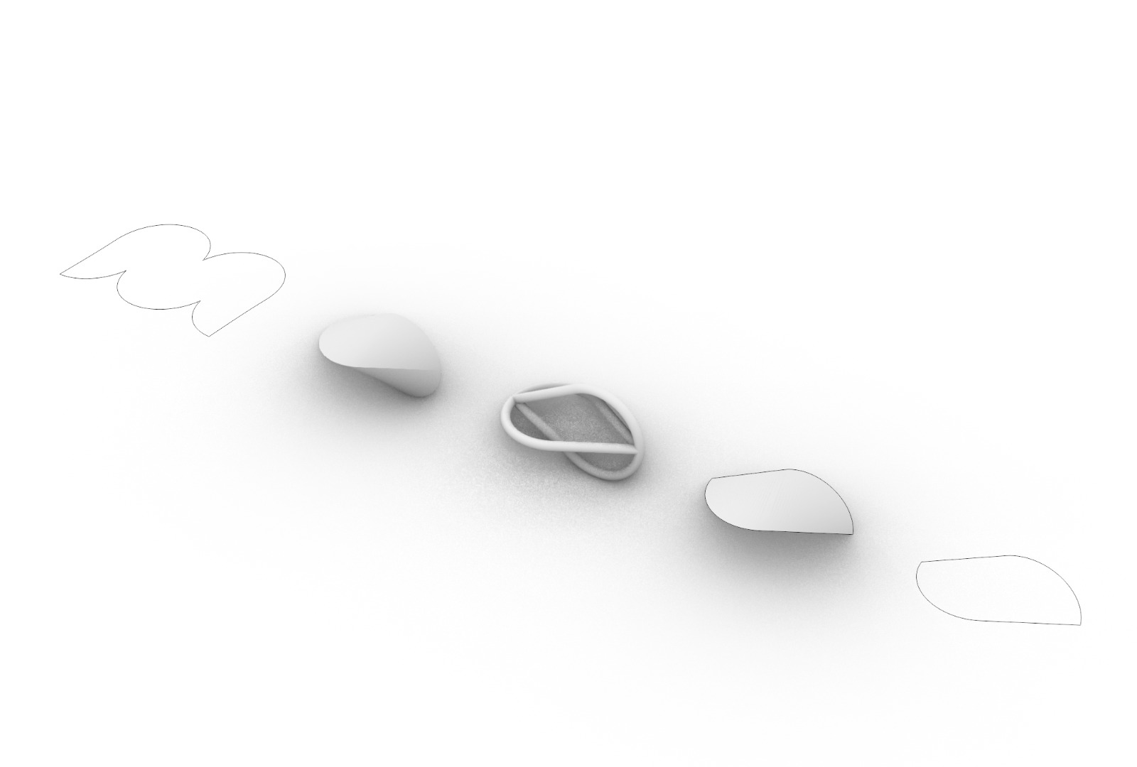
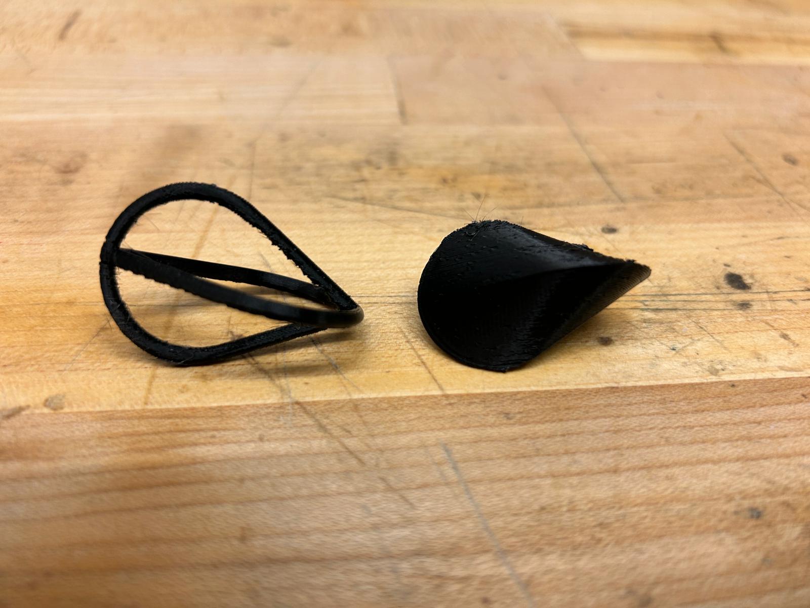
after having tried a couple of roll tests i decided to print another one that is just made of the edges of the object. this made it a lot lighter and actually, it rolled a lot better than the solid version. an explanation for that could be that the idea of this object is that it has an axial center of gravity in theory, this should make the object roll similarly to a cylindrical object. but because the infill was not solid pla, it might have messed with its weight distribution. the version that only represents the edges of an oloid does a much better way in distributing its weight evenly throughout the object and might explain why it rolles so much better.
this model was quite delicate, with only 2mm width at its narrowest point, which is only a few layers of filament extruded to make the shape. it was important to use small clippers and to gentrly cut the supports of the structure since the object itself was about as rigid as the supports that it needed to print.
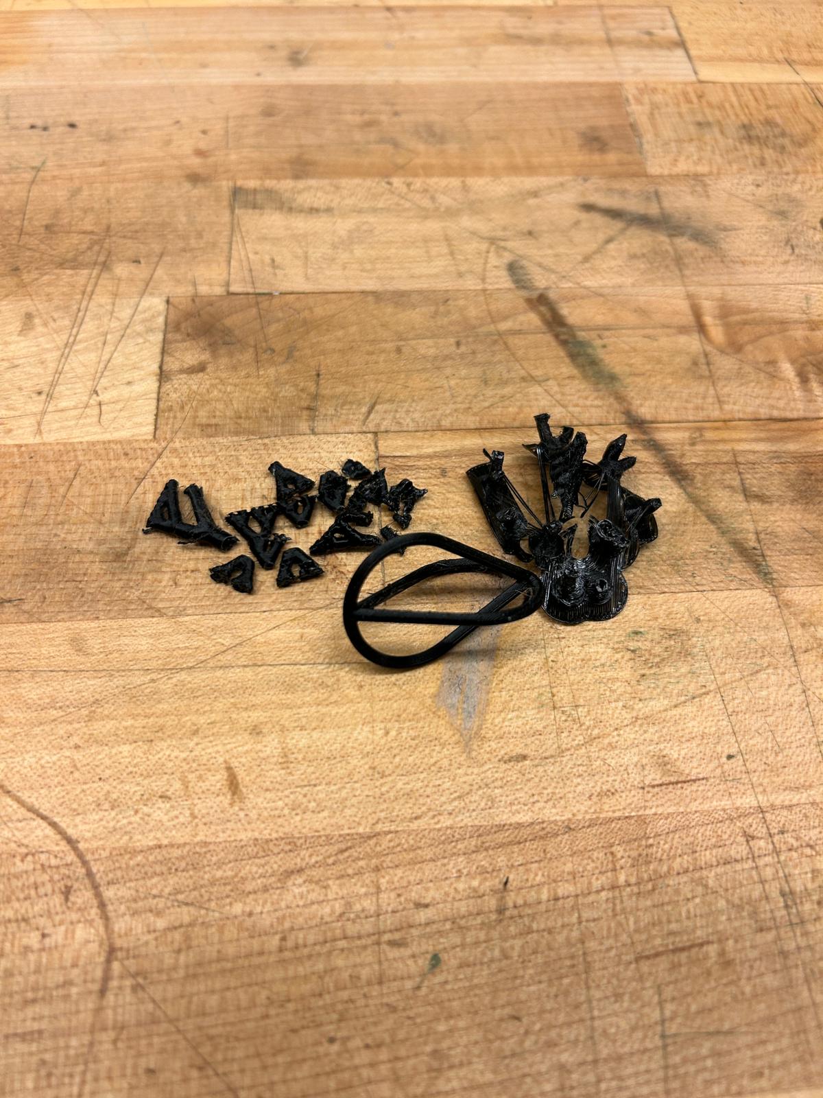
comparison of oloid experiments. note for the future: black filament might look cool, but it photographs horribly
here are the 3d model of the oloids:
oloids rhino model
so it was time to tackle the headach... having 3d modelled my brain, and added a mechanism in the bottom to screw and unscrew a
lid to put things into its inside, i decided to offset the surface mesh of my brain by 1.2mm. this dimension was determined
by the printer and nozzle i intended to use. because of its size, i was not able to print my brain on a prusa mini, but rather
used a prusa i3 mk3s with a 0.6mm nozzle. since the printers would have a hard time making a shell out of a single layer of pla, i
decided to go with 2x 0.6mm = 1.2mm thickness. since the printer buildsthe object up layer by layer, the thinnest parts would only
be a few, as soon as the geometry is not perfectly vertical (which it is almostnever) it will automatically have to put more than
one layer of pla down before moving on.
to double check that my math was correctly executed, i used prusa's slic3r
software. i went into the horizontal slices and went through the simulation of a critical layer to see whether it would be able to
build a new layer of filament ontop of the previous one.
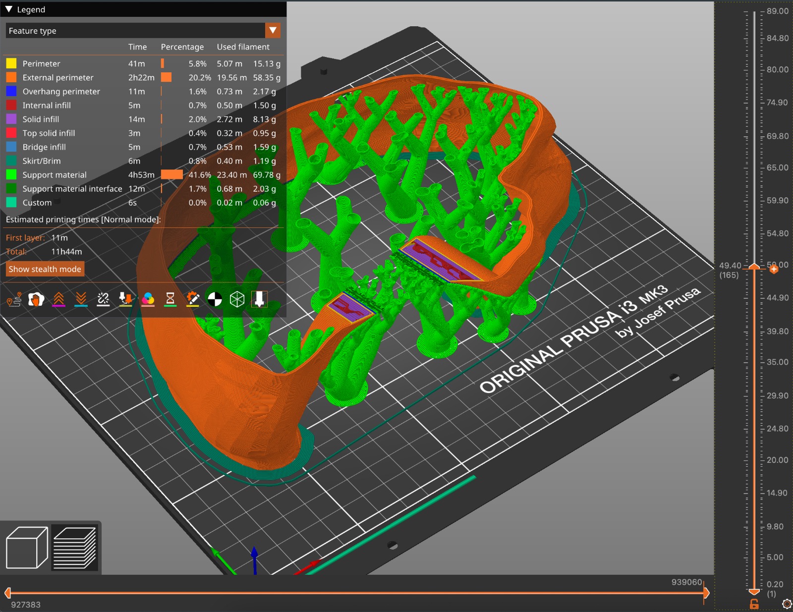
while at this point i trusted the process enough to think that 1.2mm was thick enough, i did not want to test my luck by printing the brain completely without supports (it might have worked because of the geometry). the original printing time was around 30h and it would have printed supports in the inside of the brain, so i decided to print the two sides of the brain into separate print jobs, cutting the printing time per half to roughly 12h each. fortunately, i was able to run two of the same printers simultaneously and was able to stay true to the 12h mark. i started printing one half and let the job run for about an hour before starting the second one. i wanted to make sure that the print and shell would work well before i risked two prints running into issues.
at this point it's worth mentioning, ask your shop managers/monitors/specialists
what filament you are allowed to use on which printers! not every filament
contains the same components to achieve the effect they are supposed to have.
glow-in-the-dark filament, despite being PLA can be really abrasive and hard
on the printer nozzles, especially if they are brass ones (which they normally are).
if you use a filament like this uv-reactive one, it is hard to find info
about its effects on the nozzle... therefore, definitely ask your shop what you are allowed
to use before you spend money on it. the shop in N51 has two printers that they reserve
for more experimental filaments (so that other printers always work for other students)
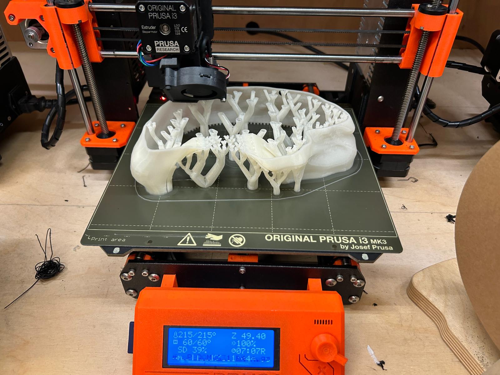
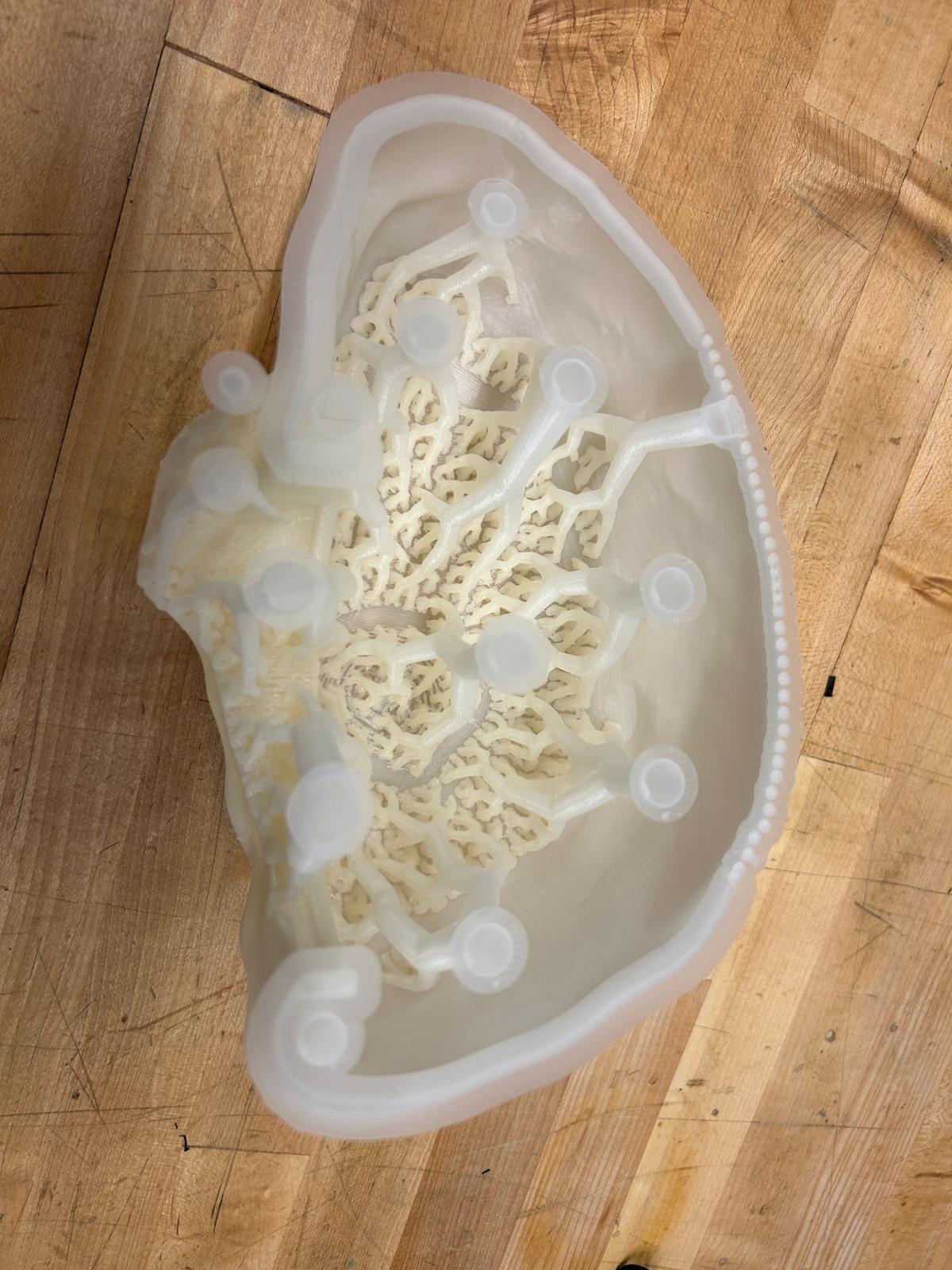
while most normal supports look different, i thought that organiz supports would fit the theme of a brain much better.
they look like little trees or a diagram of nerves.
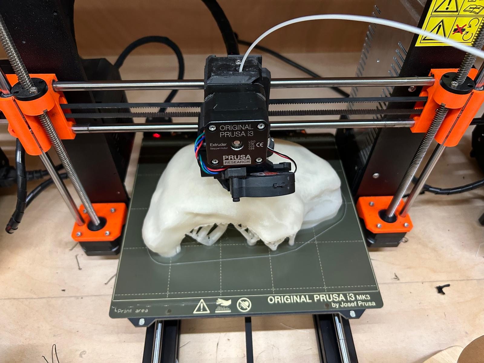
12 hours later it seems to have printed the last few layers almost completely horizontally, solely relying on the support trees it has been building up. this is a scary part. the resolution of the printer in the z-direction is lower than it has in the x and y; adding a new layer is bound to the thickness of the layers, which for a print like that, i had to pump up a little, otherwise it would have taken forever.
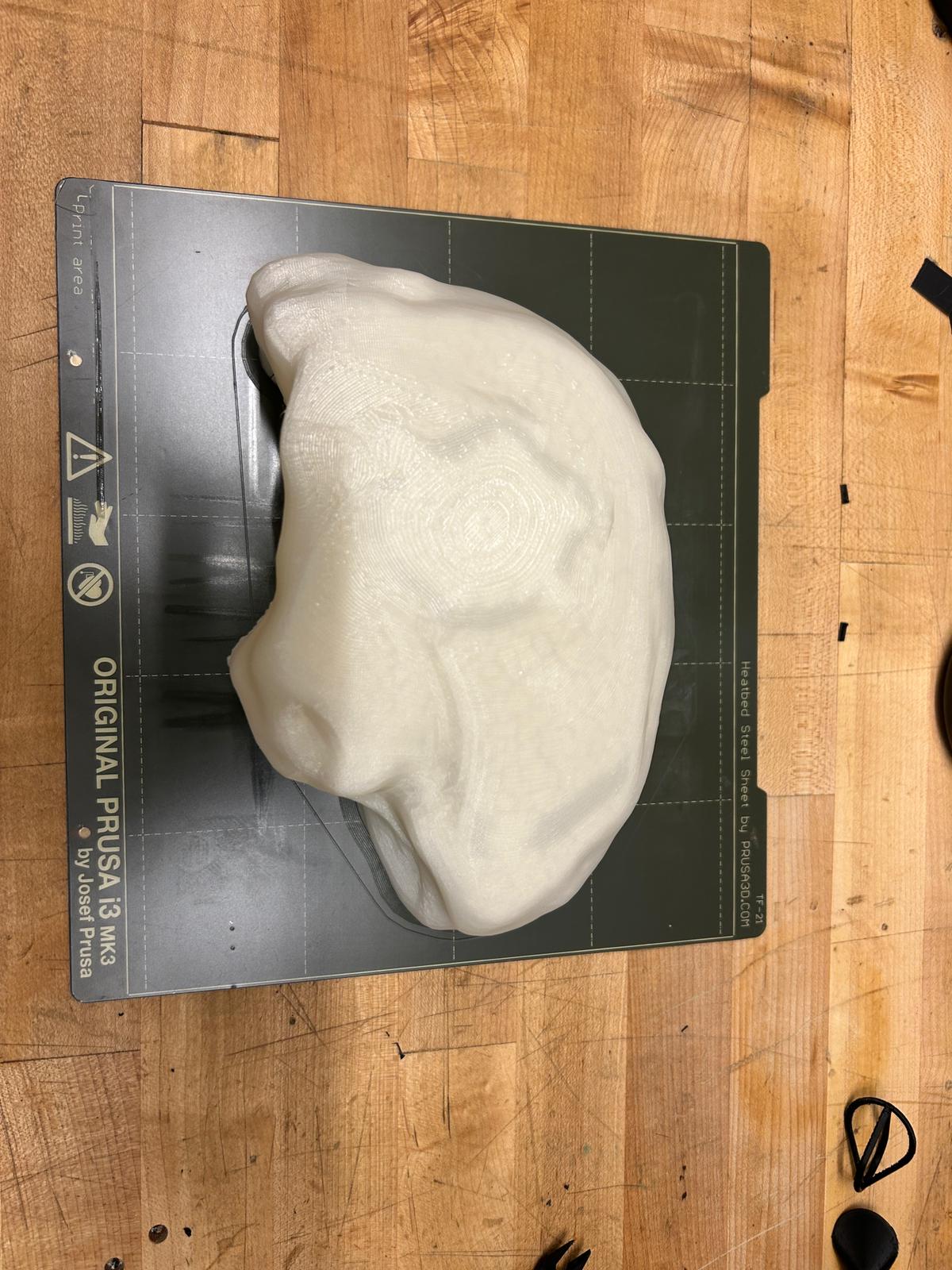
once i remove the print, i let it cool for a bit. i want it to come off the building plate in one piece. i recommend bending the sheet slightly. one can tell when the print pops lose from the building plate.
at this point i wished i didnt have already a plan of what to do with the insight of the brain... unfortunately these tree structures have to go... -.-
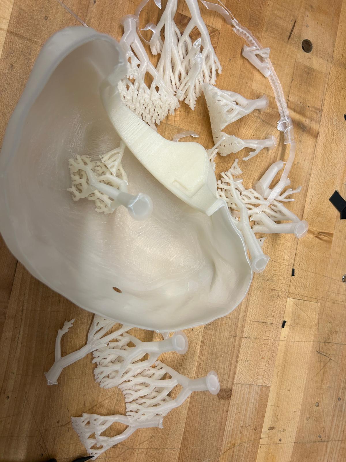
most of the supports came out super easy, however, as i mentioned above, the last layers are not very stable. pulling on the supports too hard, since they are just holding horizontally printed layers, would risk peeling them off (the print is much stronger in x and y than in z direction).
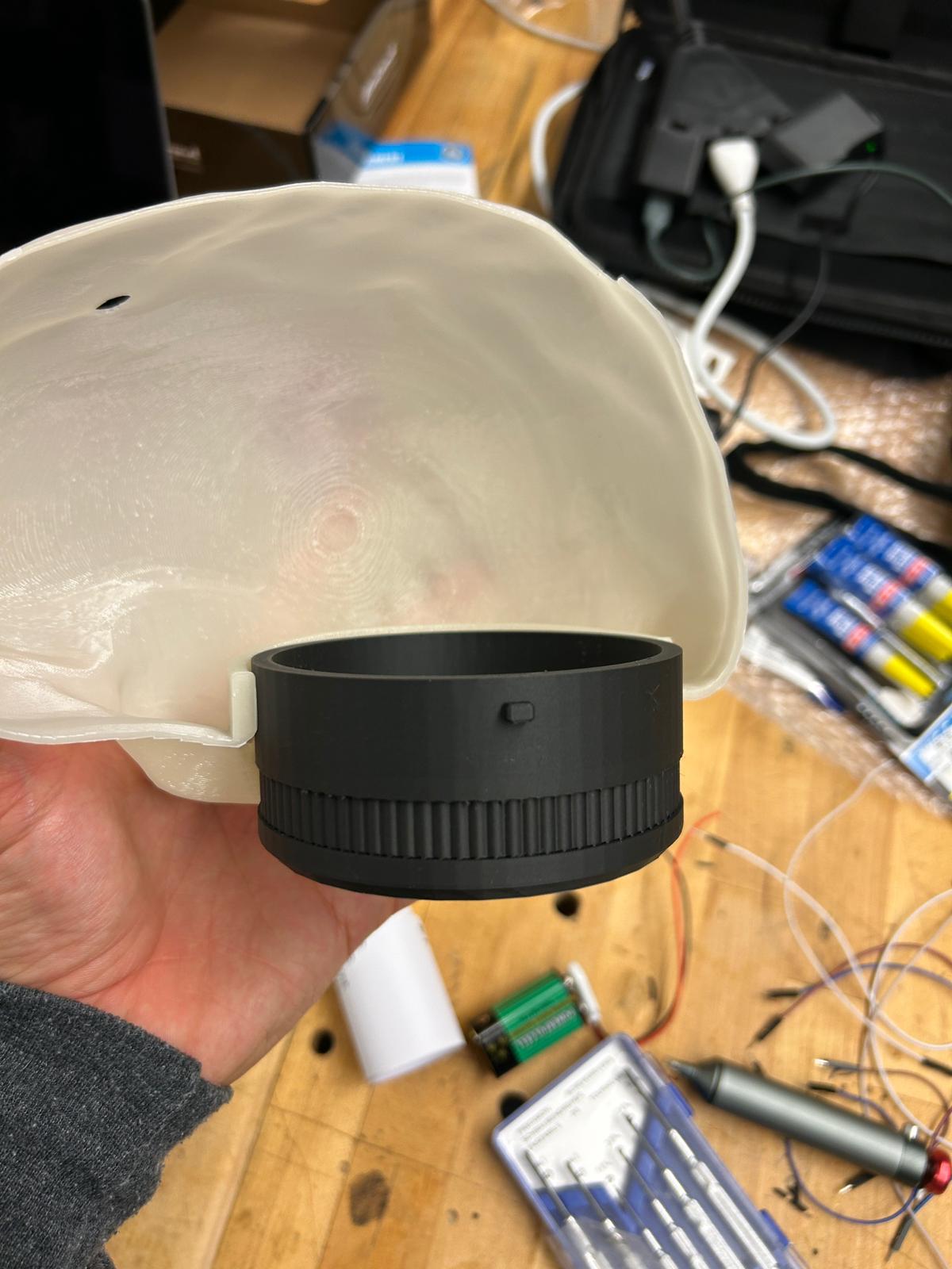
once i have them removed, it is time to try the lid that i printed on a prusa mini in the meantime. once i made sure it would be able to insert and snap shut, it was time to test the other parts.
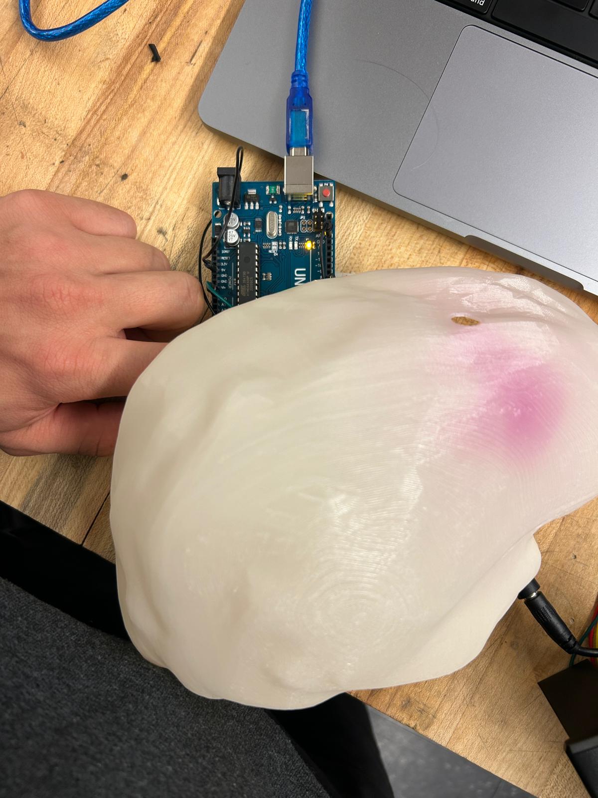
as i mentioned in the beginning, this PLA was supposed to be UV reactive (here ist the PLA i got from microcenter for this print - Inland 1.75mm PLA UV Color Change 3D Printer Filament 1.0 kg (2.2 lbs.)) it was already dark out when i got to this point, and i did not have any uv light source available but a few lose uv leds NTE Electronics UV Purple Discrete 3mm LED Indicators - 10 Pack that i got also at microcenter. so i decided to hook them up to an arduino uno and a bread board to see what the PLA would do.
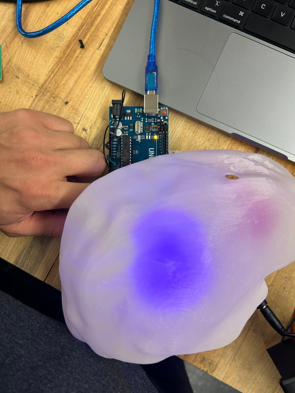
while the uv leds are one, they are visible as violet/blue shine through the print. i set them up to light up for 10 seconds in arduino.
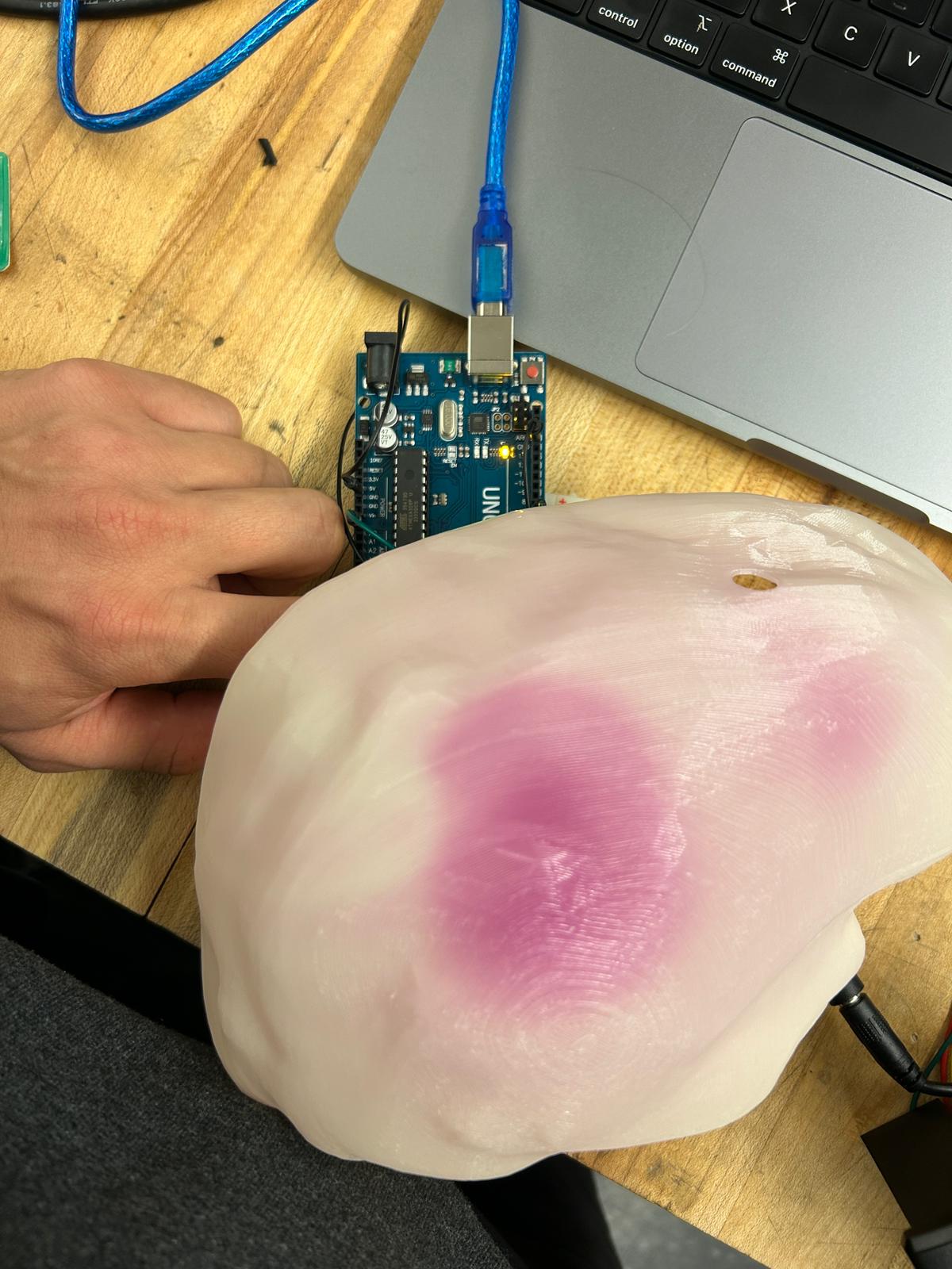
as soon as they turn off, the PLA remains red for a few minutes before changing the color back to white! pretty fun
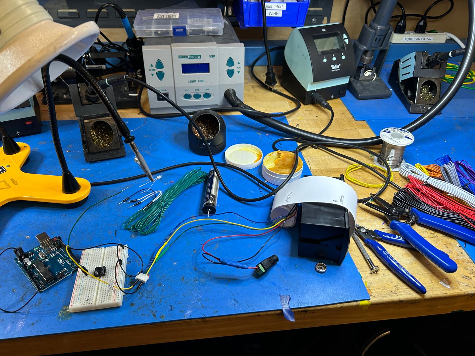
once i had it all figured out, i just soldered all the wires together, added a button that was originially mounted on the brain (would fall off later), and soldered a power
plug that would act as external power supply (9-12v) for the receipt printer.
to run the thermal printer on the arduino uno i needed to install and include the "Adafruit_Thermal.h" and "SoftwareSerial.h" library.
here is a test example code:
                    #include "Adafruit_Thermal.h"

#include "SoftwareSerial.h"
#define TX_PIN 6
#define RX_PIN 5

SoftwareSerial mySerial(RX_PIN, TX_PIN);
Adafruit_Thermal printer(&mySerial);

const int btnPin = A0;
int btnVal = 0;
void setup() {
pinMode(btnPin,INPUT_PULLUP);


pinMode(7, OUTPUT); digitalWrite(7, LOW);


mySerial.begin(9600);

printer.begin();


}

void loop() {
btnVal=analogRead(btnPin);
if(btnVal<200){ // We press the push button
 printer.println(F("Arduino"));
}
}
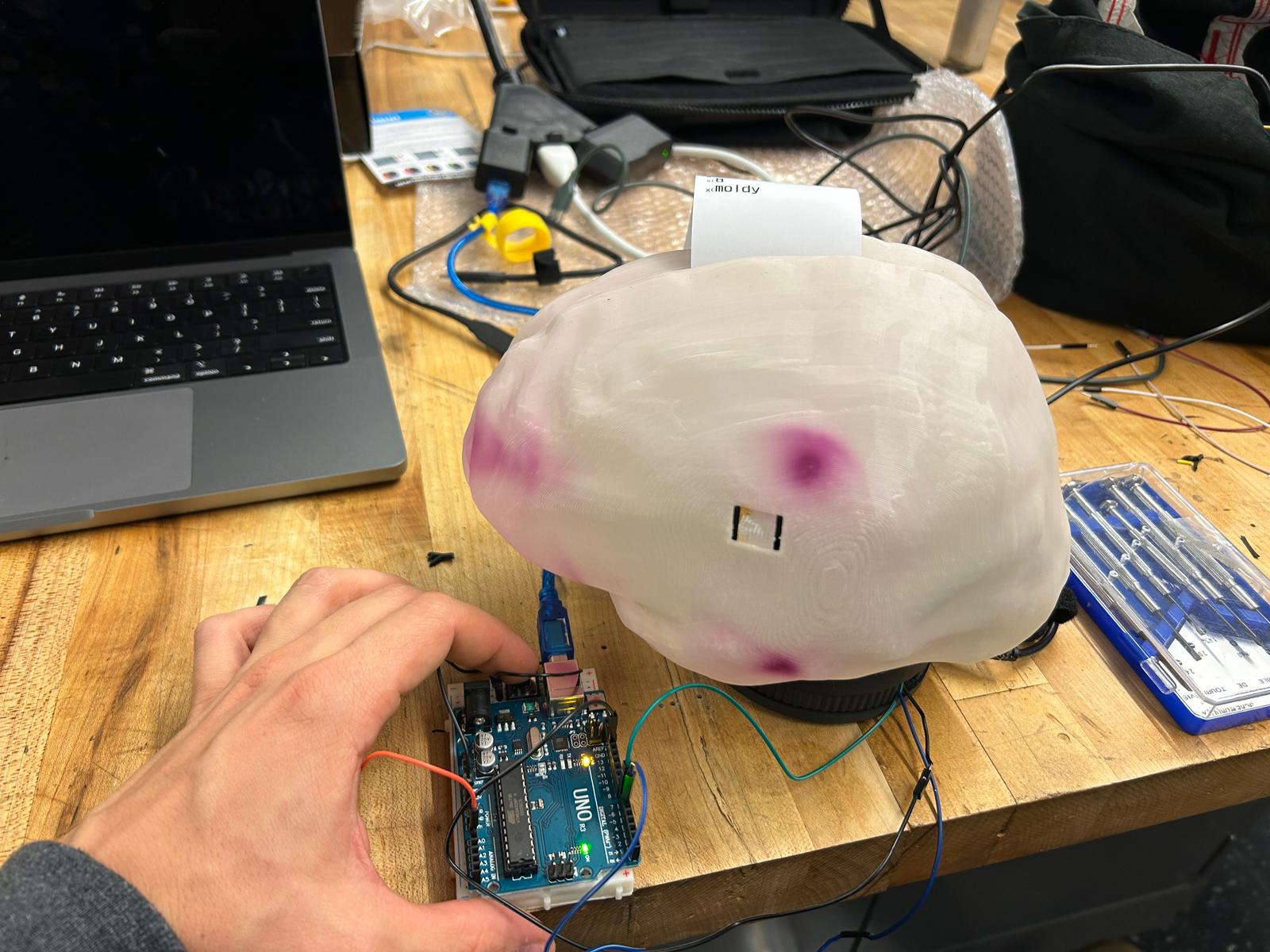
for the final result i hoped to have the arduino pick random dictionary entries and prints them out including the definitions,
but the internal memory of the arduino uno's are not big enough so i included merely a few words... but that worked. I hope i get
to make my own pcb with a memory card and or wifi connectivity to parse the information from the internet, or get a voice to text interpreter,
that could run a ChatGPT token to have a physical chat interface.
for now, i'm happy i made it work that far. here is the code i used:
                    #include "Adafruit_Thermal.h"
#include "SoftwareSerial.h"

#define TX_PIN 6
#define RX_PIN 5

SoftwareSerial mySerial(RX_PIN, TX_PIN);
Adafruit_Thermal printer(&mySerial);

const int btnPin = A0;
const int ledPin = 7;
int btnVal = 0;
unsigned long previousMillis = 0;
const long ledDuration = 10000;  // LED duration in milliseconds (10 seconds)
bool printed = false;  // flag variable to track printing status

// collection of strings
const char* phrases[] = {
      "long-term",
      "gruesome",
      "like",
      "gabby",
      "separate",
      "average",
      "deeply",
      "moldy",
      "addicted",
      "taboo",
      "handsome",
      "confused",
      "languid",
      "exultant",
      "majestic",
      "spicy",
      "various",
      "disastrous",
      "cloudy",
      "knowledgeable",
      "necessary",
      "worthless",
      "breakable",
      "tough",
      "limping",


};


void setup() {
    pinMode(btnPin, INPUT_PULLUP);
    pinMode(ledPin, OUTPUT);  // set the LED pin as an output
    digitalWrite(ledPin, LOW);  // LED is initially off
    mySerial.begin(9600);
    printer.begin();
    printer.setSize('L');
}

void loop() {
    btnVal = analogRead(btnPin);

    if (btnVal < 200 && !printed) {  // button pressed and not printed yet
        digitalWrite(ledPin, HIGH);  // turn on LED
        printed = true;  // set the flag to indicate that printing happens
        previousMillis = millis();  // save current time

        // pick a random index
        int randomIndex = random(0, sizeof(phrases) / sizeof(phrases[0]));

        // printing
        printer.println(phrases[randomIndex]);

        printer.println("\n\n\n\n\n\n\n\n\n\n\n\n\n\n\n\n\n\n");
    }

    // check if the LED time is over, then reset
    if (printed && millis() - previousMillis >= ledDuration) {
        printed = false;
        digitalWrite(ledPin, LOW);  // turn off LED
    }
}
because the images i used to model my brain are actual medical records, i do not want to share the 3d model of it, sorry for that.