#7 Chairpants
this week, we were tasked to use a large format machining process
to "make something big". the class provided us with OSB, which is
wood chips glued and pressed into an awefull mess of a board material.
as you might have noticed so far on my website, i use the hot dog as
a cursor, because i think its fun... but on this page i decided to
make it into a an osb cursor. to follow niel's explanation:
"OSB is the hot dog of plywoods"
the way i did this was to define two different "pointers" in the style.css document of my website, the first one
calls the hotdog image, and the second one the osb:
.pointer {
    cursor: url(./assets/cursor.png) 0 0, auto;
}
.pointer2 {
    cursor: url(./assets/osb_cursor.png) 0 0, auto;
}
after that was done, i just needed to implement it in the html code of this page:
setup and nav bar information....

<*div class="split-container">
<*div class="left-side">
<*div class="pointer2">

... content (remove the * symbols)
all jokes aside, or maybe not, but this week i decided to make 3 different objects. i collaborated with mateo who designed, milled, and fabricated with me two objects. we decided to make two objects that would be useful to our apartments and experiment with two different sets of joinery.
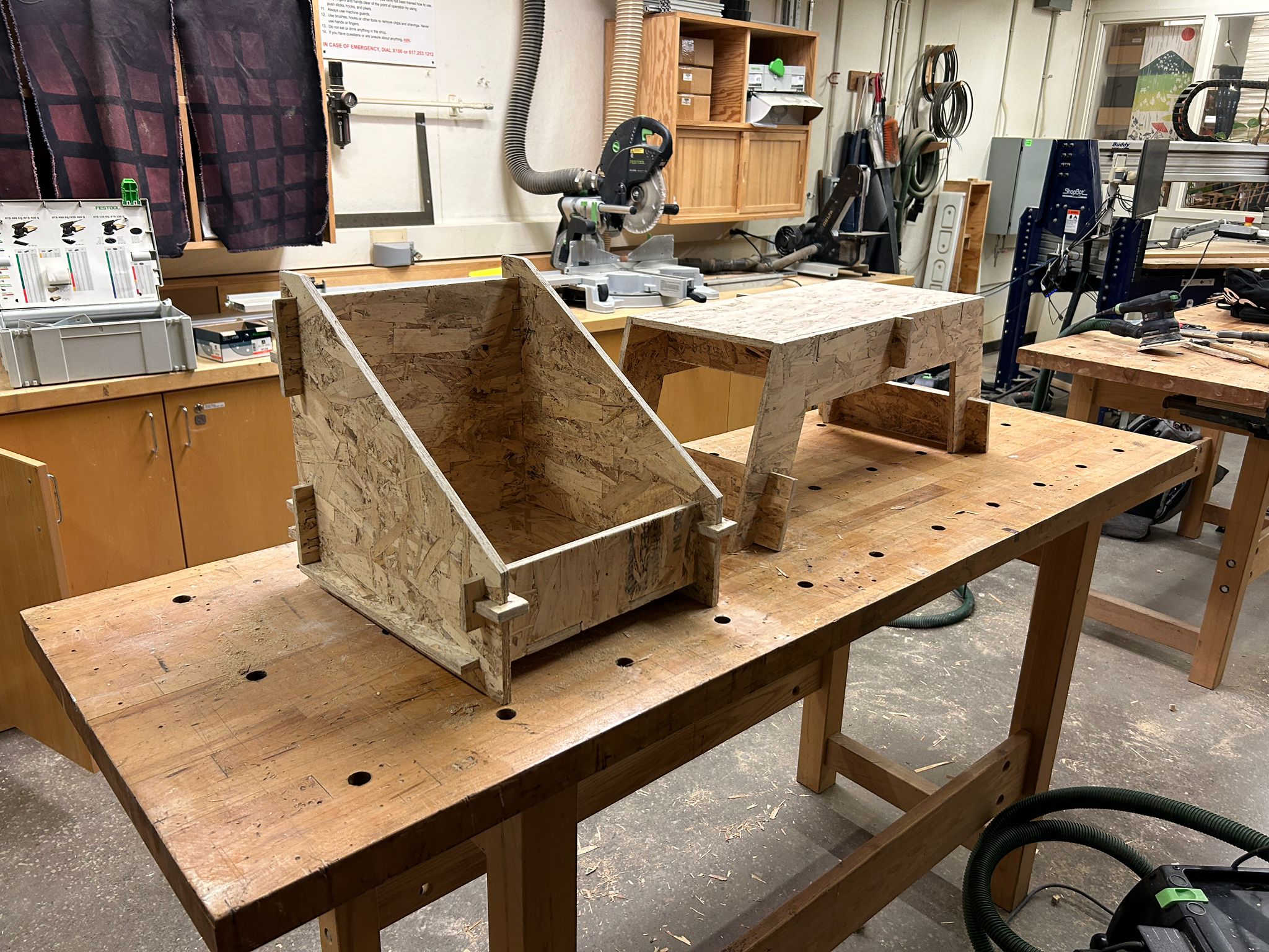
we started working on a box to hold records, as well as a little foot stool
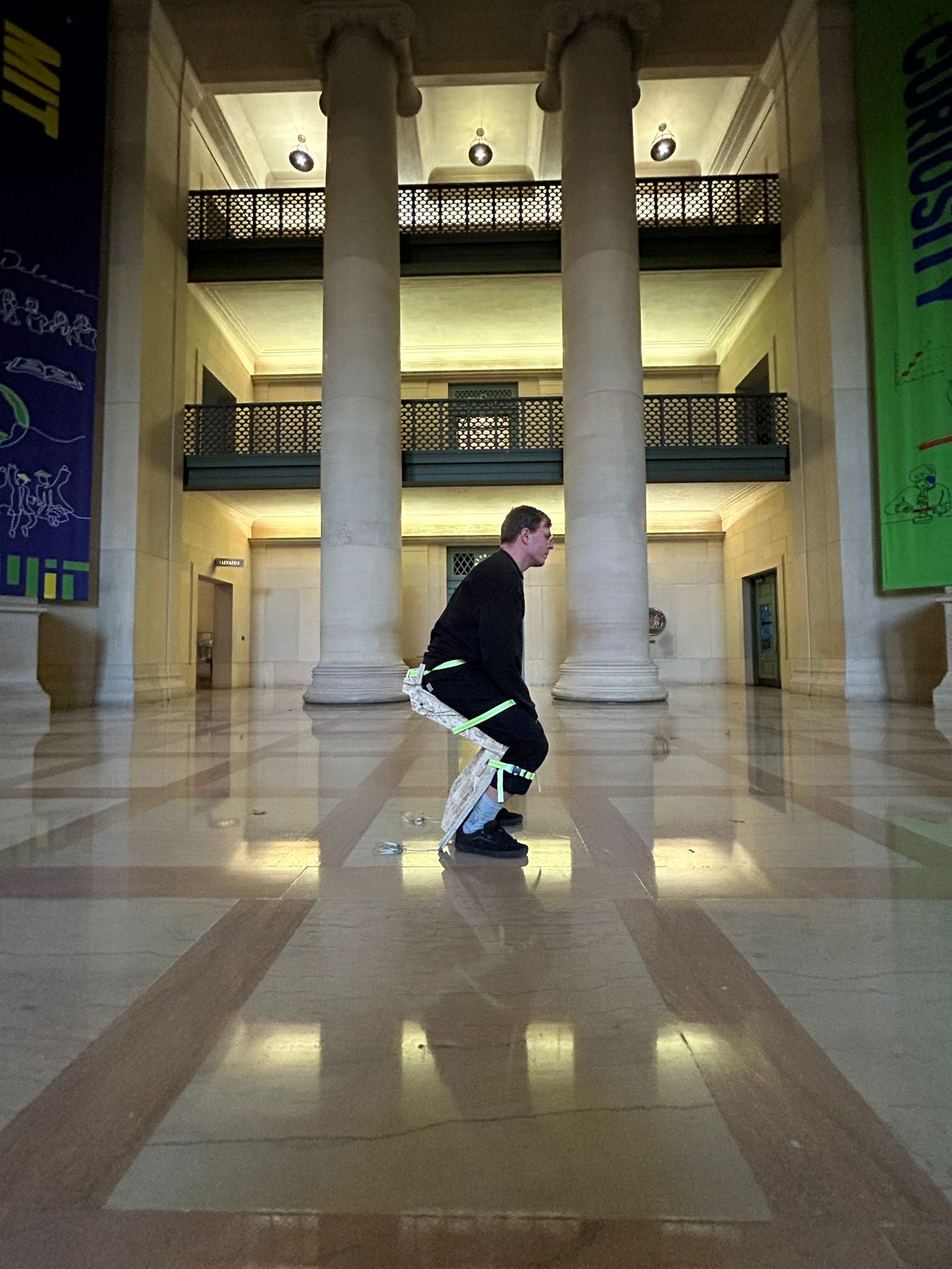
additionally i decided to make chair-pants, a device that would let you sit wherever you go ( - - see right hand part of the website for the documentation)
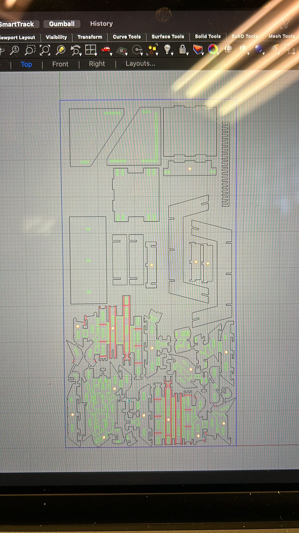
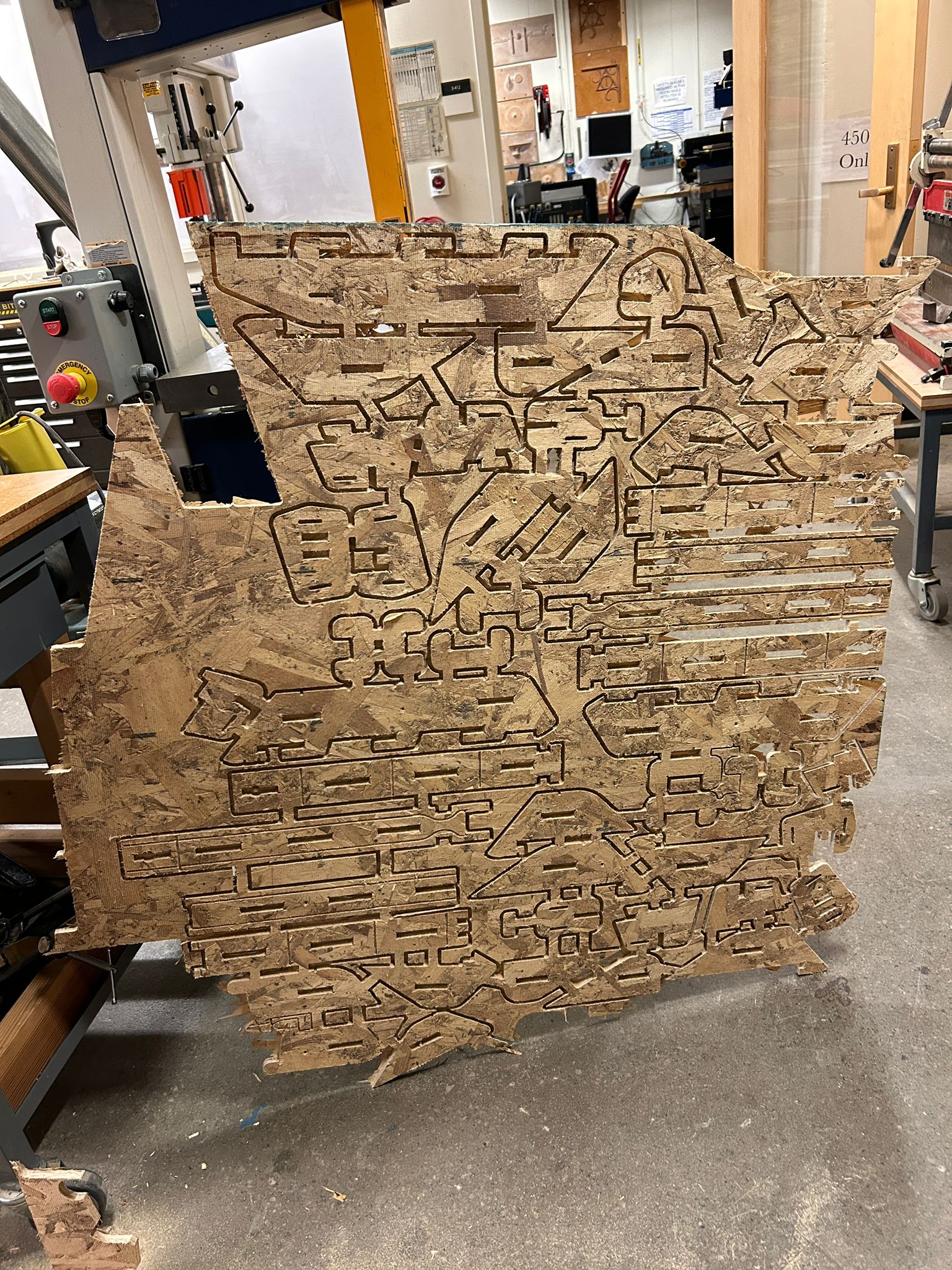
first things first, we designed our objects and layed them out on a 4ft x 8ft sheet of osb, and tried to make all the things we wanted to make on a single sheet of osb. the top pieces are for the elements of the foot stool and record box and the small ones on the bottom are for the chair pants.
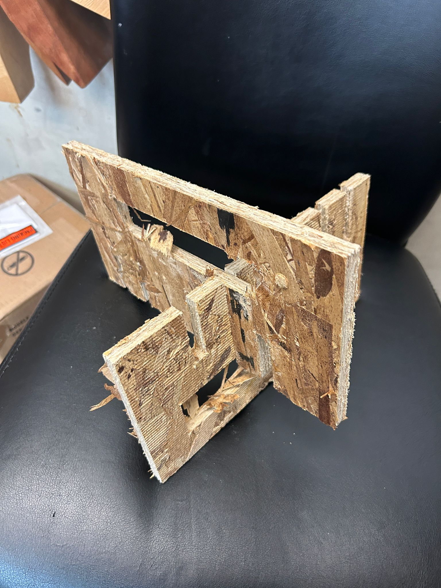
after working on the group assignment, we set up the onsrud cnc mill, got safety training on the shop and the cnc machine in particular, set up the milling file using MasterCAM, loaded the material and fixed it into the machine, and cut a test piece to test the tolerances for notches for pressfit joinery.
Mateo and I decided to work together on some furniture experiments,
we decided to make a small foot rest as well as a box for records using only press-fit joinery ideas.
download the 3d files for them here:
footrest and record box
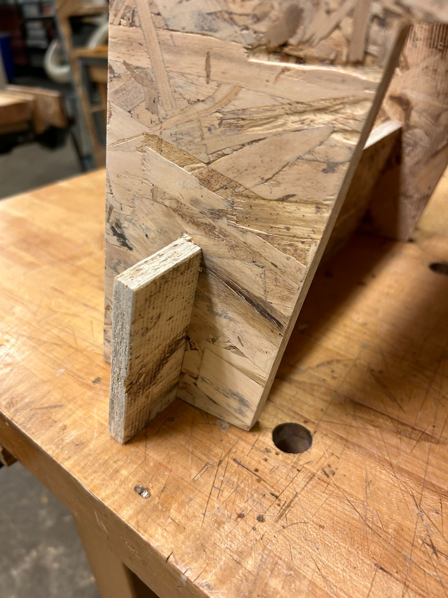
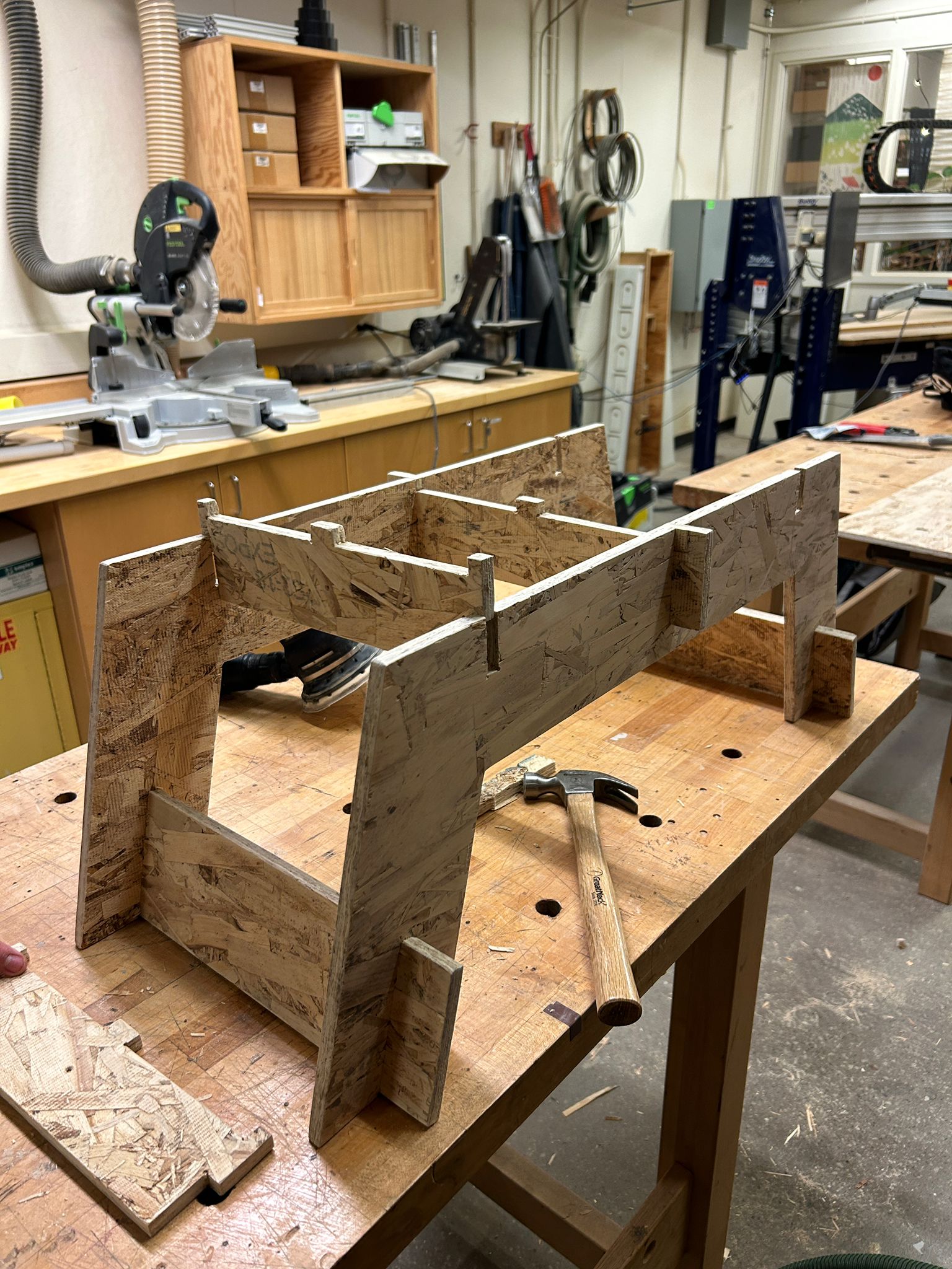
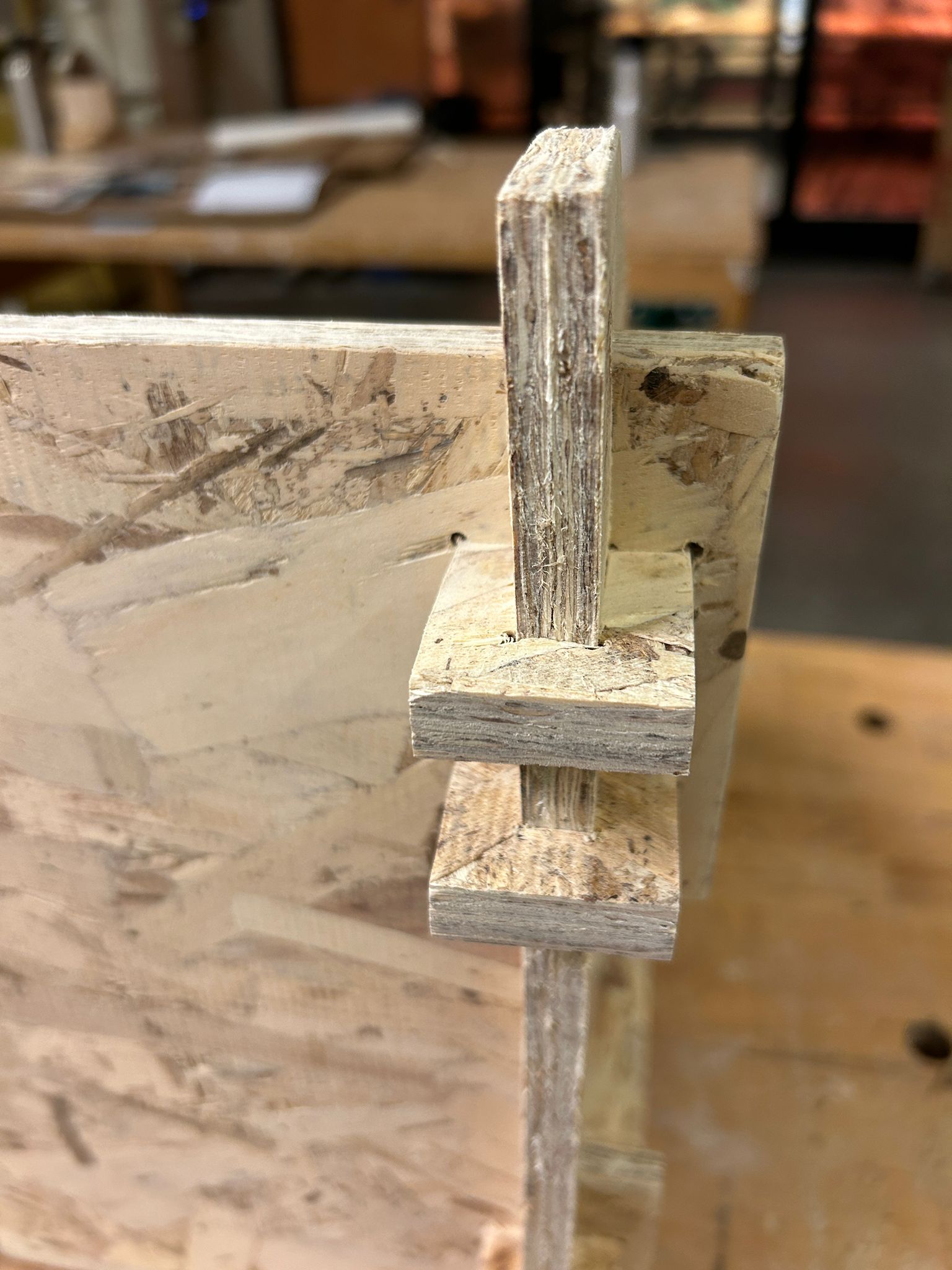
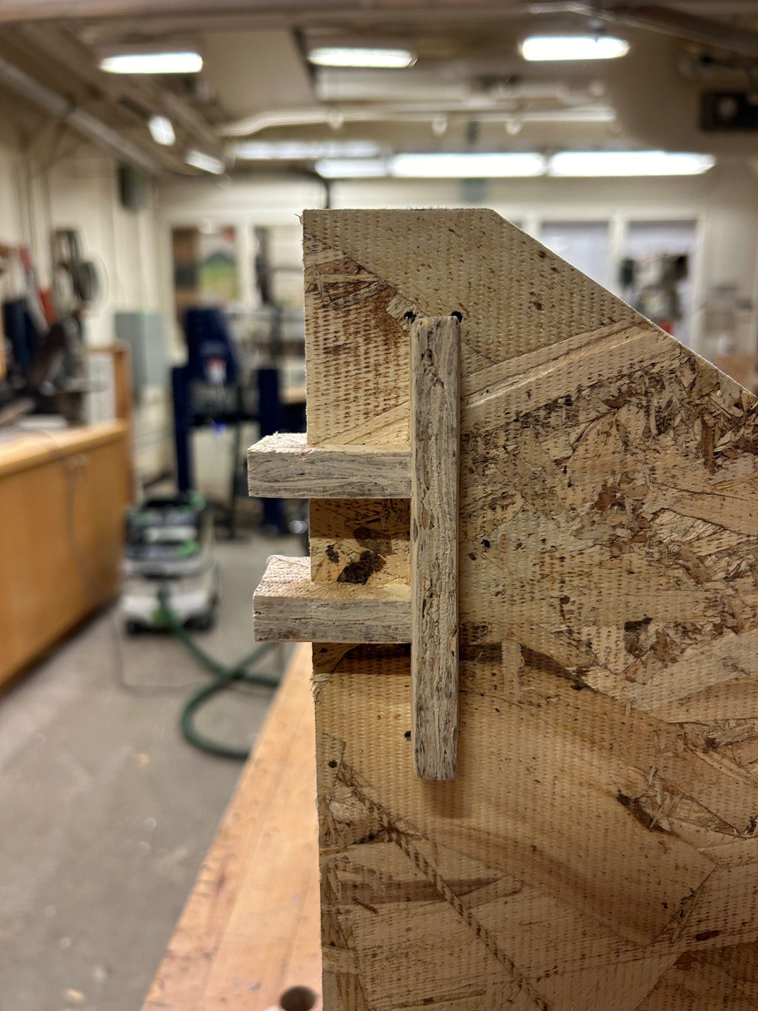
all the parts are press-fit, not only to hold the panels together, but also to stabilize it enough so it cannot sheer
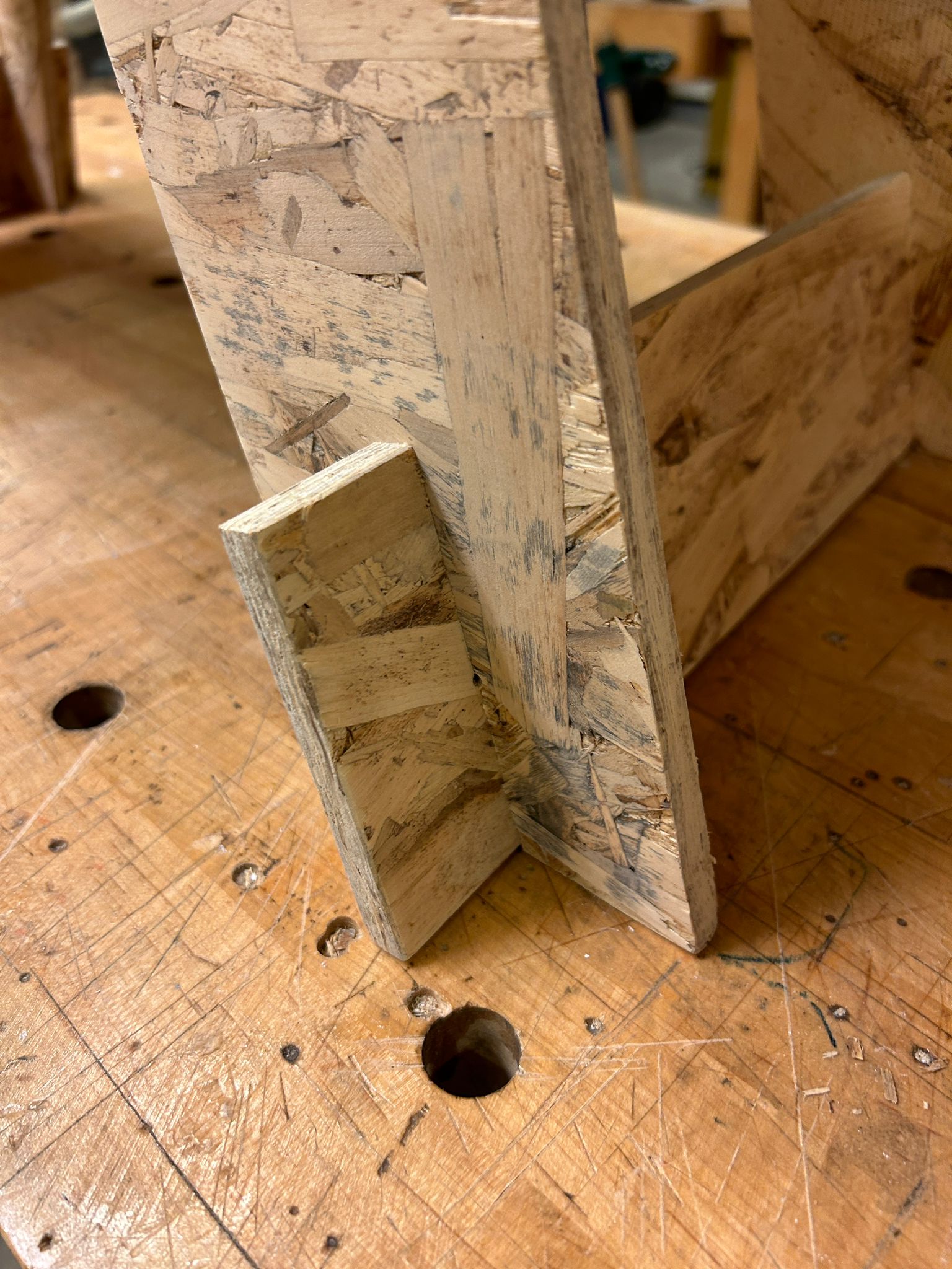
the cross braced elements are put in through the top, finished off witht the top board that will keep them in place. there are some holes in the top plate that the cross-bracing brakets are notching into to further stabilize the structure. since this is something my partner might put her feet on, i decided to send it off with 120, 200, and 400 grid sand paper.
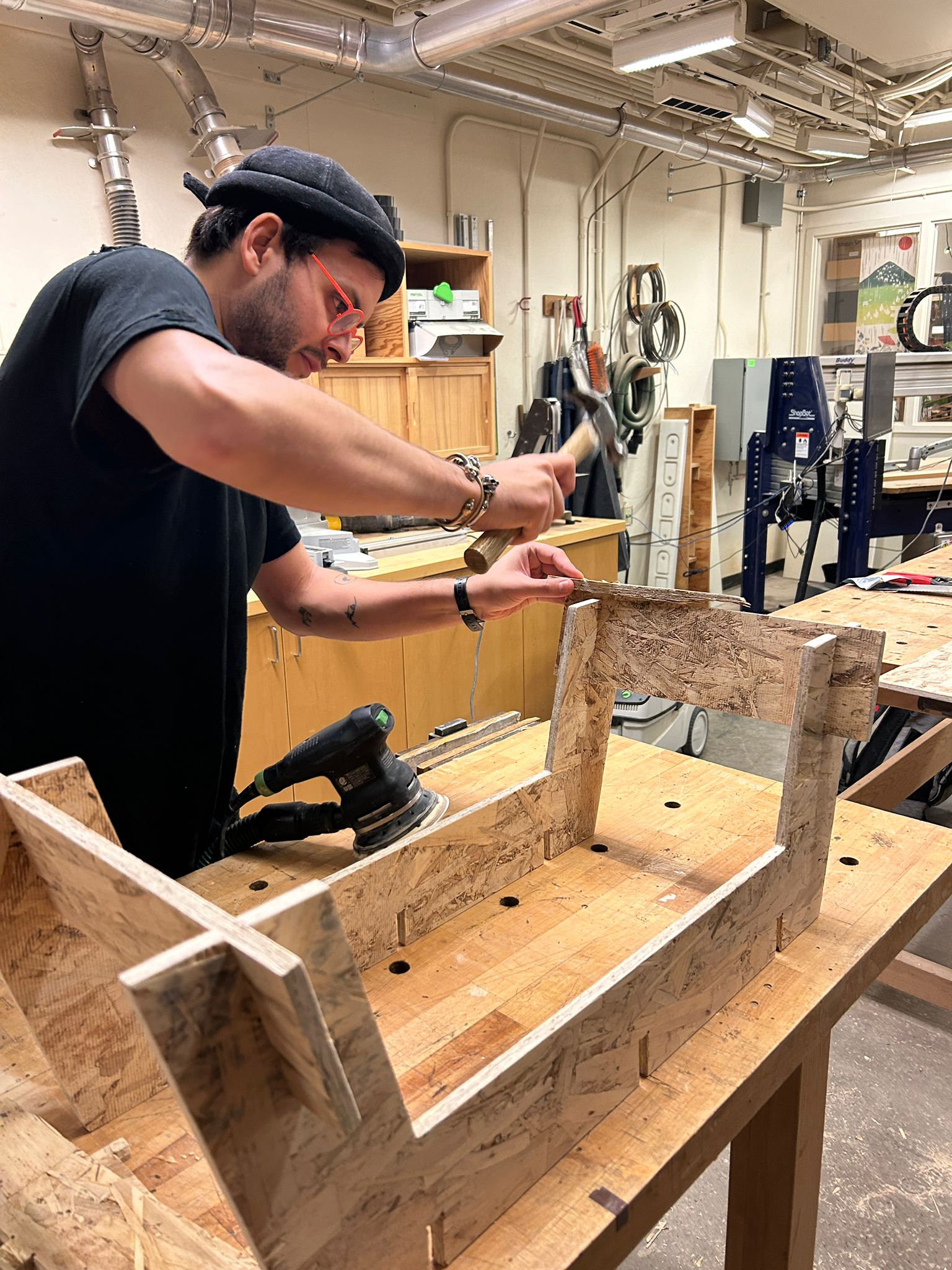
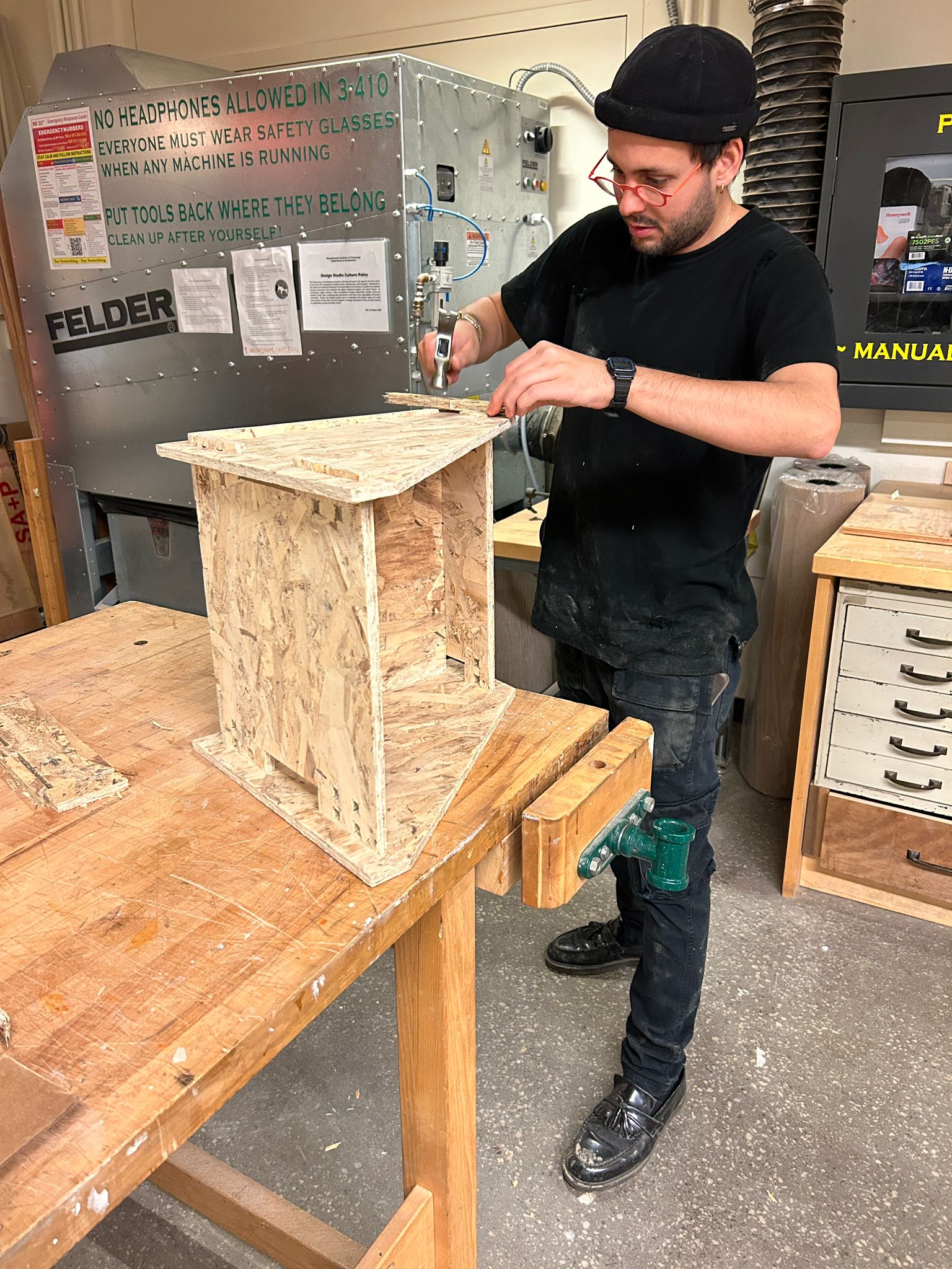
the tolerance of the material and the roughness of the cross cross section are enough to make some pieces go in quite hard, but will ensure that once in place, they will hold well. so we decided to just sand them very little, to get a smooth surface finish, but not to take too much material away that might otherwise cause a too lose fit. we placed an off-cut piece of wood in when hammering in the individual cross-braces.
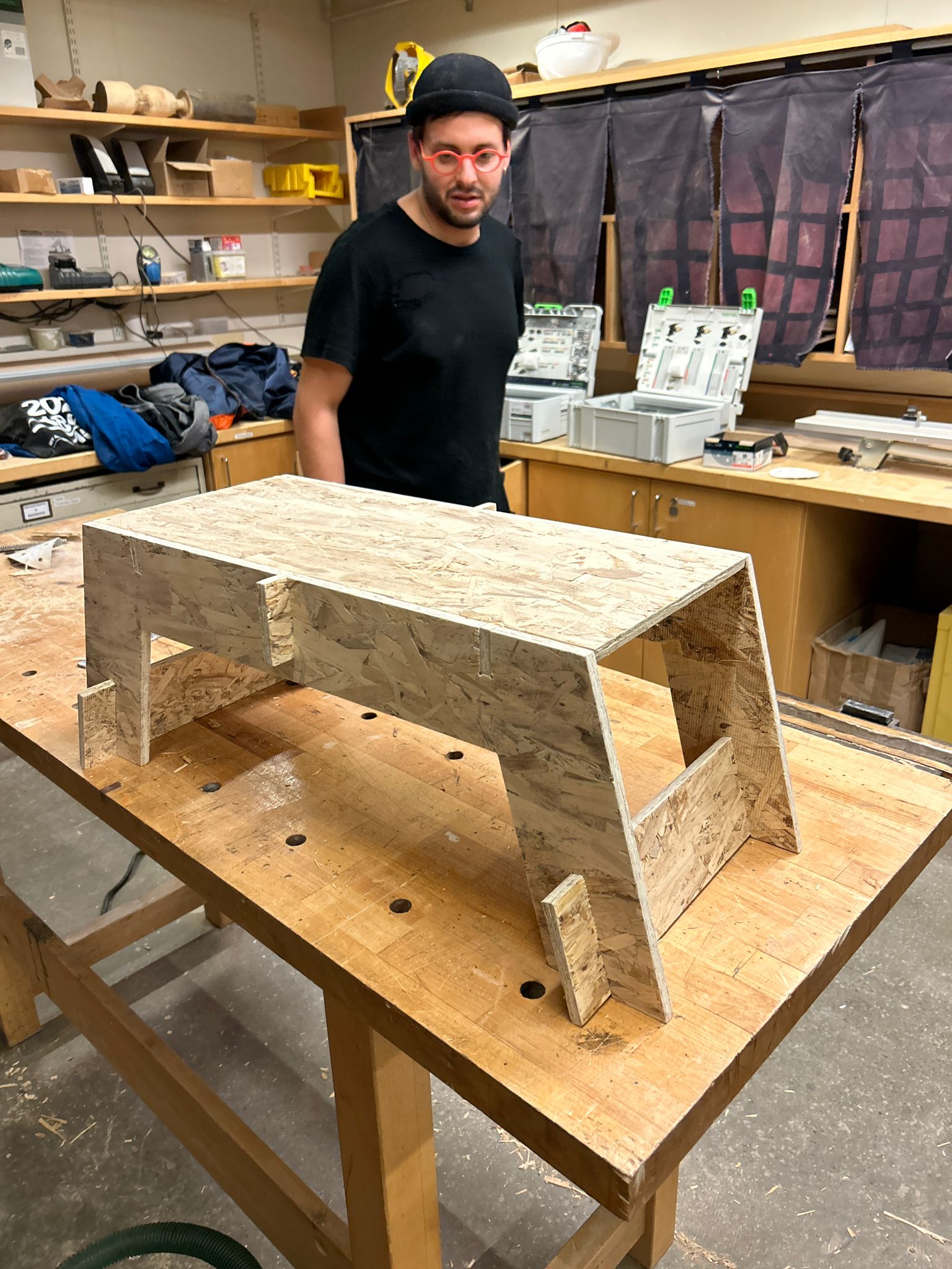
the final result of the foot stool.
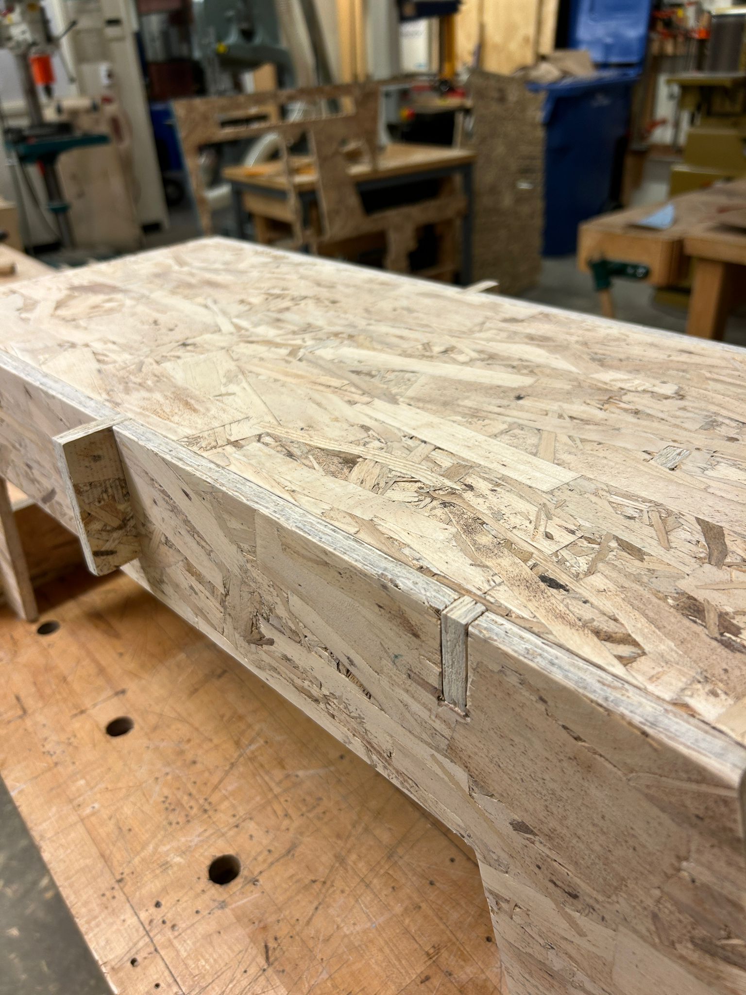
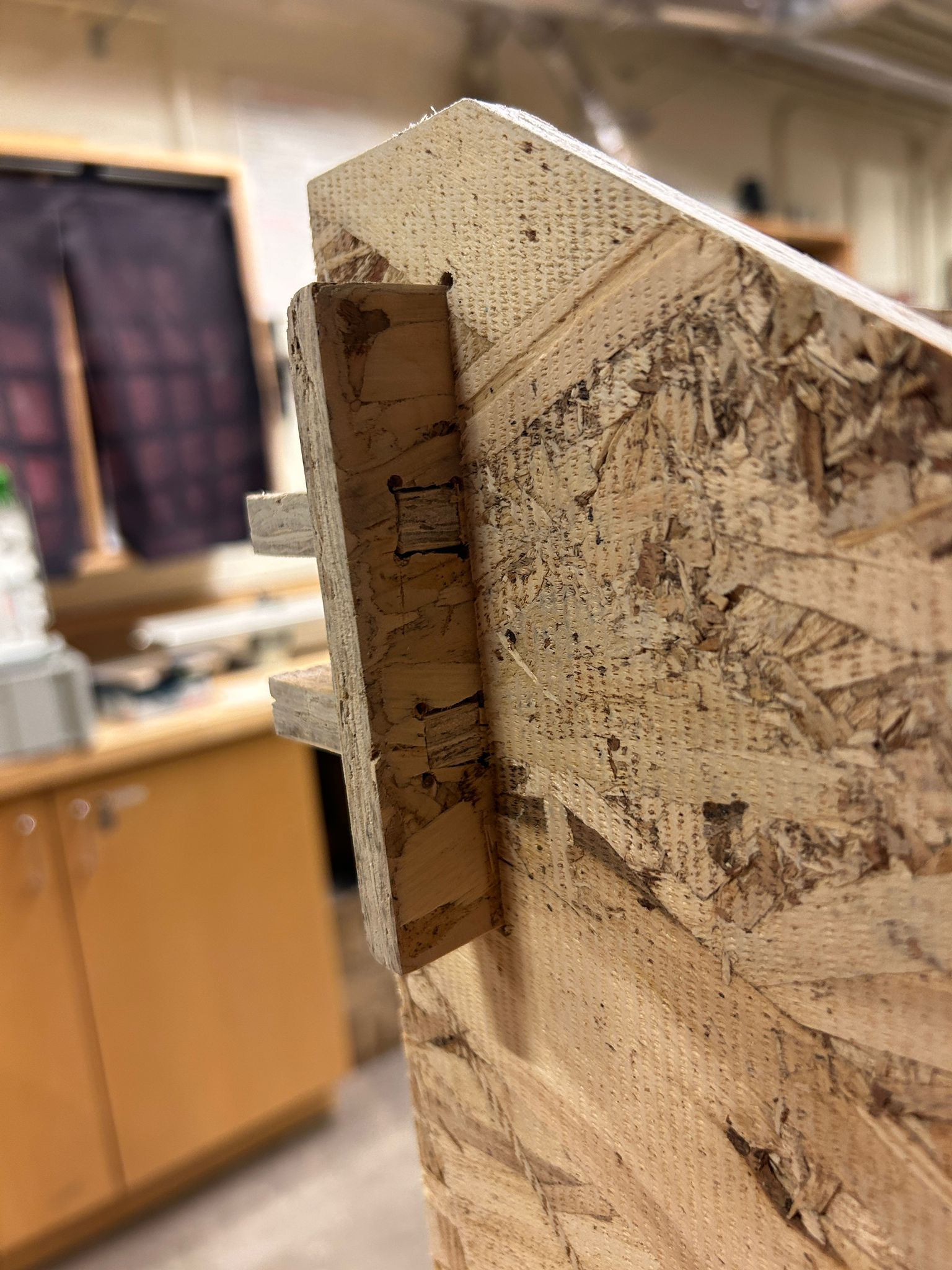
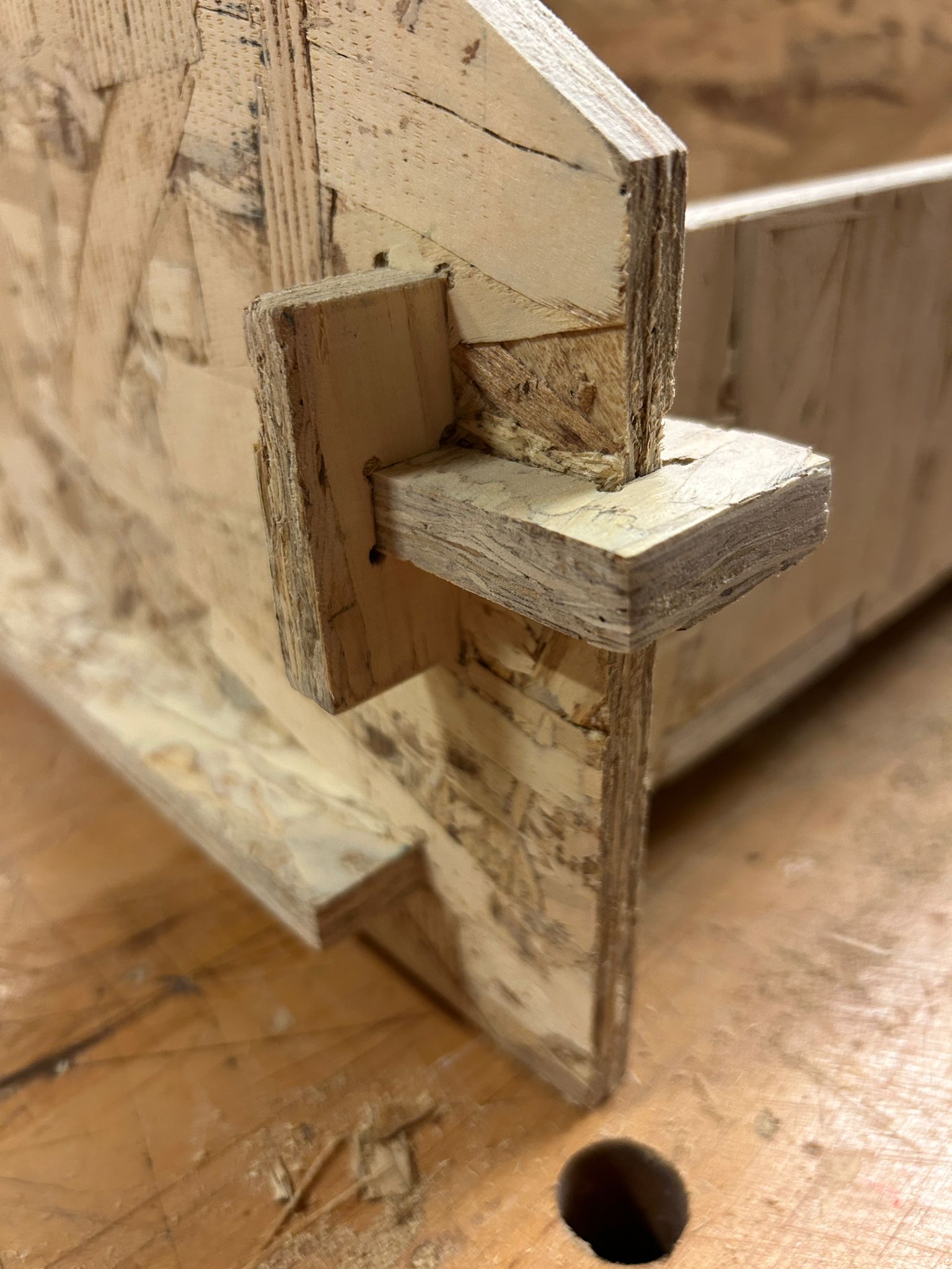
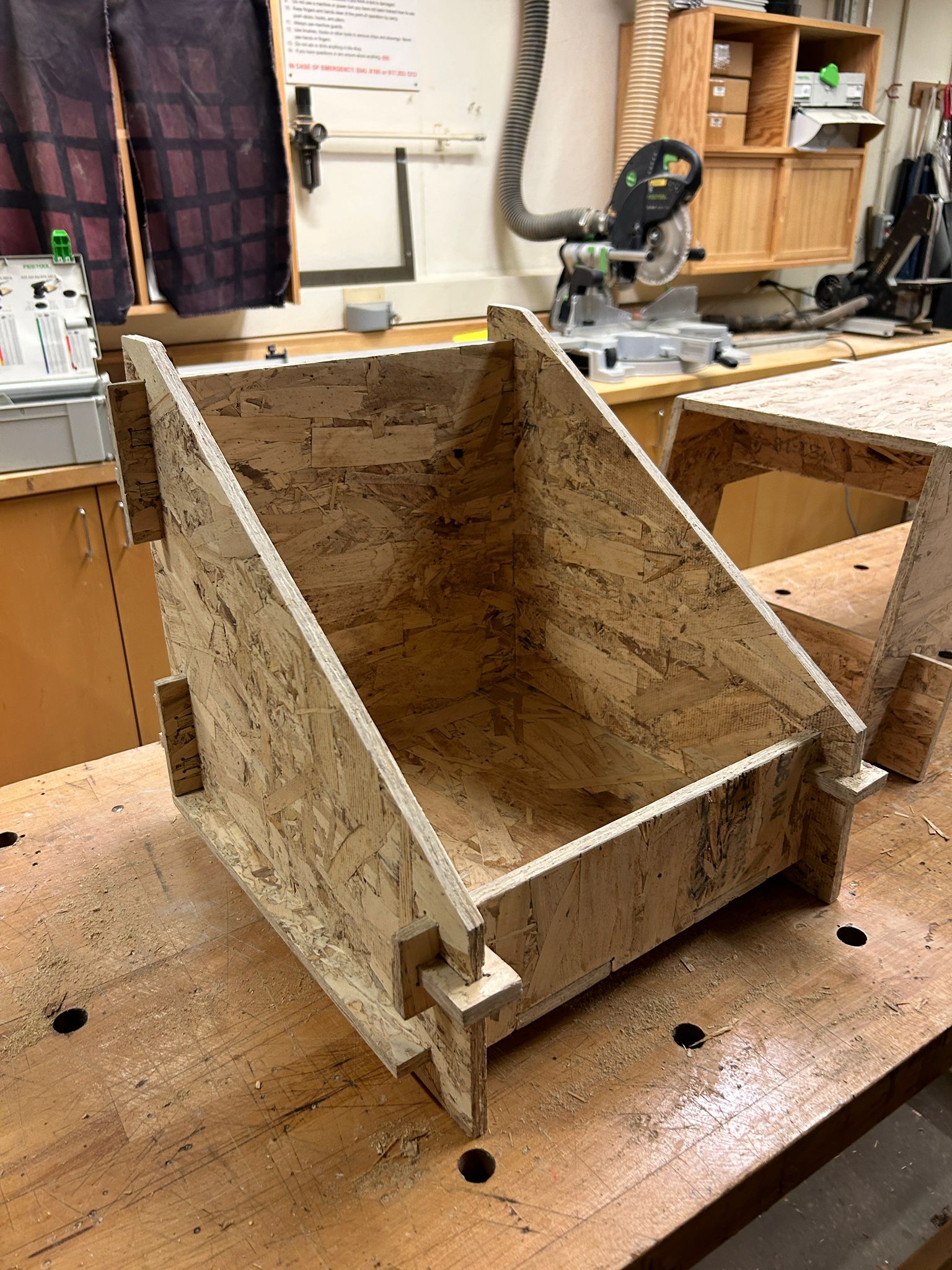
for the record box we had a different joinery idea.
we decided to have the individual panels notched and finger jointed together, having them protrude futher out, so a C-shaped piece would be able to slot in on either side, holding the piece in place and preventing it from sliding.
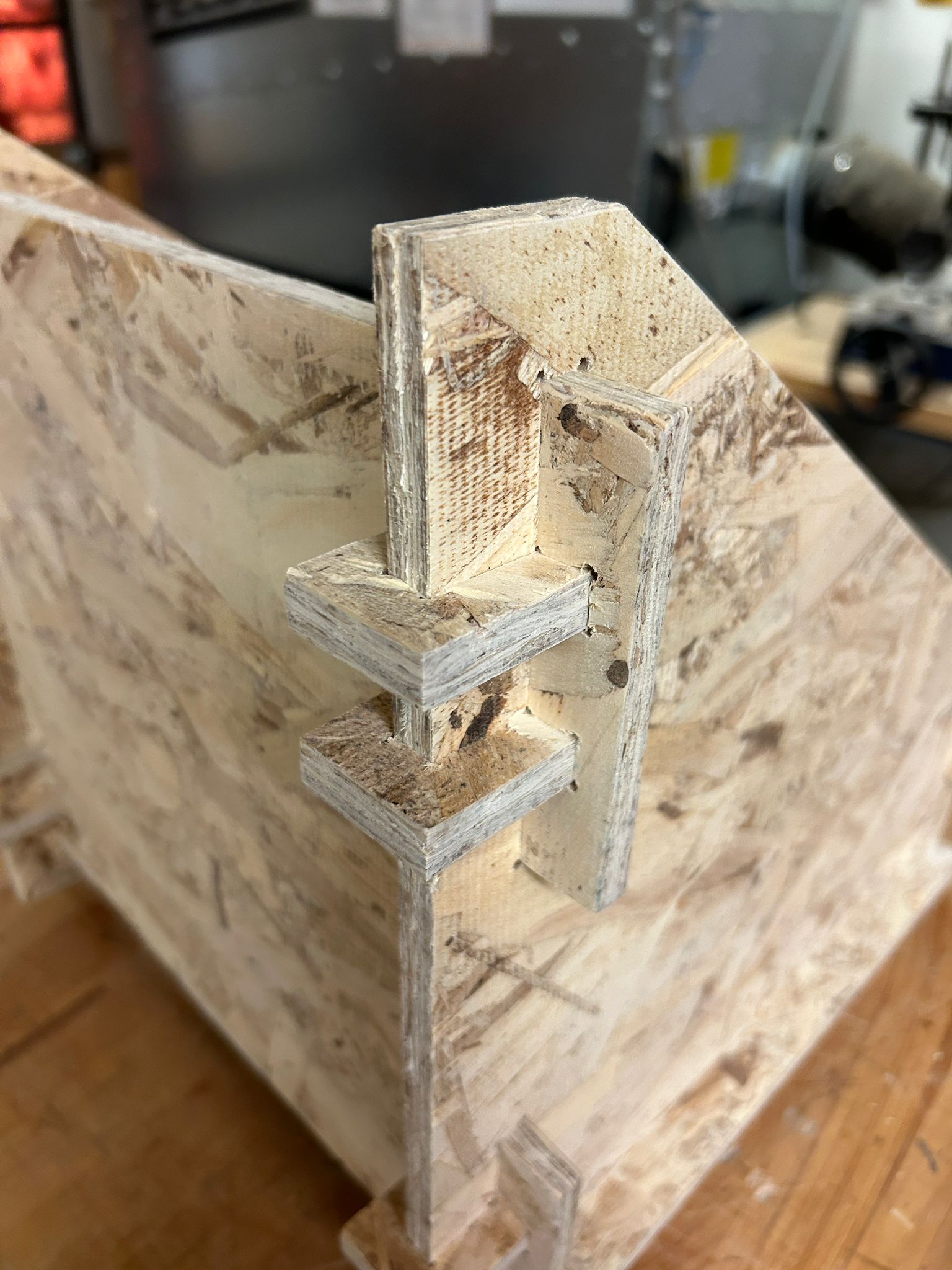
doing this twice per corner allows to make the joinery a lot smaller.
after these two things were done, it was time go get started with the chairpants. i wanted to make something that is a lot more achievable and easier to achieve before starting with this task.
it took a lot of convincing to get the arch shop staff to allow me to mill these parts on their mill. they did not believe me that any of these
pieces would come out alright or that my plan to put my weight on the end result would be possible using osb. the milling job took a really long time, because not only was it a lot of
different contour lines it needed to do, but each of the corners needed to be drilled out separately to ensure that another square piece would be able to slot in.
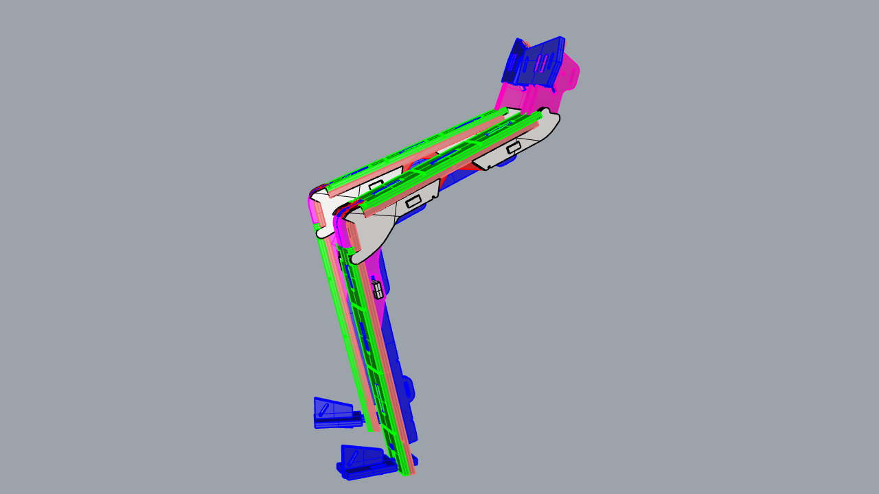
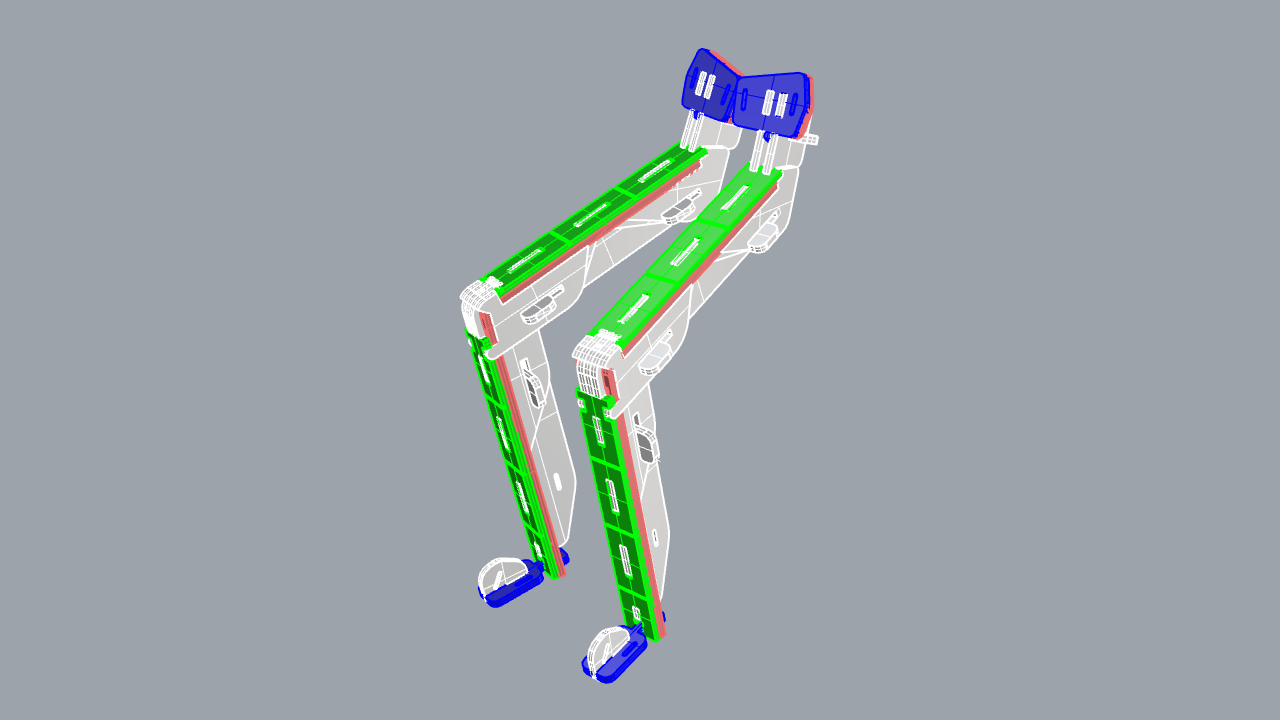
here is the 3d file of the construction:
chairpants rhino file
when milling a lot of small pieces it is a good idea to keep a thicker "onion skin" to hold the material in place. in this case, removing the onion skin was a lot more work, because of the small and curvy pieces with intricate notches and holes.
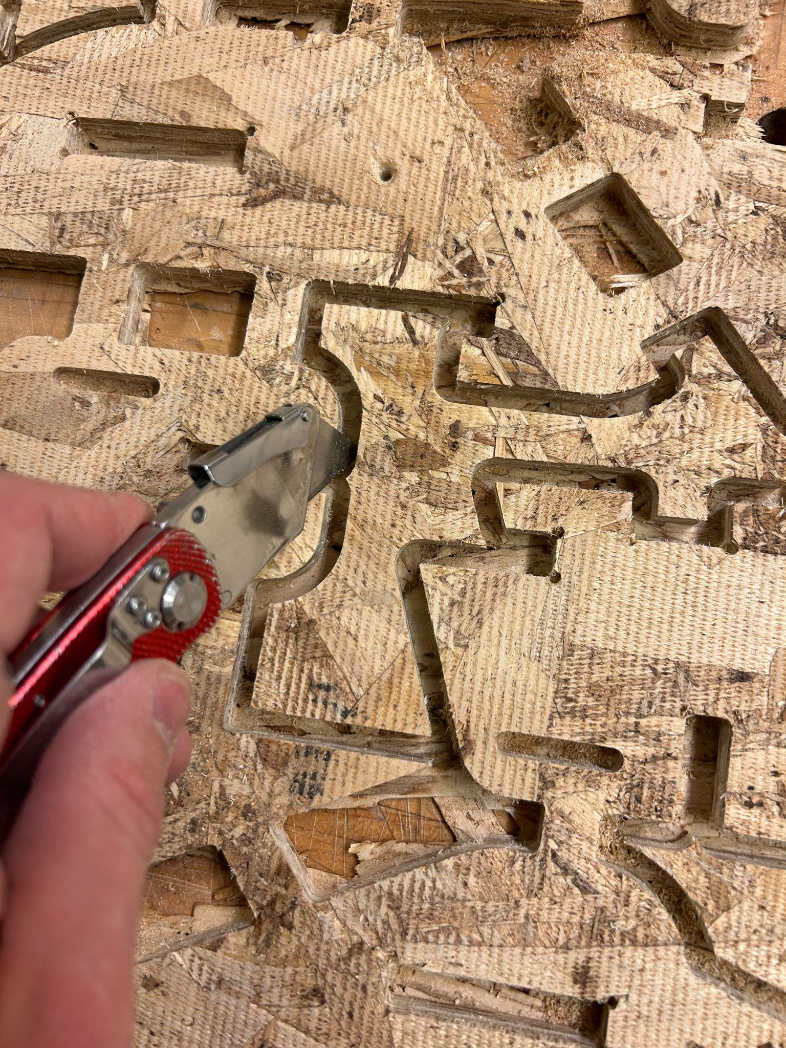
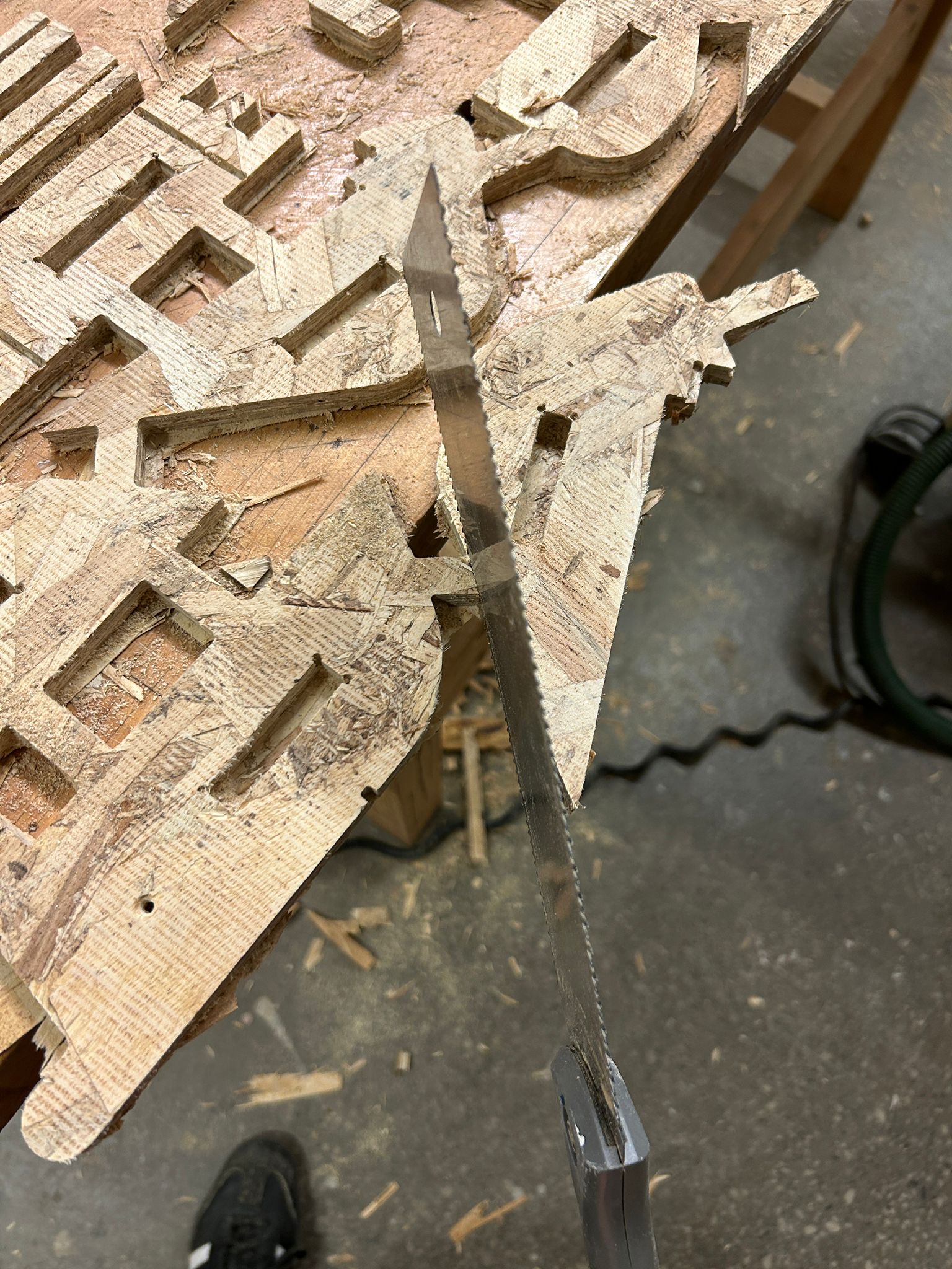
the easiest way to do it is to cut it all out with a knife, and cut the remaining tabs afterwards with a japanese handsaw, before sanding them smooth with a palm sander.
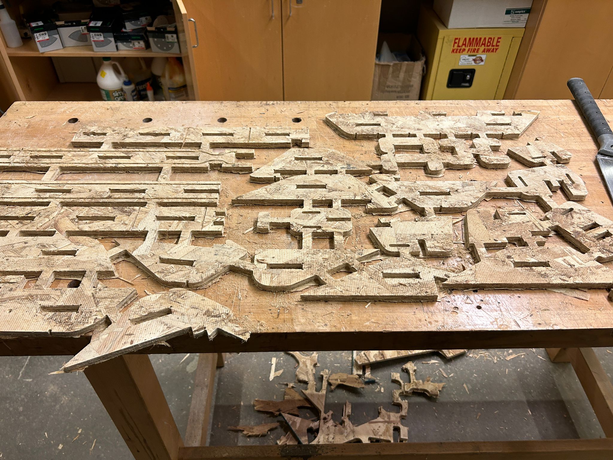
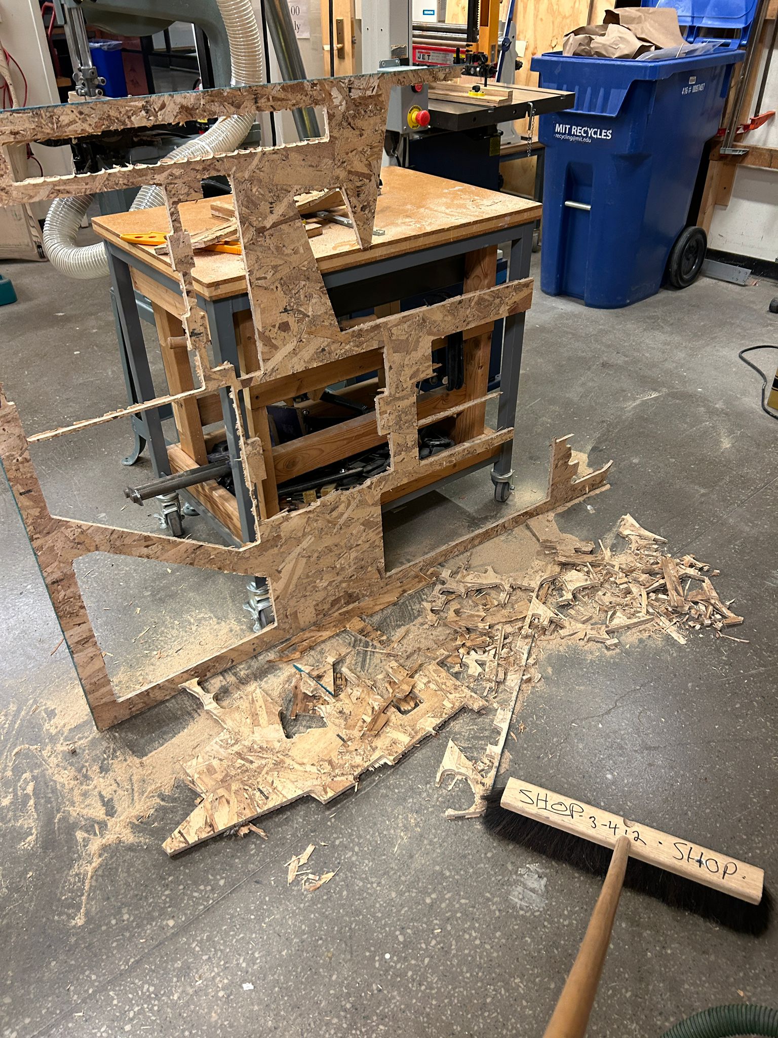
all the cutting, sawing, and sanding made a mess, and I was lucky to have had the shop pretty much to myself for the night. dont forget to clean up after yourself
i spare you with a lot of the assembly footage, since it is all pretty unspectacular, the basic principle is layering 2-4 sheets of osb together, and holding them together with a peg or c-shaped cross connector.
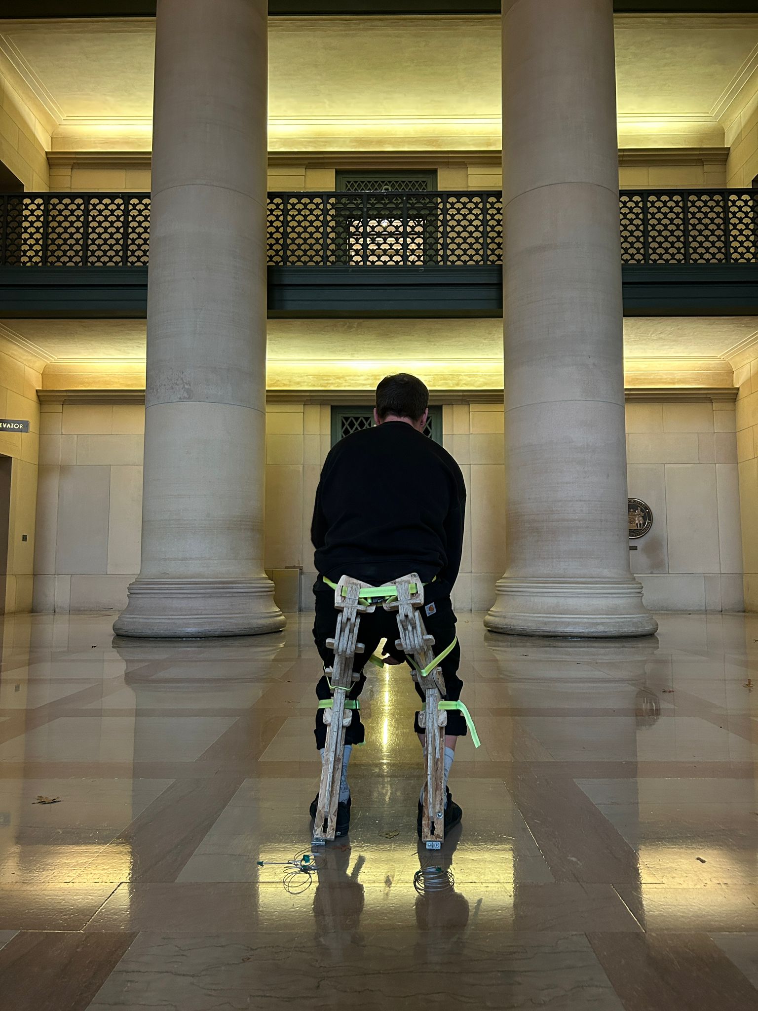
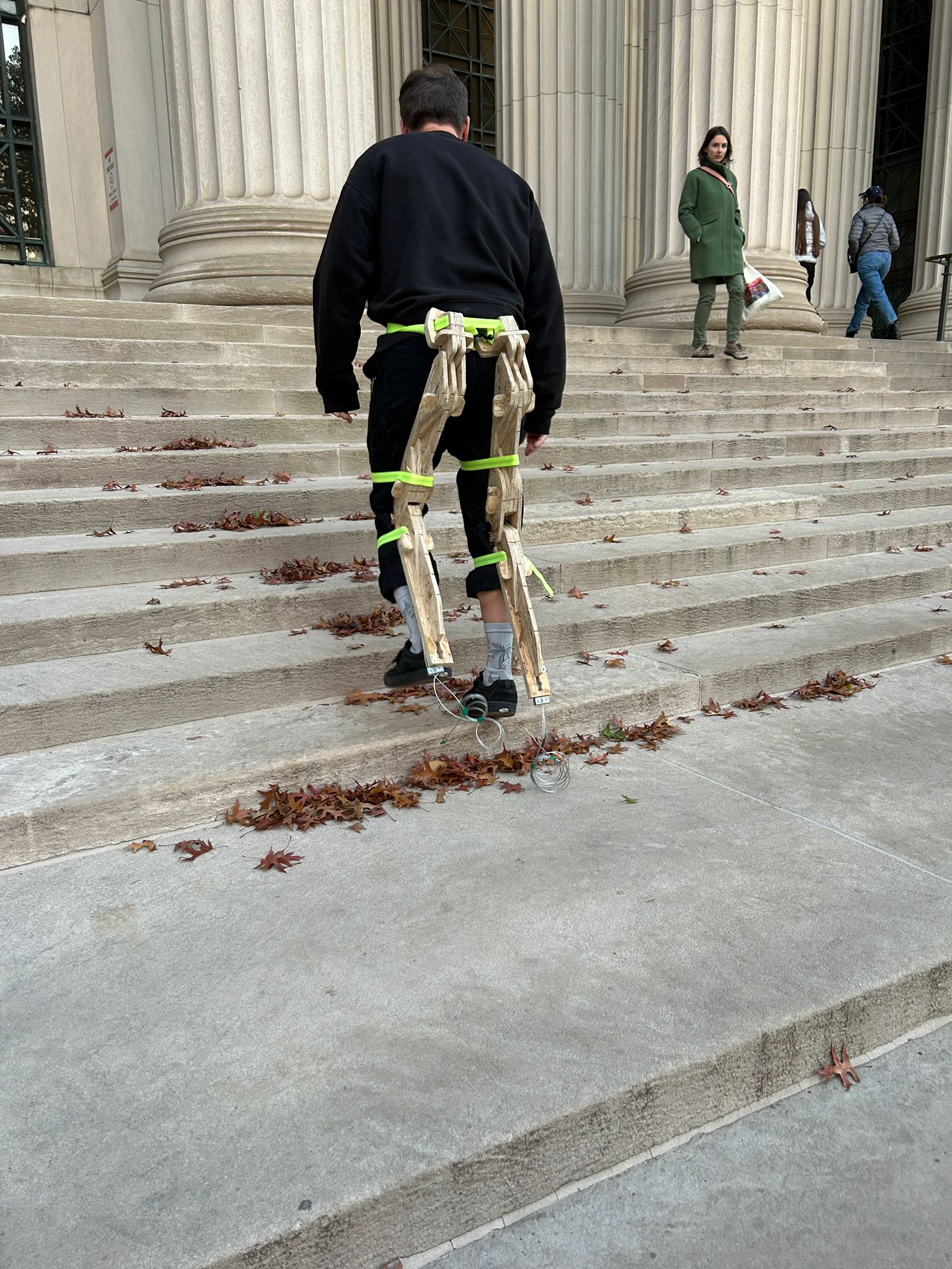
the inside of the chairpants reveals a channel that has a steel wire going all the way from the heel to the hip and back for each leg. this limits the maximal motion of the legs, since a stretched leg is shorter then a bend one.
additionally, i made sure that there is a physical limitation made with osb, but the main weight is held by the airplane cable, since the osb is so unpredictable in smaller sections, due to the inconsistent composition of wood chips.
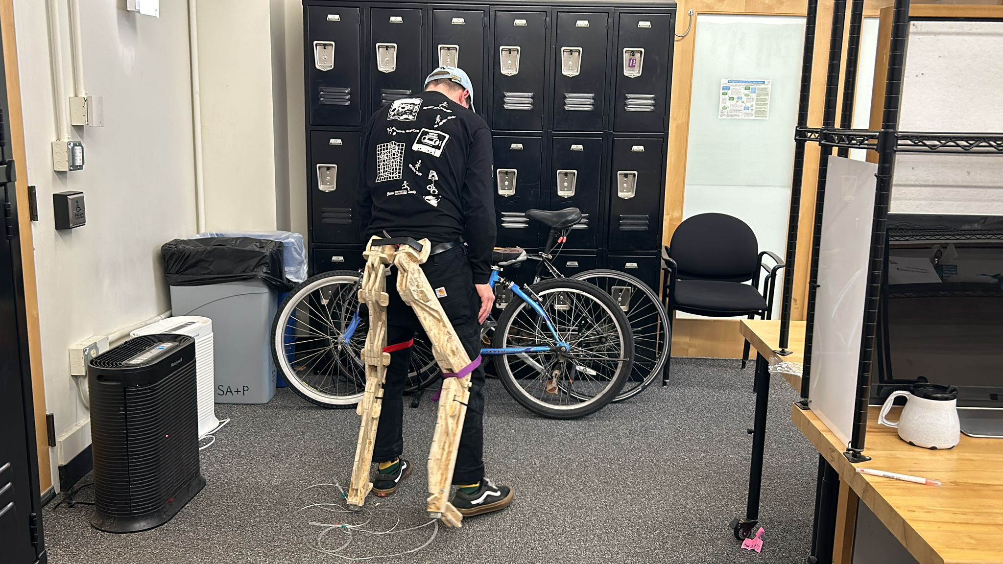
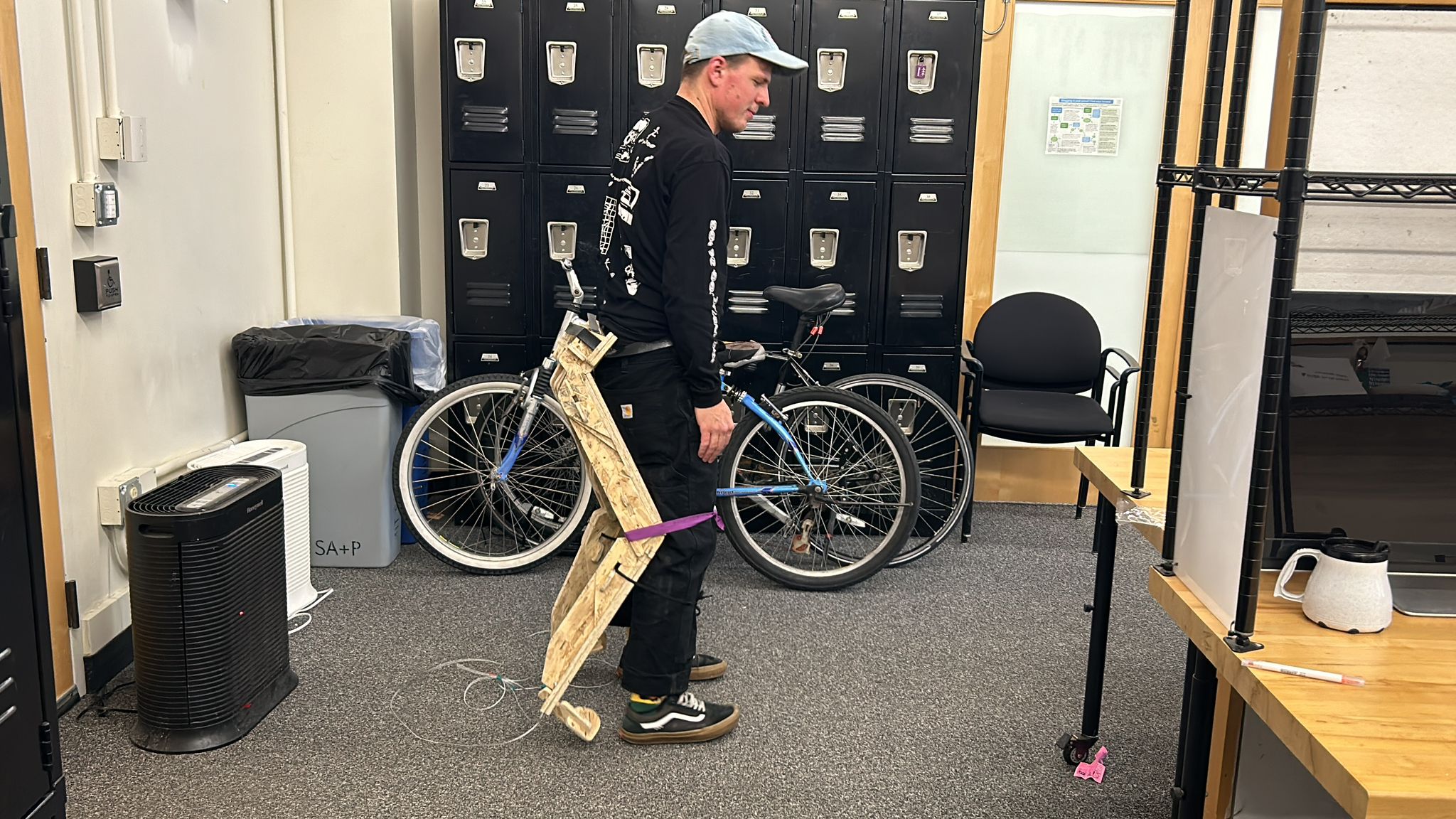
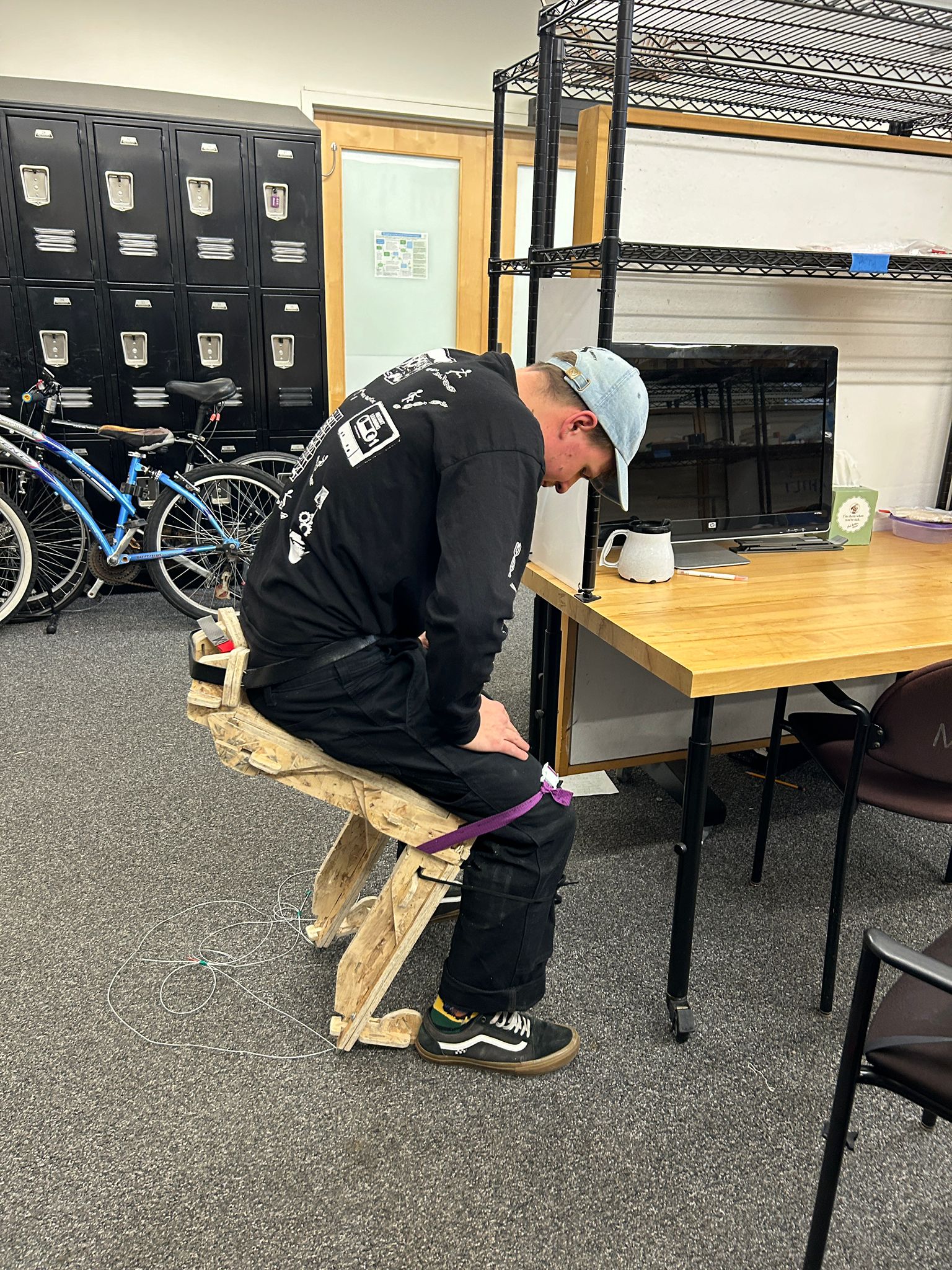
the first tests worked surprisingly well but I was still hesitant to put my full weight on them every time, simply because i had slits for actual belts and straps, but have not gotten to make them yet.
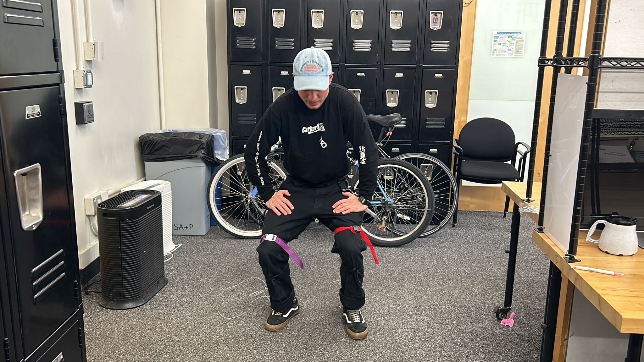
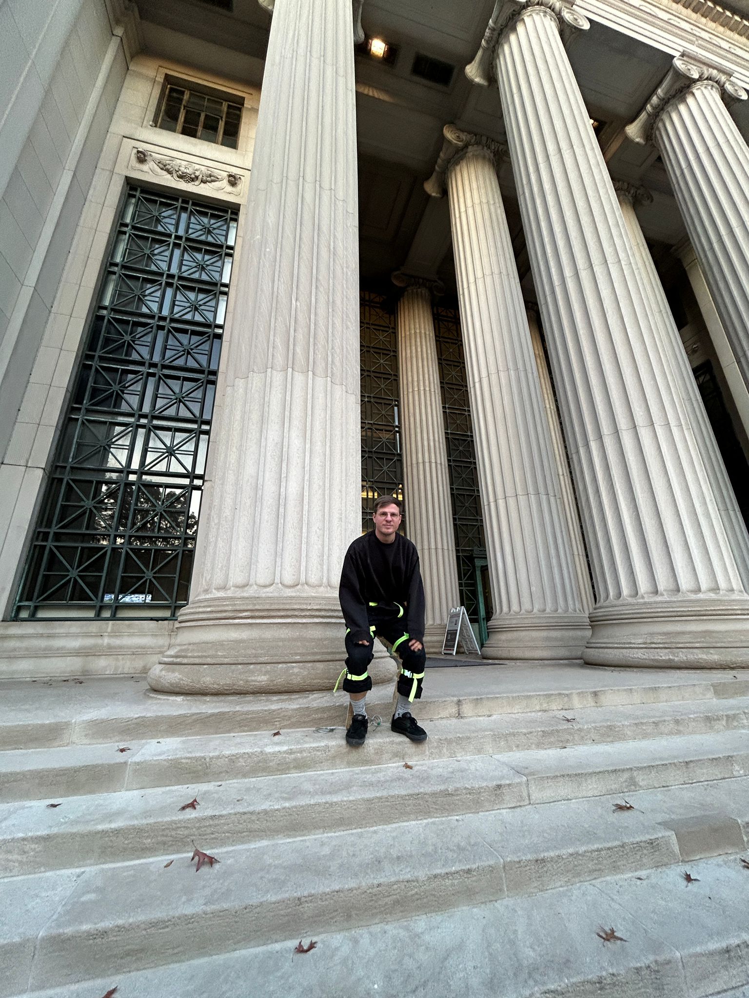
so a few days later it was time to make new straps and make some better photos of the osb-chairpants
i used backpack clips to allow adjustment and easy opening/closing of the straps
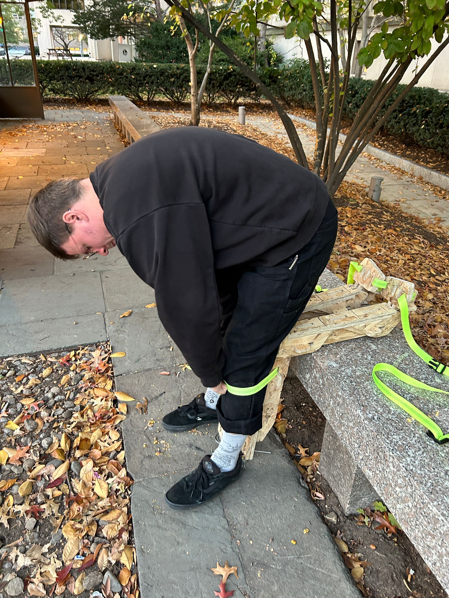
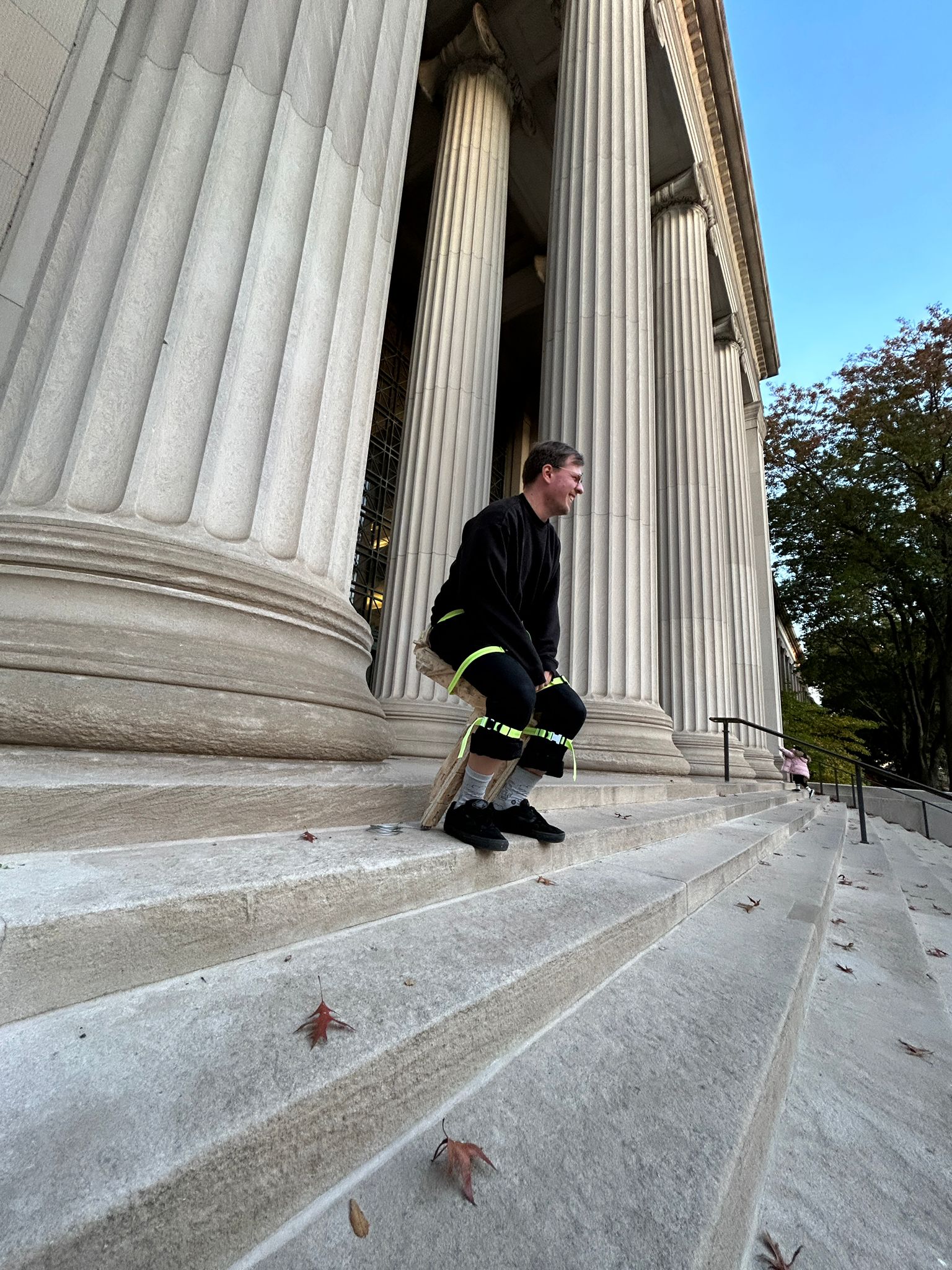
walking was fairly easy, so was walking up stairs (walking down was a lot harder because your heel was all over sudden 1-2" longer towards the back and would catch on steps when walking down)
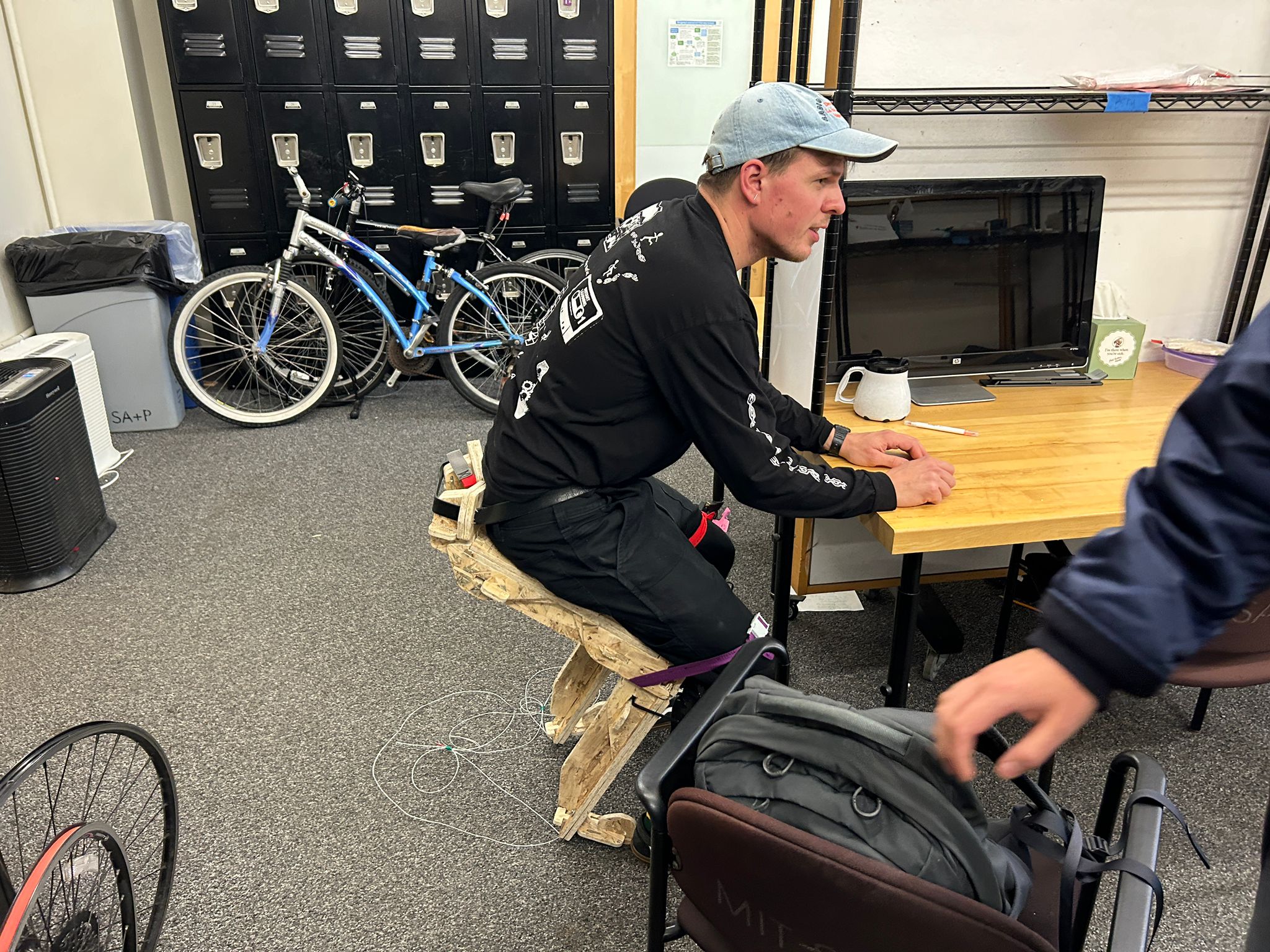
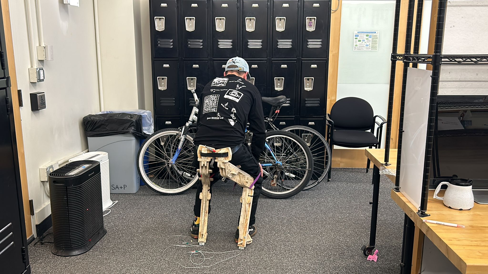
from here on out im just sittin'
...more sittin'
still here sitting'
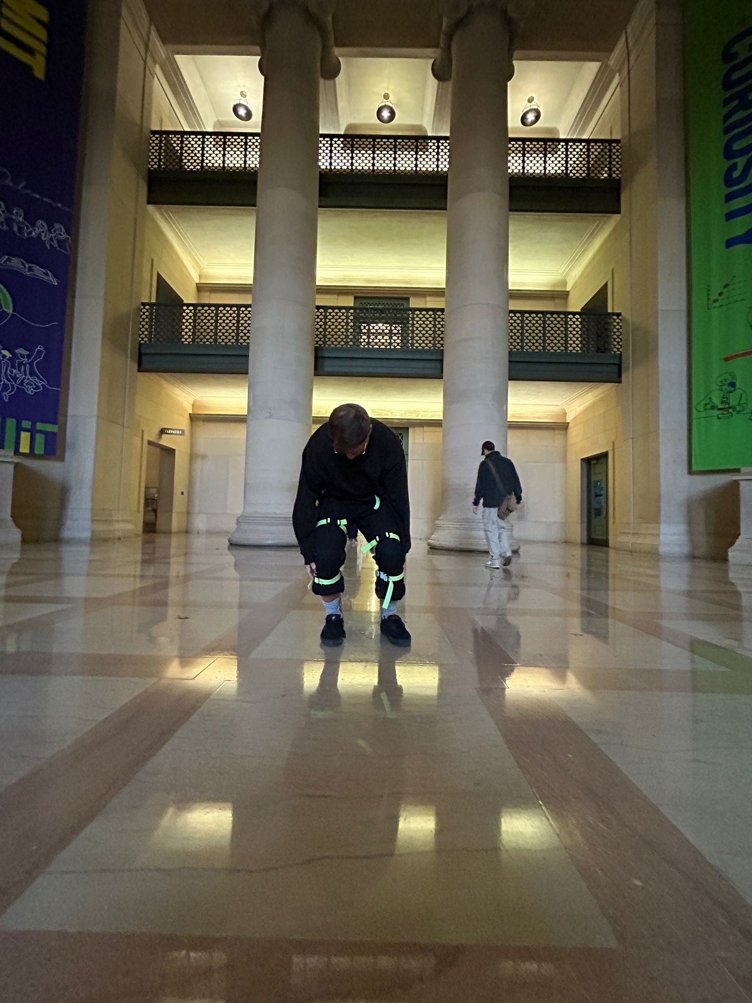
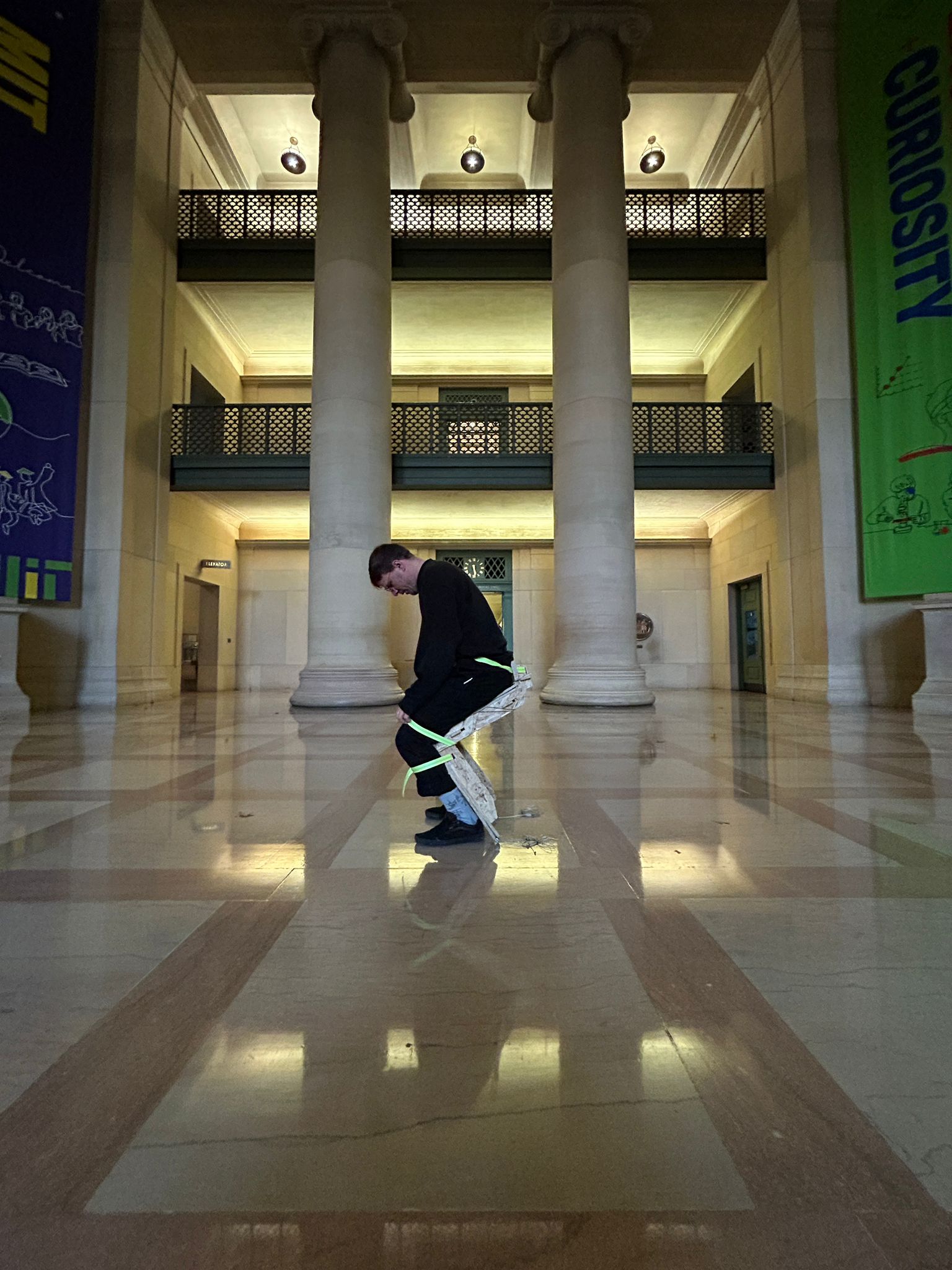
more sitting