| |
|
| |
 |
|
|
|
|
|
|
|
|
|
|
| |
HOW TO MAKE (ALMOST) ANYTHING MAS.863.12 |
|
|
|
|
|
PROJECTS |
ABOUT |
CONTACT |
|
|
| |
|
|
|
|
|
|
|
|
|
|
|
| |
| |
|
|
|
|
|
|
|
|
|
| |
 |
|
| |
|
|
| |
|
|
|
|
| FAB ISP (IN-SYSTEM PROGRAMMER) - week3 |
|
|
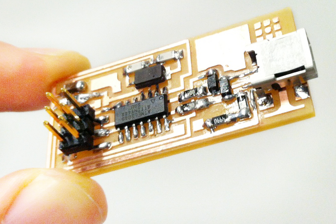
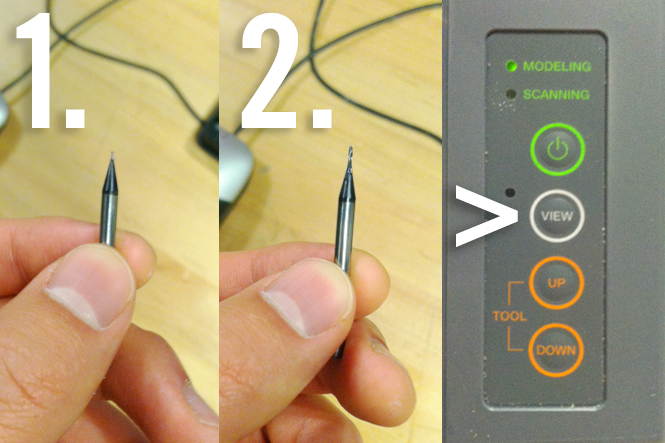
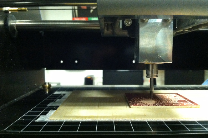
| This week we learned about PCB fabrication. The goal was to make the FabISP in-circuit programmer(created by David Mellis, updated by Neil Gershenfeld). Click here to see the original tutorial. I used Modela to mill the circuit board. First, I put double sided tape on the back of the board. Then I made sure that the board was taped down properly on Modela. While the Modela was in "view" mode, I zeroed the height of the end mill so that the tip would touch the board surface. There are two kinds of end mills that we use for making the board. Make sure you use the first one(1/64) for "mill traces" and the second end mill(1/32) for cutting the board. FYI, when using Fab Modules, we should have 2000 dpi traces PNG for creating the path. You can find more specific instructions here. Download PNG files from the following links: mill trace, board outline. |
|
|
| |
|
|
 |
|
| |
|
|
|
|
 |
|
| |
|
|
|
|
| Soldering The Board |
|
|
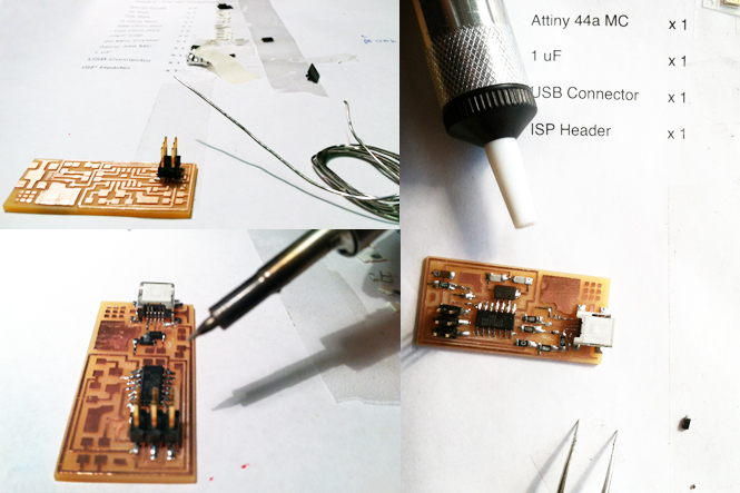
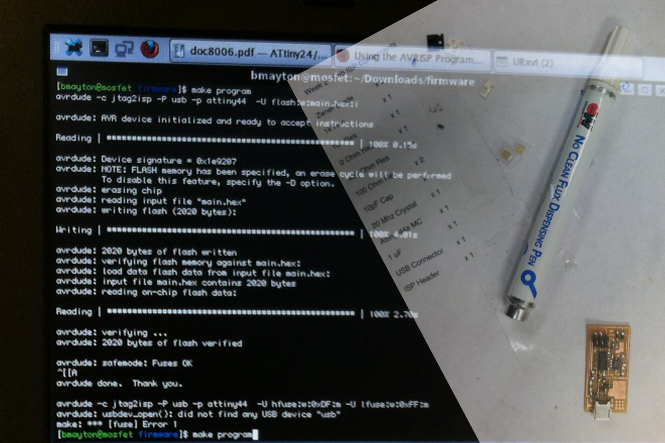
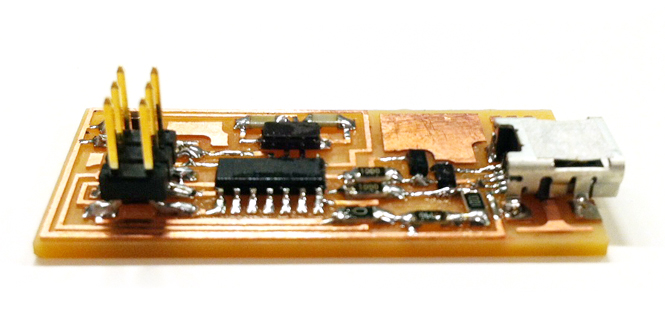
| After creating the board, I used the given diagram circuit to learn how to assemble the programmer. Later, I was able to obtain the list of the components from Rob the TA. Here is the component list. I put double sided tape on the printed list and attached the components next to the names. A few tips on soldering. If the board surface is not smooth, use steel ruler to clean up the bits. When the traces are narrow(e.g. USB connector) try to have a small amount of solder flow by rubbing the soldering iron on the surface. Solder from middle to the edge, from bottom to top. I had both the Zenor Diode(3.3V) in opposite direction and the USB connector had to be redone. I used vaccum desoldering tool to fix the problems. Brian Mayton the TA kindly helped me debug the board and we were able to program and run the board successfully after several attempts. To program the FabISP, you may have to download a firmware for mac from here. |
| |
|
|
 |
|
| |
|
|
|
|
 |
|
| |
|
|
|
|
| Result |
|
| I learned a few new things about soldering and debugging the board. The transparent liquid that you see as you solder is called flux. The purpose of flux is to make the soldering easier. Sometimes when the solder melts in an undesirable way, you may want to see if you heated up too much that the flux has evaporated. If everything seems to look right but needs debugging, sometimes the best solution is to first, apply flux on the solder using clean-flux-dispensing pen, then apply heat using the soldering iron on each and every soldered parts. Hopefully that would fix your problem. |
|
| |
|
|
|
 |
|
| |
|
|
|
|
 |
|
 |
|
 |
| |
|
|
|
|
FINAL PROJECT PROPOSAL.
My ideas for the final project- week1
|
|
PRESS-FIT CONSTRUCTION KIT.
Learn how to make something using vinyl cutter and laser cutter - week2
|
|
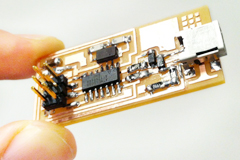
FAB ISP (IN-SYSTEM PROGRAMMER)
Learn how to make a custom PCB - week3 |
| |
|
|
|
|
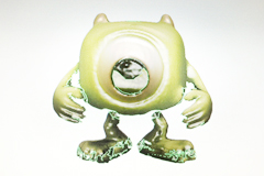
3D SCANNING AND PRINTING.
Learn how to make 3D printed model - week4 |
|
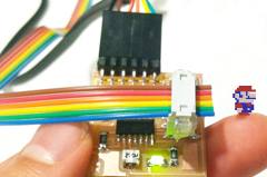
ELECTRONICS DESIGN.
Learn how to redraw the echo hello-world board - week5 |
|
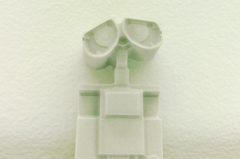
MOLDING AND CASTING.
Learn how to design a 3D mold, machine it, and cast parts from it - week6 |
| |
|
|
|
|
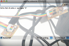
EMBEDDED PROGRAMMING.
Learn how to program a custom board to do something - week7 |
|
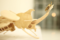
MAKE SOMETHING BIG.
Learn how to make SOMETHING BIG through computer-controlled machining- week8 |
|
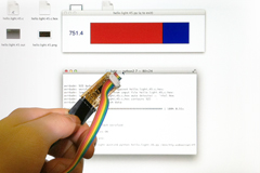
INPUT DEVICES.
Learn how to add sensor to a microcontroller board and read it - week9 |
| |
|
|
|
|
COMPOSITES.
Learn how to assemble a 3D mold, and lay up a fiber composite part in it - week10 |
|
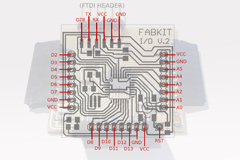
OUTPUT DEVICES.
Learn how to add an output device to a microcontroller board and program it to do something - week11 |
|
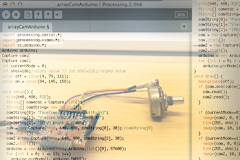
INTERFACE AND APPLICATION PROGRAMMING.
Learn how to write an application that interfaces with an input &/or output device - week12 |
| |
|
|
|
|
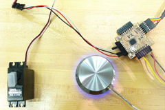
NETWORKING AND COMMUNICATIONS.
Learn how to build a wired &/or wireless network with at least two nodes - week13 |
|
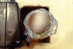
MECHANICAL/MACHINE DESIGN.
Learn how to design or modify a machine and automate the machine - week14 |
|
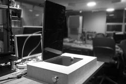
FINAL PROJECT.
My final project for How To Make (almost) Anything - week15, 16 |
| |
|
|
|
|

MAS.863
Learn about the How To Make (almost) Anything course at MIT |
|
|
|
|
| |
|
|
|
|
 |
|
 |
|
 |
| |
|
Copyright © 2012 by AUSTIN S. LEE |
|
|
| |
|
|
|
|
| |
|
| |
|
|
|


