I decided to make a (semi) Charlieplexed LED array with RGB lights. This continued off my project a few weeks ago with 4 RGB LEDs Charlieplexed.
I decided on a 4×4 array for manageability. 16 RGB LEDs is 48 LEDs (if we ignore the shared anode constraint), which we could drive with 8 pins using Charlieplexing (8*7 > 48). The layout and crossings for that would be difficult (see Neil’s examples for workable solutions). I decided to clone my 4 LED multiplexing design, making each row separate. This uses 4*4 IO pins, but requires no crossing. After laying it all out, I realized I could save a few more pins without crosses by sharing adjacent rails between rows and looping a few row lines down to the next row. Next time…
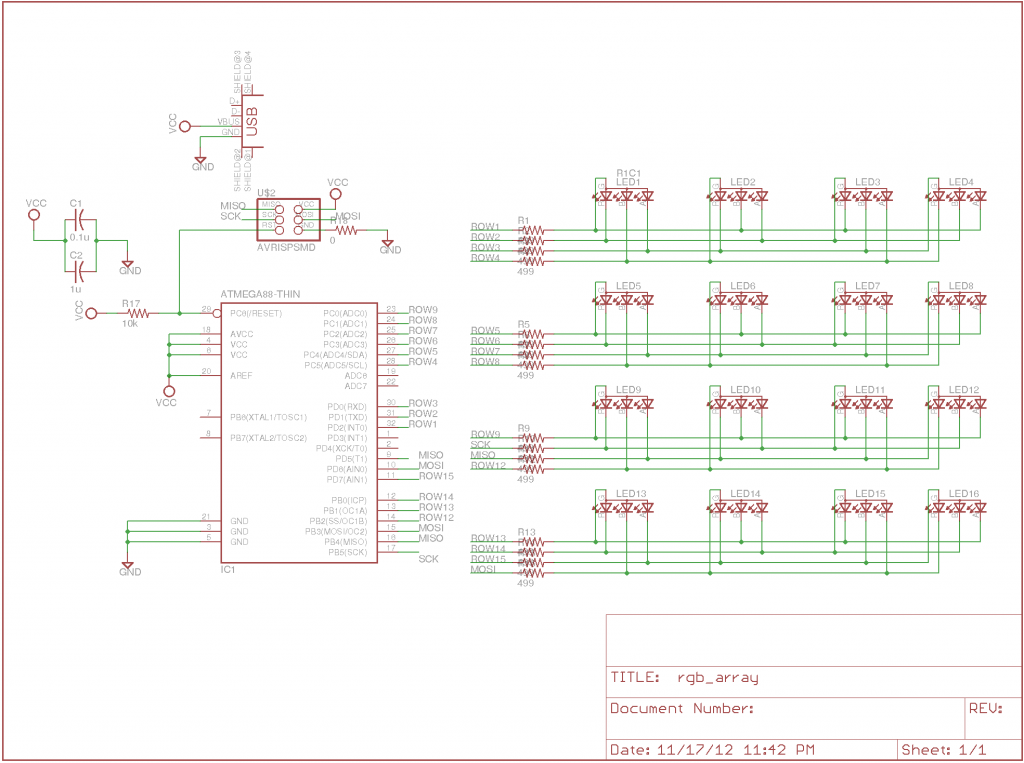
I did the layout in Eagle. It’s sometimes tedious, but I like the control it offers and the visual workflow agrees better with how I think about layout right now. Here’s the schematic:
I put a mini-USB connector for power and not much else. I used an ATmega328 to get enough IO pins. I thought about leaving space for a resonator, breaking out unused pins, and bringing USB data to the MCU, but the layout was too tight.
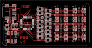
Here’s the circuit laid out:
As before, I had to send 2 traces underneath each RGB LED to work. The layout works because each LED is rotated 180 degrees. I send traces under the MCU by coming in diagonally from the corners. I sent traces under the mini-USB connector, which I’ll explain soon. I laid out the left and right sides manually, then used the auto-router to connect the MCU to the resistor array. I used a fine grid and told it to prefer diagonal traces.
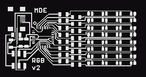
Here are the trace and board files for the Modela:
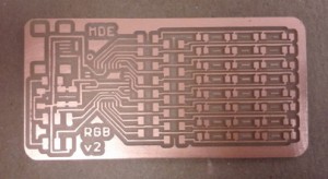
I decreased the tool width in the fab modules until all the traces were cleanly separated in the path. For the first try milling, I set the cut depth too deep and some of the small traces peeled off:
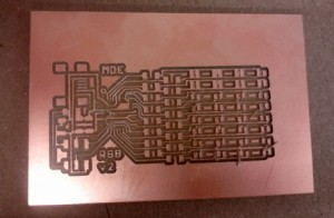
I went back to the default depth and everything was fine. Some traces are very thin, but seem sturdy and tested fine:
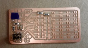
I cut a piece of vinyl to cover the traces going under the mini-USB connector. I didn’t want the connector shell to short out these traces.
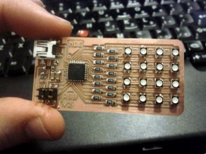
Completely stuffed board:
I wrote some code to run through colors randomly. It revealed that I had a bad solder joint on the green pin of one LED.
I made it cycle through the letters M I T. Here’s the code and makefile. You program it the usual way (I use my FabISP to power the board):
sudo make -f matt_rgb_array.make program-usbtiny
Here’s a video of the flashing message:
Update: Eagle files and code are here. I used the class fab.lbr and the SparkFun Eagle libraries. I still need to make cooler patterns and messages for the board…

