Final project progress
I thought of several final project ideas over the course of the semester and have settled on a useful (to me) one: an internet-enabled automatic pet feeder.
Existing work
There are a lot of commercial options that operate solely with timers (check out Amazon). There are some do-it-yourself versions that relied on 3d printing, such as these two.
Design and materials
Inspired by the MTM Snap, I’m planning to build a snap-fit housing out of HDPE. I’ll have a 3d printed augur screw within a plastic tube to transport the food from the upper storage bin into the feeding bowl. A stepper motor will drive the screw, and the electronics will be in the bottom part of the housing.
Rough bill of materials
- HDPE, two 15″x20″x0.5″ sheets, $30, from Amazon
- Clear polycarbonate pipe, 2′, 1.5″ ID, $12, from Amazon
- Roving Networks RN-XV wifi module, $35, from Sparkfun
- 3d printed augur screw from Arch fablab
- 7V stepper motor and assorted electronics from the fab inventory
Construction plan
The screw is hopefully being printed now. I’ll finish the housing design in the next two days and cut out the pieces on the Shopbot early in the weekend.
Electronics plan
I will lay out a PCB with MOSFETs to drive the stepper, holes for the wifi module, and connections to any input devices I may add. I’ll put an ATmega328 on the board and use the hardware UART to talk to the RN-XV. I plan to program it with Arduno since I’ve grown to like the extensive easy-to-use libraries. The last thing is to code up a basic server for the module to talk to and determine its feeding schedule.
Schedule
The plan is to be done with all design work during the week and spend the weekend doing the fabrication. The late weekend or Monday will be spent on software.
Evaluation
If the machine can reliably dispense food on a schedule, I will feel that it’s successful. Any input or tracking from the machine back to the web server would be a bonus.
Current status
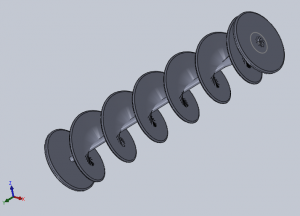
I spent a lot of time making the augur screw. I cut an indentation for the gear on the stepper motor to allow simple coupling to the drive shaft. Since I’m (still?) a total CAD beginner, this took me a really long time to do in SolidWorks.
I used this Solidworks gear calculator and consulted a few instructional sites for how to make helical shapes, like this one.
Here’s the final model:
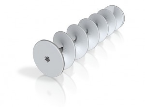
And rendered by Shapeways (the 6″x1.5″x1.5″ part priced out at $23 from them):
I had a lot of trouble getting the mesh watertight, since I was accidentally using a few open surfaces instead of closed solids. I used the program AccuTrans3D to check for watertightness, and then found the SolidWorks “Check” tool which actually identify the source of the problems. As usual, I exported to STL for printing.
I made a paper mockup for the housing design. The dimensions are off, but the basic idea is what I’d like to do:
Questions
Food safety of ABS? Importance of FDA approval?


