
Designed board: Charlieplexed RGB LEDs
I spent some time working with my RGB LED board from two weeks ago. It uses 4 IO pins to drive 4 RGB LEDs (so 12 total) with software PWM for color mixing.

You can see the design files on the original page. You can watch the video of the interactive color mixing here:
My C code for the board is here and the makefile is here (more programming details are available on the original page).
Evolved board: Powering target boards with the FabISP
After some research online, I learned that ISPs sometimes power target boards. This simplifies things when you don’t want to hook up another cable or don’t have an FTDI cable around. Note: you should be careful about driving power-hungry circuits from 5V from USB.
The second solder jumper in the FabISP design disconnects the (USB) input voltage from the VCC programming pin. It’s SJ2 in the original schematic:

It’s perfectly placed for soldering a surface-mount slide switch to span the gap (bottom edge below). I soldered all three pins for stability, but the left two are to the same trace.

The green piece of vinyl marks the powered state, while the opposite direction is the (original) unpowered state. I used the powered state to program my RGB LED board and Fabduino without additional cables.
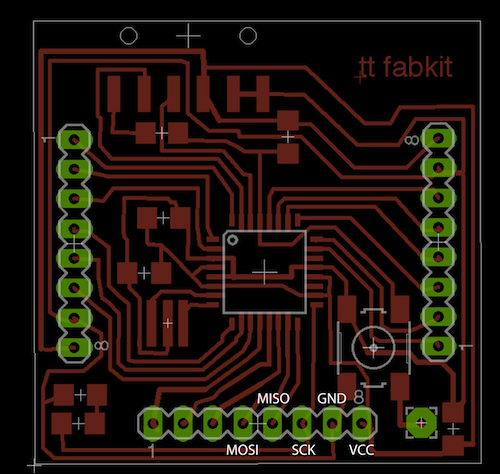
Pre-designed board: Fabduino
With an eye towards future weeks, I decided to make the Fabduino. I followed the original instructions as well as Tiffany Tseng’s tutorial. The original design (with Arduino-labeled pins) is copied here:

I milled almost the original files, but the header holes were too large when using the “cut board” default settings. I don’t know if this is a settings issue or missed instructions on my part. Additionally, the endmill loosened and scratched up the interior traces during this cut. Sad board:

I remilled the board and used a new hole file that shrunk the diameters to 50% of the original size. Here’s the new hole file:

I set the toolpath width to 0.005 mm and stayed with the 1/64″ endmill to keep the holes small. This worked well and gave press-fit tolerances for the female headers. I only had enough headers available for 7 of the 8 pins on the outer edges.

Through all this, I doubled the z depth of the “mill traces” default. This has been necessary for my past several boards, and I’m not sure why.
I stuffed the board following the specs, substituting in an ATmega328 for more memory (it’s pin-compatible with the 168 from the original schematic). I had to replace the 1uF cap (none in the lab) with a 10uF, but I don’t think matters much since it’s just one of three smoothing caps in the circuit.
The ATmega has really small pins, so the “flood then wick” strategy from the mini USB pins of the FabISP really helped. The pins from the female headers were pretty picky about getting good connections: I had to give them a lot of solder and test several times to make sure the connections made it into the board.
Stuffed board (notice I haven’t put a resonator on the board):

I made a bootleg connector to take the 2×3 ISP signals into the appropriate pins on the bottom rail of the Fabduino. I referenced Tiffany’s page for pinouts, her image is here:
The reset pin has to be held to the round pad in the bottom right corner (I didn’t give it a header).
I ran into a few hurdles programming the board. Avrdude only knows the m328p (pico-power version), which has a different device signature. I edited /etc/avrdude.conf by copying the m328p configuration section to a new m328 entry. The only changed lines are:
id = "m328";
desc = "ATMEGA328";
signature = 0x1e 0x95 0x14;
To get Arduino working, I had to add a new boards.txt file in the right place (based on the original Fabduino instructions). On Linux, I run the Arduino IDE as root and so I made a new file as ~root/sketchbook/hardware/fabduino/boards.txt (also see this page).
I added these lines (edited from the original, since I’m using a 328 instead of a 168):
fabduino2.name=Fabkit/Fabduino w/ ATmega328 (internal clock)

fabduino2.upload.protocol=stk500
fabduino2.upload.maximum_size=30720
fabduino2.upload.speed=57600

fabduino2.bootloader.low_fuses=0xe2
fabduino2.bootloader.high_fuses=0xdd
fabduino2.bootloader.extended_fuses=0x00
fabduino2.bootloader.path=arduino:atmega
fabduino2.bootloader.file=ATmegaBOOT_168_atmega328_pro_8MHz.hex
fabduino2.bootloader.unlock_bits=0x3F
fabduino2.bootloader.lock_bits=0x0F

fabduino2.build.mcu=atmega328
fabduino2.build.f_cpu=8000000L
fabduino2.build.core=arduino:arduino
fabduino2.build.variant=arduino:standard
In Arduino 1.0.1, I set the programmer to USBtinyISP and the board to my new entry. I connected my FabISP to the Fabduino, with USB power enabled, and held the reset pin to the correct pad on the Fabduino.

I successfully burned the bootloader. I opened up the blink example sketch and made a simple change to turn the LED on for 1, 2, 3, …, up to 10 seconds (in order, looping). I could “Upload using programmer” successfully, but plain “Upload” (via FTDI to the top header) didn’t work. I haven’t had time to debug that yet, though.
Update: a better fix to the ATmega328 problem is to install the latest Subversion revision of avrdude. On my Ubuntu machine:
sudo apt-get install libelf-dev libusb-dev libftdi-dev libusb-1.0-0-dev flex

svn co svn://svn.sv.gnu.org/avrdude/trunk

cd trunk/avrdude
./bootstrap
./configure
make
sudo make install
cp avrdude.conf /etc/avrdude.conf
You need to let Arduino use the system avrdude installation, instead of the prepackaged one. Delete the hardware/tools folder, for example:
rm -r arduino-1.0.1/hardware/tools/
Programming via the FTDI cable still doesn’t work (stk500 protocol error saying the programmer isn’t responding). I think I may have a bad connection at the header: will test and update later. For now, programming with the FabISP works fine.