Electronics
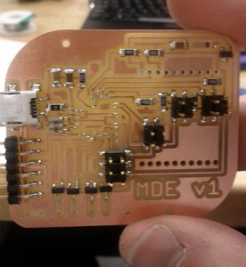
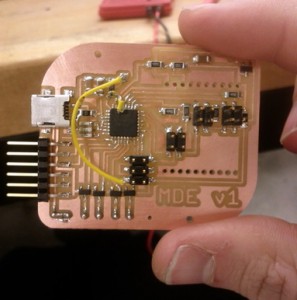
I designed a board with all the peripherals I’d need. It has two 2×2 headers for inputs, one 2×2 header for serial communication, and a reversed through-hole socket for the RN-XV wifi module (similar to my second try at an XBee-FTDI board).
I put on a resonator so I wouldn’t have to worry about clock inaccuracies, an FTDI header for debugging, and a mini-USB connector for power. The stepper motor is on the border of the power spec for laptops, but I plan to power it from a wall wart.
The stepper motor is driven by four NMOSFETs (like in Neil’s design), connected with screw terminals on the opposite side of the board.
Bad endmill leads to peeling traces underneath the mega328 leads to a Frankenboard. But it works…
Design
I sketched up the design in Solidworks, exported to DXF, and prepared the image for toolpathing in Inkscape and the GIMP. I made the Shopbot toolpaths with the fab modules.
Design files to come!
Structure
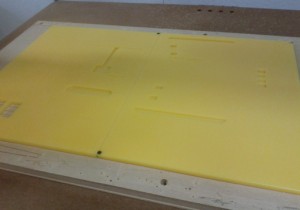
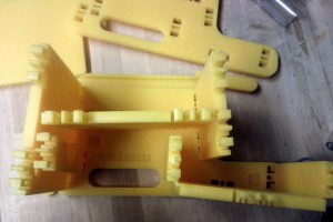
Fun on the Shopbot:
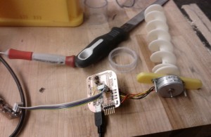
3d printed screw (designed last week) mounted onto stepper motor:
The tube for the screw is a clear polycarbonate pipe from Amazon Supply. I manually machined it and added holes for the food to enter and exit.
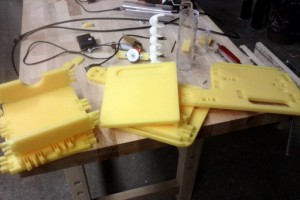
Partially assembled. Notice semicircular cutouts for the tube.
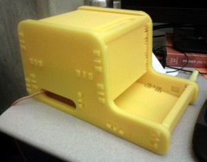
Final product!
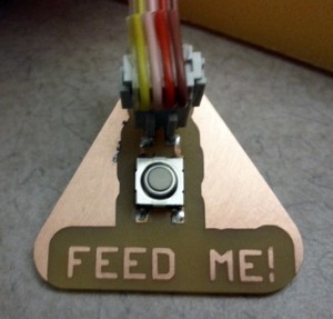
The Wifi module didn’t get here in time, so I improvised with a lower-tech solution to active it:

