Eagle installation on Ubuntu
Ubuntu software sources only have Eagle 5.12 (in Ubuntu 12.04.1). Get the latest version of Eagle (6.2) from their website.
Install the version of libpng that it requires, following instructions here. The key step is forcing the library to compile in 32-bit mode (not default if you’re on a 64-bit system).
./configure --prefix=`pwd` CFLAGS=-m32
If you get an error about zlib, you might need the 32-bit zlib headers on your machine. Run:
sudo apt-get install zlib1g-dev:i386
For Eagle, you probably want the class component library here. The SparkFun library is also useful.
Circuit design
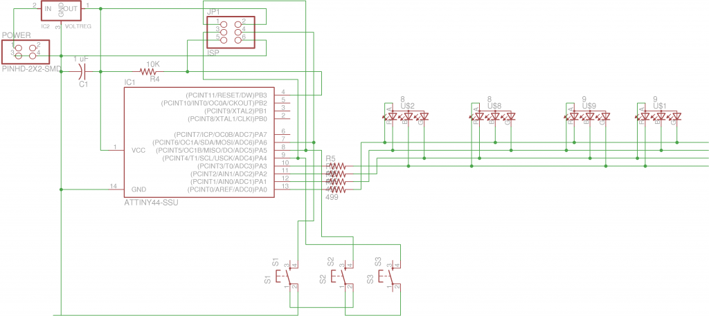
I looked at several circuits from future lectures to figure out how to integrate LEDs and buttons with the Tiny44. This included the hello.button board, the hello.RGB board, and the hello.array board.
I wanted to experiment with RGB LEDs and building a small array seemed like good layout practice. My original goals were more ambitious and I wanted to use more IO pins, so I left off the crystal and serial header. My final design has some spare pins, but I didn’t add back these extra components.
The design principles are mostly taken from other boards: a 10K pull-up resistor for the reset pin, a smoothing capacitor across the voltage source, and switches coming from ground into input pins. I shared some pins with the ISP header, since my brief research said that was okay (except for the reset pin).
The RGB mini-array is weakly Charlieplexed… I wanted to test out color-mixing, so I wanted to be able to send voltage to the color-specific cathodes of a particular LED at the same time (anodes are shared). So I have four pins controlling 12 colors: each pin is an anode for one LED and a cathode for one color of the other three.
I ran Eagle’s electrical rule check to make sure everything looked good. Naming nets “VCC” and “GND” will help Eagle know if the correct IC pins are connected.
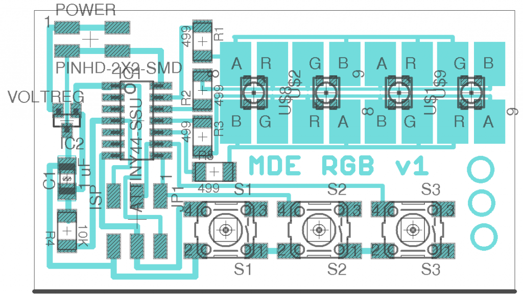
Circuit layout
The layout was pretty straightforward except for the LED array. My 4-rail design works well without crossovers if you flip two LEDs. This way, only two rails need to go under the row of LEDs (a difficult routing).
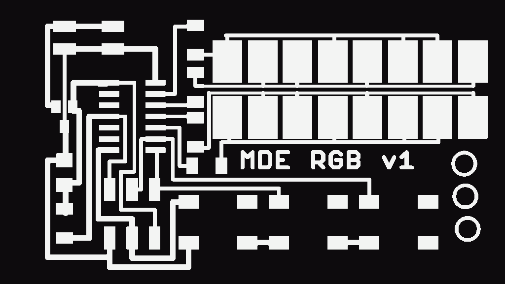
It’s less exciting, but you can see the exterior too:
The huge pads for the LEDs are from the fab library. The smaller ones (labeled “old”) have two pins swapped, plus I think these look kind of interesting… so I stuck with them.
I played with Eagle’s autoroute without much success. Since there’s so much freedom in placing and rotating the components, it doesn’t help out a ton. I ended up basing the left half mostly on some of Neil’s boards and the right half by hand. I used 24 mil traces for most traces, but 16 mil traces coming out of the buttons and in tight areas under the Tiny44. I had to use 12 mil traces under the row of LEDs in order to satisfy Eagle.
I added a label to the board and some circles for fun. In the future I’ll put some markings to orient the various connectors.
Fabrication
I had trouble getting my PNGs (exported from Eagle at 1000 dpi) recognized by the fab modules. I solved the problem by resaving the PNGs in the GIMP, resaving that in JPG, and resaving that in PNG (even though that sounds strange).
For whatever reason, the Modela was less happy than two weeks ago. My first pass left the top half of the board poorly cut and completely ignored my small under-LED traces. The lesson is to look more closely at the path output.
I fixed it by dropping the z depth in the fab modules and lowering the offset until the path looked more reasonable. I thought about working with a smaller end mill, but surprisingly enough the second pass worked. The under-LED traces are pretty tiny, but they look strong and I verified the connections with a multimeter. I cleaned the board with steel wool and fixed a small area on the top left corner when two traces were joined.
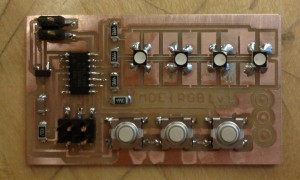
I started soldering before I remembered to take a picture:
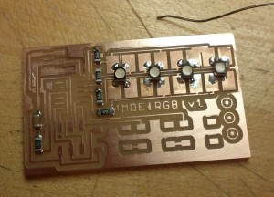
Soldering the components was much easier than the first time two weeks ago. The LEDs were the hardest part… something about their pins made them hard to stick to a solder ball. The huge pads might’ve contributed to that too. Finished board:
Programming
I needed a few extra packages to compile the example files (avr-specific headers, etc.). On Ubuntu you can run:
sudo apt-get install gcc-avr avrprog avr-libc binutils-avr
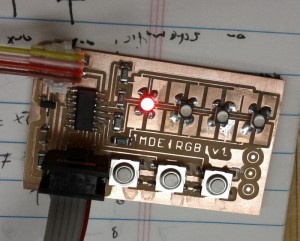
I worked off of Neil’s example programs, seeing how to set pin values and read input pins. I tried to get the first LED to light up red, and (surprisingly?) it worked:
I adapted one of the makefiles from the class page and pointed it to my C source file.
In lab I programmed it with the AVR ISP:
sudo make -f matt_rgb.make program-avrisp2
And I also used my FabISP:
sudo make -f matt_rgb.make program-usbtiny
Since I wasn’t using a crystal, I didn’t have to set any fuses.
I did bit-banging PWM to send bursts of voltage to each color cathode of the LEDs. I had good results running each LED for 100 microseconds, leaving each color on for some fraction of that time. I scan through the 4 LEDs with this pattern.
I made the board randomly go through RGB mixing values, rotating through the LEDs. When a button is pressed, it switches into a color experimentation mode where each button controls the amount of red, green, or blue.
In this mode, pressing the left two buttons together cycles the LED, and pressing the right two together resets the LED to weak white. Pressing the outer two buttons turns on all LEDs in this mode. Waiting about 5 seconds returns to the random color mode.

