The third time’s the charm! I had a few struggles but ended up with a working product. I used some extra components with my multiple attempts, but on the plus side I didn’t break any bits on the Modela.
Round 1: FabISPKey
I started out with the FabISPKey, milling with the images on Andy’s webpage. The printed directions in the lab are fine, and the fab modules defaults worked well for me without modifications (remember to change the mode when going from cutting the traces to cutting the board). My specific tips are:
- Make sure the board is securely fastened to the sacrificial board (with double-sided tape).
- Make the RML file after you have picked the correct origin. It will cut in the wrong place otherwise.
- When setting z position by lowering the bit onto the board, hold it while tightening the set screws. Otherwise it might lift up a bit and not cut at the correct depth.
- There are two set screws!
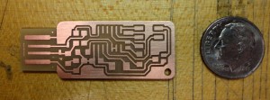
Here’s the board after milling. I forget to set the contours flag to -1 (see Andy’s page), so I had some extra copper bits to remove. The most noticeable one is on the tip of the USB connector.
I deburred the board by rubbing it with the steel wool in the lab. I stuffed it, expanding on my very basic previous soldering experience. I used flux and set the iron to 700. I started with the resistors and capacitors and did the 6-pin header, IC, and USB header last (in that order). I had some trouble keeping components in place until I tried the technique of dropping a solder ball on one pad, reheating the ball while placing the component on it with tweezers, then redoing both joints. That method worked well, even for the IC. The most difficult part was the tiny pins of the USB header. Following a suggestion I saw elsewhere, I hit all the pins with a big blob then removed the excess with the solder wick. The pins stay connected and clean then.
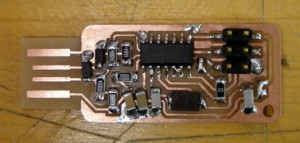
Here’s the stuffed FabISPKey:
I tried to program it, but the AVRISP programmer in lab wouldn’t recognize the board. After reflowing some joints and checking connections with the multimeter, I still couldn’t fix the problem. I shimmed the connector with some vinyl, to no avail. I gave up and made the FabISPKey.
Update: when I tried to program the board the next day, it worked! That is, the programmer recognized the board and flashed it successfully. The board was recognized by the computer. But when trying to program (no output device, just a test run) I received various angry protocol error messages from avrdude. So I assume that my original problem was a weak USB connection but additionally I have a hardware error.
Round 2: FabISP (with mistakes)
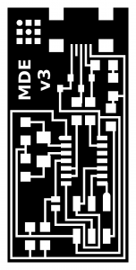
With no luck debugging, I milled a FabISP board to start again. I used the images on the class webpage. I wrote my initials in white in the big uncut area, but you can see that I wrote it too small to turn out well:
I stuffed the board again, going more quickly and easily this time. The finished board programmed successfully on the first try, but it wasn’t recognized by the computer afterwards. I thought the problem was around the USB connector, but not the power traces since the board received power during programming. Looking at the schematic, you can see that the data pins (marked + and -) implicate the diodes. Looking closer, I realized I put the diodes in the wrong orientation. My excuse is that in Andy’s design (which I did first), the diodes are in the same location but in opposite orientation. I flipped the diodes, but after this the programmer didn’t recognize the board. I hypothesize that I damaged another component with the heat of removing the components (heat gun sloppiness?), reflowing joints, or un- or re-soldering the jumper joints (I did this a few times in debugging). Sadly, I couldn’t revive the board.
Round 3: FabISP (success!)
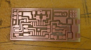
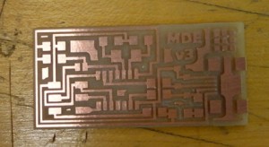
Learning from my mistakes, I milled another FabISP board. I made my initials bigger (and incremented my counter to v3):
It turned out well:
I followed the same procedures as before, and put the diodes in the correct orientation this time. I also used a crystal from a different part drawer (marked 20.000 :18 instead of 20.000 :16), but I haven’t done a test to see if that’s the key difference.
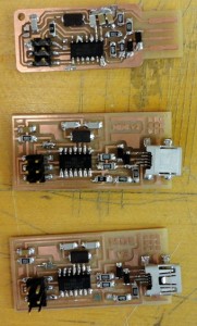
You can see my whole menagerie (and compare soldering results):
The third try programmed successfully and, when I desoldered the jumpers, did a successful mock flash.
Successful initial programming (using the firmware and instructions from the class page, reproduced here):
modela@ubuntu:~/matt_temp/firmware$ make clean
(output not shown)
modela@ubuntu:~/matt_temp/firmware$ make hex
(output not shown)
modela@ubuntu:~/matt_temp/firmware$ sudo make fuse
avrdude -c avrisp2 -P usb -p attiny44 -U hfuse:w:0xDF:m -U lfuse:w:0xFF:m

avrdude: AVR device initialized and ready to accept instructions
Reading | ################################################## | 100% 0.01s
avrdude: Device signature = 0x1e9207
avrdude: reading input file "0xDF"
avrdude: writing hfuse (1 bytes):
Writing | ################################################## | 100% 0.00s
avrdude: 1 bytes of hfuse written
avrdude: verifying hfuse memory against 0xDF:
avrdude: load data hfuse data from input file 0xDF:
avrdude: input file 0xDF contains 1 bytes
avrdude: reading on-chip hfuse data:
Reading | ################################################## | 100% 0.00s
avrdude: verifying ...
avrdude: 1 bytes of hfuse verified
avrdude: reading input file "0xFF"
avrdude: writing lfuse (1 bytes):
Writing | ################################################## | 100% 0.00s
avrdude: 1 bytes of lfuse written
avrdude: verifying lfuse memory against 0xFF:
avrdude: load data lfuse data from input file 0xFF:
avrdude: input file 0xFF contains 1 bytes
avrdude: reading on-chip lfuse data:
Reading | ################################################## | 100% 0.00s
avrdude: verifying ...
avrdude: 1 bytes of lfuse verified
avrdude: safemode: Fuses OK
avrdude done. Thank you.

modela@ubuntu:~/matt_temp/firmware$ sudo make program

avrdude -c avrisp2 -P usb -p attiny44 -U flash:w:main.hex:i
avrdude: AVR device initialized and ready to accept instructions
Reading | ################################################## | 100% 0.01s
avrdude: Device signature = 0x1e9207
avrdude: NOTE: FLASH memory has been specified, an erase cycle will be performed
 To disable this feature, specify the -D option.
avrdude: erasing chip
avrdude: reading input file "main.hex"
avrdude: writing flash (2020 bytes):
Writing | ################################################## | 100% 1.74s
avrdude: 2020 bytes of flash written
avrdude: verifying flash memory against main.hex:
avrdude: load data flash data from input file main.hex:
avrdude: input file main.hex contains 2020 bytes
avrdude: reading on-chip flash data:
Reading | ################################################## | 100% 1.60s
avrdude: verifying ...
avrdude: 2020 bytes of flash verified
avrdude: safemode: Fuses OK
avrdude done. Thank you.
avrdude -c avrisp2 -P usb -p attiny44 -U hfuse:w:0xDF:m -U lfuse:w:0xFF:m
avrdude: AVR device initialized and ready to accept instructions
Reading | ################################################## | 100% 0.01s
avrdude: Device signature = 0x1e9207
avrdude: reading input file "0xDF"
avrdude: writing hfuse (1 bytes):
Writing | ################################################## | 100% 0.00s
avrdude: 1 bytes of hfuse written
avrdude: verifying hfuse memory against 0xDF:
avrdude: load data hfuse data from input file 0xDF:
avrdude: input file 0xDF contains 1 bytes
avrdude: reading on-chip hfuse data:
Reading | ################################################## | 100% 0.00s
avrdude: verifying ...
avrdude: 1 bytes of hfuse verified
avrdude: reading input file "0xFF"
avrdude: writing lfuse (1 bytes):
Writing | ################################################## | 100% 0.00s
avrdude: 1 bytes of lfuse written
avrdude: verifying lfuse memory against 0xFF:
avrdude: load data lfuse data from input file 0xFF:
avrdude: input file 0xFF contains 1 bytes
avrdude: reading on-chip lfuse data:
Reading | ################################################## | 100% 0.00s
avrdude: verifying ...
avrdude: 1 bytes of lfuse verified
avrdude: safemode: Fuses OK
avrdude done. Thank you.
The board also shows up in the kernel log (see dmesg | tail) and with lsusb (as a USBtiny device).
Successful (mock) flashing of another board (I didn’t have another mini-USB cable to test a real target):
modela@ubuntu:~/matt_temp/firmware$ sudo avrdude -c usbtiny -p t44

avrdude: initialization failed, rc=-1

Double check connections and try again, or use -F to override this check.

avrdude done. Thank you.
Per Matt Keeter’s page, this result means that the programmer is communicating successfully but doesn’t find a target (which makes sense, since it’s not connected to anything to program). When I tried this with my broken FabISPKey, I got additional error messages at this step.
I also made a 6-pin cable. The connectors are in the inventory and press onto 6-wire cable (I peeled away the extra wires from a 9-wire cable) with a vise.
See it connected to the working FabISP:
Thoughts:
My soldering skills really increased this week (they started low though). I got better at debugging hardware circuits (in terms of testing various areas and components), but had no successful resuscitations. I wonder if the crystal is the problem, or if it’s just bad luck / low initial skill.
Thanks:
Jeremy for milling help and soldering pointers. TA David for debugging suggestions.

