For my very first laser cutting experience, I cut some sizing and folding test pieces (for my laser cutting notes, see the bottom of the page). I made the designs with cad_ui, exported them to SVG, used Inkscape to convert the SVG files to DXF, and finally loaded that into AutoCAD to use the Epilog printer driver. I want to do this in a less painful way in the future – getting sizes right in AutoCAD is a pain, and it’s harder to iterate on-site (even with a parametric design) because the loop is so long and unautomated.
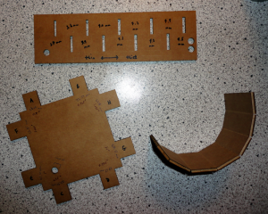
I knew I wanted to build tabs and slots (not sure on the right nomenclature), so I experimented with several size combinations. I made a slot tester for 0.9″ to 1.1″ in 0.025″ increments, which I tested on 1″ wide slots. I tested slot thicknesses from 3.7 to 4.5mm, in 0.1 increments.
I also wanted to try folding the cardboard with perforations from the laser cutter. I thought about drawing dashed lines, but got a good enough result just from varying the laser power settings for a straight line.
I tested speeds of 40 and 55 each with powers of 15, 20, and 25 (on the Epilog 120 watt laser cutter). A speed of 40 and strength of 25 almost cut through the cardboard, but right below that was good and left a clean bending joint.
Slot testers in action, next to the folding test strip:
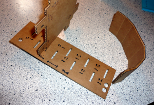 I decided on 3.9mm slots with 1″ widths exactly.
For my press-fit kit, I wanted to make something with a three-dimensional building block. I decided on making tetrahedrons that are assembled by folding and joined by shared tab connectors.
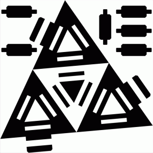
Here is the plan for one, from cad_ui:
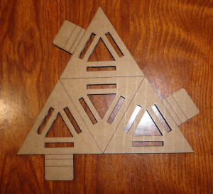
The three slots in each face can be used for connecting the tab of an adjacent face or with the external tab to link to another tetrahedron. The waist on the external tab is to account for the extra space from the linking tabs connecting three faces of every tetrahedron.
After a trial cut of one tetrahedron, I realized my design was too conservative for the tab depth (I was too worried about them hitting each other inside each unit). I increased those lengths and then cut a full sheet of tetrahedrons. The full cut (24 tetrahedrons) took about half an hour. I used a speed of 50, power of 20 for the fold lines and a speed of 35 with a power of 40 for the cut lines.
The final version of the core unit (notice the scoring lines for folding):
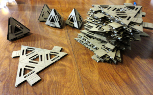
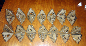
The army beginning to take shape:
After assembling all the tetrahedrons:
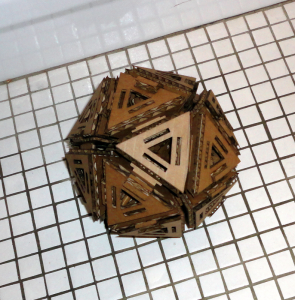
The core units can be joined together in many ways to make fun shapes. When using a connector in two or three of the slots on each face, the resulting structures are quite sturdy.
I made a helical truss:
And a complete sphere:
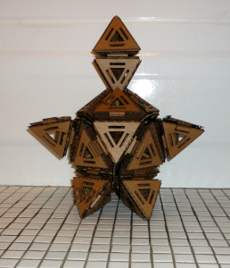
And a geometric man:
Laser cutting notes:
The instruction notebook in the fab lab has all the right steps, and is a good place to start. Here are my specific notes:
- Import your files into AutoCAD as DXF files (Inkscape can export this)
- Set the units to inches (type UNITS). Scale your drawing correctly (I could never get them right the first time). Use an existing feature where you know its true measurement.
- Draw a bounding box, get the dimensions correct (36″ x 36″). This is bigger than the material, but it’s what the instructions say to do. Draw a 36″ x 24″ bounding box if you want to mark your material constraints.
- Set all lines to 0.00″ width
- In AutoCAD, set the bounding box[es] to the “defpoint” layer, which should already be set to NO PLOT (see the Layer Manager)
- To cut, type PLOT. In the main settings, select “Window” for what to plot (not display), then select your 36″ x 36″ bounding box. The scale should be almost 1:1 (in inches). Pick portrait mode. You don’t need offsets if you selected the entire 36″ x 36″ box. In the advanced configuration settings, set 36″ x 36″ paper size and set up any color mapping you want to do.
- Check out the print preview, it should make sense. The top left corner in the preview is the top left corner on the cutter (when facing it). Then send to the cutter. You can do a preview run on the machine by running your job with the lid open. Do this and make sure it looks okay.
Thoughts:
- The biggest pain was going from my design files to plot-ready files on the lab computer, particularly with getting the sizes/scales correct. This may also reflect my lack of CAD skills. I think going to the fab modules directly is the right answer, but for this week I worried that they didn’t support color mapping.
- For cardboard, the direction of the corrugation is something to keep in mind. For some of my test cuts, the small pieces had corrugations parallel to the folding lines, which didn’t work well. For the full cut, I got lucky and they were almost always close to perpendicular.
- I wanted to experiment with a similar design in paper using the vinyl cutter, but I didn’t have enough time this week. I’m curious to explore perforation and folding there.
- I was quite happy with the speed and precision of the laser cutter, and I look forward to using it with more materials as the semester goes on.
Thanks:
Laia and Nicole for CAD help. A random guy in the lab for help on my first cut. Tim for helpful design discussions. Amanda for assembly help.

