This week I wanted to explore capacitive touch input. There are a lot of examples from the class, including Matt Keeter’s multi-touch input and Matt Blackshaw’s touchpad.
My goal was to make a number pad or small keyboard that could connect over USB directly to a computer (or phone?). On the touch input side, I wanted to use the Atmel QTouch library. It’s appealing as an existing solution and for the (supposedly) advanced detection and noise-avoidance measures it offers out of the box.
I spent a fair bit of time wading through the V-USB AVR driver code and assorted online examples to get a basic keyboard interface.
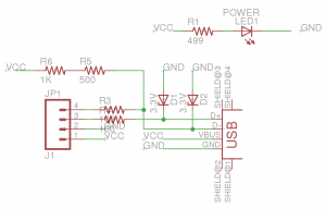
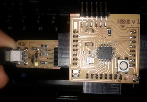
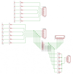
I designed, milled, and stuffed a small USB interface board for my Fabduino. I had to add a 20 Mhz resonator to the Fabduino to get it to run fast enough for USB. The USB board is basically the USB end of a FabISP, with Zener diodes to level shift the data lines and appropriate resistors. I added an LED on the input VCC. Here’s the schematic:
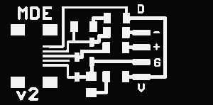
Here are the trace and board files:
I had to trick Fab Modules a bit to cut the board out since the edge is so close to the image border.
The board connects to two digital IO lines on the Fabduino, next to GND and VCC to power the Fabduino off USB power.
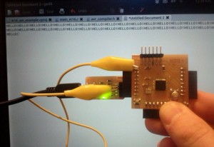
After many false starts, I got the USB keyboard working. Proper software initialization was the first key, and the second key was my oversight of the right hardware setup. The data+ pin has to be connected to an interrupt pin on the microcontroller (by default INT0, but the only other choice is INT1). To do this, I jumped the D+ pin to INTO (D2 on the Fabduino). With that, the board says “HELLO!” repeatedly.
For the keypad, I studied the advice in the Atmel QMatrix design guide and QTouch user guide. The main idea is digital pins as drive electrodes and analog pins as receive electrodes. The drive electrodes connect to rows and the receive electrodes connect to columns. The buttons interleave the two so that finger contact capacitively couples them.
I put 6-pin headers on the board to use the Fabduino as the brains. I put a ground trace between areas where the row and column traces run in parallel.
Schematic:
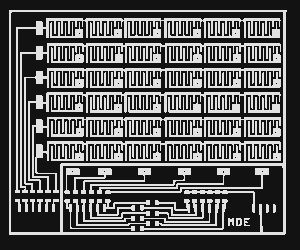
The board is pretty big to fit 6×6 keys (~3″x4″), so it took awhile to mill on the Modela. Here are the trace, hole, and board files:
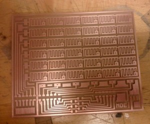
Milled board:
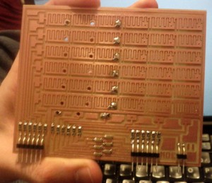
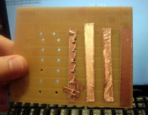
I stuffed the passive components on the keypad board. I ran into trouble with the vias: I made the holes small, planning to use copper wire straight through. However, the copper wire in the lab is actually magnet wire! It’s terrible stuff if you don’t know what it is, since it’s insulated but looks like raw copper to the naked eye. I had to use other, thicker wire but the original holes were too small. I expanded them on the drill press, but the smallest bit was too big and it looks pretty bad:
Since we didn’t have big double-sided PCBs, I made the vertical traces on the back with vinyl-cutter-style copper.
I only did one column with the bad wire we had available. I plan to do the rest with better copper wire that can fit in the original holes.
Sadly, configuring the QTouch library and integrating it with the USB code has been tough going, so no working examples yet!

