Final Project
For my final project I settled on the idea of making a nicely packaged Iron Man arc reactor that responded to the wearer's pulse. This idea started all the way back in Week 10 and kept growing from there. I started out by trying (and failing) to build my own photoplethysmograph (detects volume of blood in tissue of extremities using light reflectance). I went through many different iterations based on previous schematics, modified for the part values we had at hand. The math worked out on my circuits, but the circuits themselves didn't work. I decided to instead buy a photoplethysmograph (in my case, the open source Pulse Sensor Amped). Lesson #1: Two day shipping takes much longer than two days if you order on a Thursday afternoon. Especially around the holidays. While building circuits and then waiting for the sensor to arrive, I worked on other aspects of this project.
I initially made a charlieplexed board to back-light my Iron Man arc reactor (week 11).
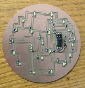
Shortly after stuffing the board I realized that charlieplexing is pointless for this particular application. I want all of the LEDs to be on at the same time or all of them pulsing simultaneously; either way, this is easily accomplished by instead wiring the LEDs in parallel and connecting them to a single output pin. In addition to making the circuit easier to control, the LEDs appear much brighter because they are no longer pulsing one at a time. Click here for my design. Unfortunately, in this updated design, I made the cutout path the incorrect radius. I fixed it on the scroll saw, but I haven't added the circuit cut-out file because it is currently incorrect.
I stuffed the board; it lights up!
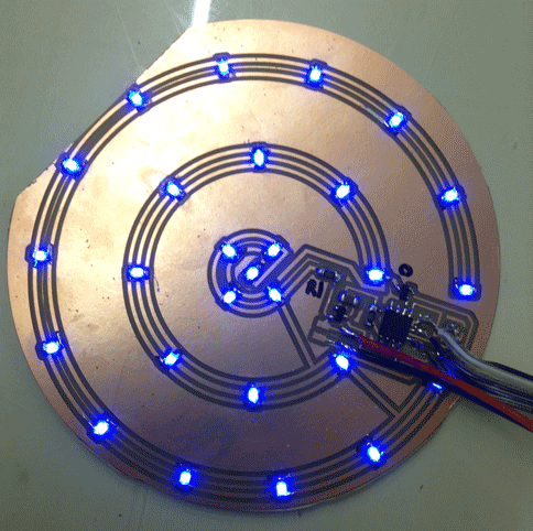
I put this LED panel behind a faceplate with the silhouette from the Iron Man 2 arc reactor with a light-diffusing layer in between. I wanted to make the light-diffusing layer out of materials readily available in the class inventory. After a bit of research, as described in week 14, I decided to try epoxy with talcum powder in suspension. The board was the first iteration of my parallel LED circular backplate design, and worked fairly well. I programmed it to pulse as if in response to a heartbeat, but without any actual sensor input. This combination gave a nice effect.
The case surrounding the pieces is shown in the center of the following picture.
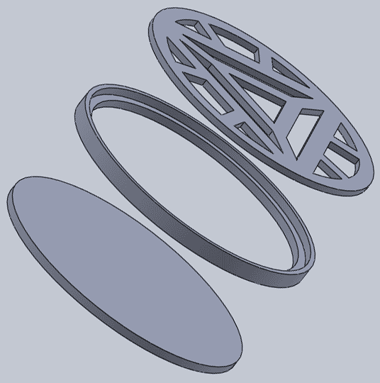
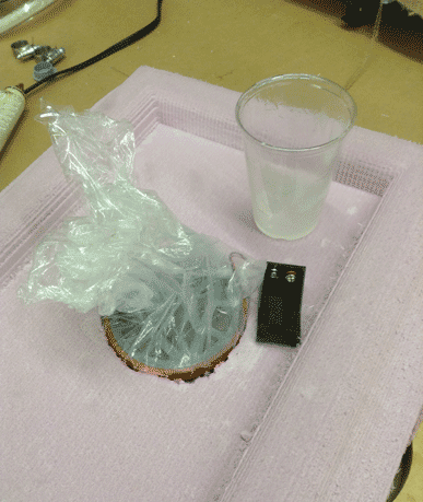
I was planning to press fit the top and bottom and use the epoxy fill to make all of the joins extra secure. However, my work on the scroll saw left unexpected gaps at the bottom, which weren't watertight. I covered the back with a piece of vinyl, but it didn't really help; epoxy leaked around the edges, making a mess. I quickly cut out a circle in some scrap foam, plugged it with a failed MDF cutout (the edges got really squirrelly and sad-- MDF doesn't work very well for thin walls), sealed it with plastic wrap, and put the reactor inside. Epoxy still managed to coat the outside, but the hacked mold prevented further leakage. I sanded this down after the epoxy cured.
So there were plenty of mistakes to fix on the next iteration:
-cutout path (the electronics all fit on the board, but the cut-out path was too big for the circuit blank)
-Add a 2x3 header- the shop was out of most header sizes, so I soldered six strands of wire to the pads instead. I used single pins from strips of connectors as the method for plugging into the ISP (necessary since we only have multi-stranded wire). I was getting inconsistent results and the pins were too crowded to fit correctly into the ISP, so I couldn't program this week.
-Add resistors to each leg of the parallel circuit (for a great explanation click here). Thanks Jean-Francois!
Tips and tricks:
-Adobe Illustrator (and probably any other vector graphics program) makes much cleaner circular circuits than Eagle.
-mark cathodes of LED pads with a marker. This way I didn't need to keep referencing the schematic to get proper LED orientation as I went; this is especially important for more complex wiring schemes.
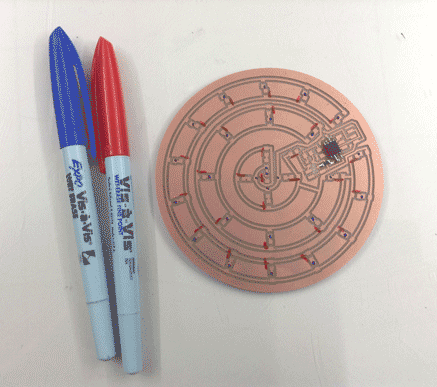
I started the next iteration of the design by redesigning my schematic to include 27 more resistors (one for each leg of the parallel LED circuit) and an extra pin-out to connect the pulse sensor to. Unfortunately, I accidentally printed the circuit with the old version of pin outs (therefore no connection for the pulse sensor. This was easily corrected by jumping 0ohm resistors across wires to a pad for attachment. Updated traces and cutout path. After a bit of debugging (replacing my 5V regulator and mosfet), my board became programmable. I was able to get the circuit to fade like the prototype board, so I knew that that part of the circuit worked. I then moved on to the heartbeat sensing portion. This proved much more time consuming than expected (as I've come to expect. My professor for this class is fond of saying that making things takes a factor of pi times longer than you expect... and if you've already taken into account that factor of pi, it still takes a factor of pi longer). Finally, after much effort, I figured it out. Here's the maiden voyage of the circuit:
After bashing my head against the wall for a few hours trying to get the example code working on my ATTiny45, I figured out that I didn't actually want to detect heart rate, but rather the ebb and flow of blood, which would naturally produce the desired fading effect centered about each pulse. This was done using a simple analog read and map to possible output voltage. Commented code can be found here. This code takes the output directly from the pulse sensor and maps it to LED brightness, resetting every ~5 seconds to get rid of max and min outlier values.

 '
'
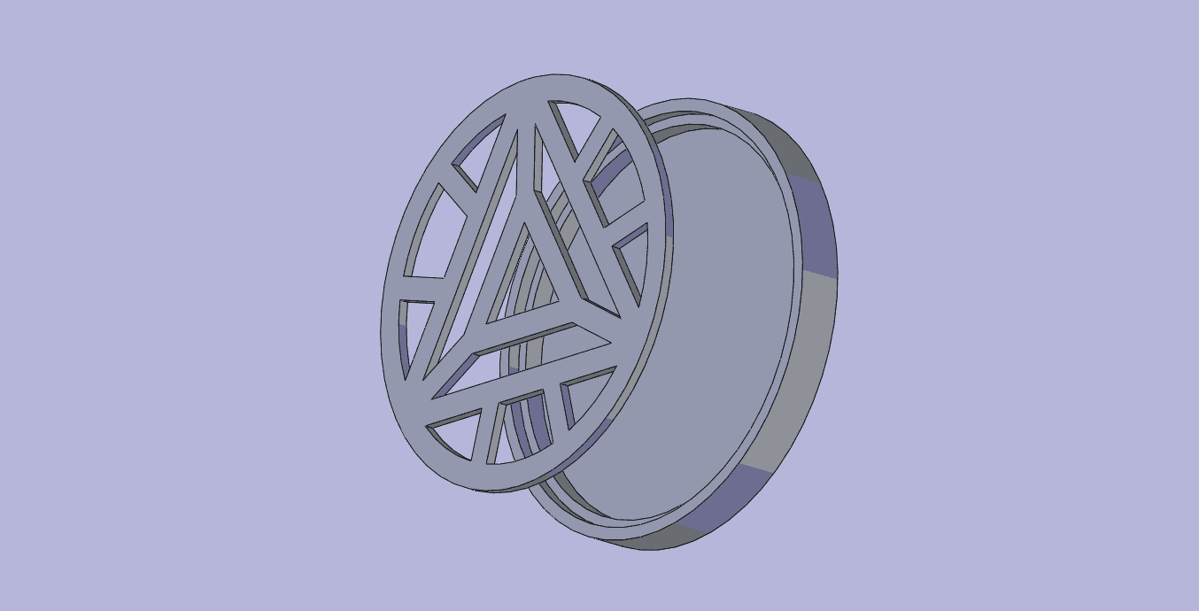
With Charles' help I 3D printed my cases for both circuits on the MakerBot, using red ABS and default settings. The case was updated to be watertight, holding the circuit board above a solid base. I water jetted the front plate, which took 5.5 minutes. Next the plastic pieces were laser cut and press fit into the front plate, sanding when necessary. I found there to be a kerf in the materials, which meant that the pieces fit better with a specific side up. I drilled 5 holes into the side of the case to allow wires to pass through; power and ground from the battery. down-regulated power and ground to the pulse sensor, and the pulse sensor output. I then soldered the pulse sensor leads to these [insulated] wires, leaving the sensor wires easily accessible. Once these steps occurred and the circuit was functioning as desired, I clipped the 2x3 header (too tall for the case when the front panel is added) and press fit the front plate into the case. It should sit nicely on the ledge, approximately flush with the height of the outer walls of the case.
Friends enjoying the toy:
Future improvements:
-Make the board re-programmable and the case less permanent, allowing for re-coding
-Make the board reset when it powers on
-Add the last piece of plastic to the front plate. I left it out to bring the switch up through it with the plan to notch the piece and replace it, but didn't have time to do so. The exacto wasn't quite beefy enough to cut through the plastic and the piece was too small to scroll saw without fear of losing my fingers. It seems best to laser cut a new piece and slot it over the switch
-Find SINGLE STRANDED wire to make my jump connections. The small strands are prone to breaking and shorting, both of which are undesirable.
-Sew a mounting pocket for the Arc Reactor. I was initially looking into a belted design, but I think that embedding a pocket in a shirt or undershirt would be much more comfortable.
-At some point, I would like to build my own pulse sensing board and get it working.
Summary
WHAT I DID: I manufactured a sturdy, well-packaged Iron Man Arc Reactor replica that responds to the wearer's heartbeat. This was a good balance of 2D design (laser cutter, modela, and water jet), 3D design (3D printing), electronics (input and output devices, circuit design for the output board), coding (the sketch running on the microcontroller), and hand-tooling (drilling, filing, soldering).
MATERIALS (final design only)
Name |
Parts I used (Part #) |
Amount Used |
Surface Mount LED |
160-1889-1-ND | 27 |
N Mosfet |
NDS355ANCT-ND | 1 |
5V Regulator |
LM3480IM3-5.0/NOPBCT-ND |
1 |
Resistors |
n/a |
n/a |
0Ω |
311-0.0ERCT-ND |
1 |
100Ω |
311-100FRCT-ND | 27 |
1kΩ |
311-1.00KFRCT-ND |
1 |
10kΩ |
311-10.0KFRCT-ND |
1 |
Capacitor (1uF) |
445-1423-1-ND |
1 |
ATTiny45 |
ATTINY45V-10SU-ND | 1 |
Heartbeat Sensor |
Pulse Sensor Amped |
1 |
Slide Switch |
401-2012-1-ND | 1 |
2x3 IDC Connector |
649-71600-006LF |
1 |
2x3 Header |
649-95278-101A06LF |
1 |
In System Programmer (ISP) |
FabISP (week 3) |
1 |
9V Battery |
|
1 |
Battery Holder |
BH9V-W-ND | 1 |
6”x4” Copper Circuit Blank |
|
1 |
ABS Filament |
|
2.7in |
Epoxy |
|
~1/8 cup |
Talcum Powder |
|
A few pinches |
1/8” Aluminum Sheet |
|
5”x5” |
1/8” Plastic Sheet (to diffuse light) |
|
5”x5” |
One of my goals in making this project was to use the supplies on hand rather than going out and buying new materials. Working with limited resources seemed like a good real-world challenge. Thus, most of the supplies (besides the Pulse Sensor Amped) were free to me. When budgeting for this project if doing everything out of pocket, I would plan to spend around $50 on supplies. $25.00 for the Pulse Sensor Amped, $17 for the water jet job, about $30 on 12"x12" sheet of 1/8" aluminum (smallest sheet available at McMastercarr), $4 for 12"x12" sheet of 1/8" HDPE, and approximately $10 on components and miscellaneous other items.
I would consider this project a success, with the caveat that there are improvements that should be made before I would consider it truly finished. I wanted a clean, good-looking board and overall project that, ideally, didn't use glue to hold itself together (I've become enamored with press-fitting since being introduced to it last semester). The Arc Reactor has a beautiful silhouette and pulses with heart-rate, as I set out to do.