Output Devices
This week's assignment: make a board with an output device and make it do something. I decided to stick with my plan from last week: make a pulsing Iron Man Arc Reactor. I started by working on an example board. This 20-LED charlieplexed board and corresponding code can be found here. I made the single-layer example rather than using the vinyl cutter to mask parts of the circuit. This added 20 0Ω resistors to the design (16 of which were necessary and 4 of which appeared only to be there for symmetry) but was much quicker and easier. And, when I transitioned to the second, non-gridded board, this design carried over very nicely.
Problems I ran into with the example LED array:
-Make sure all components are arranged in the correct direction if necessary. Our surface mount LEDs had their cathodes marked with a small protruding green line.
-Sometimes the issue IS the hardware. I tried programming the microcontrollor for a long time with the shop's avr mkII ISP, to no avail. Then, as soon as we swapped out for a different ISP, my board was able to program on the first try.
Example board:
Video Nov 20, 1 51 44 AM.mov from K Zimmerman on Vimeo.
After successfully completing the example board I wanted to convert the charlieplexed board into a large circular backplate for my Arc Reactor design. I laid out a schematic based on the example board; still 20 LEDs, but spread out in a fairly evenly spaced pattern on a circular disk. I took out the unnecessary 0Ω resistors in the bottom row of the example, and added others in to hop the looping traces when necessary. Below is my board layout:
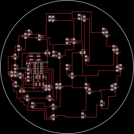
**note that the LEDs are all aligned so that vertical LEDs have the anode above the cathode and the horizontal LEDs have the anode to the left of the cathode. The LED denoted "U$9" is the only upside-down LED according to this logic.
Click here for the traces file used to mill the traces of this board.
Click here for the outline file used to cut out this board.
I programmed this board using the example code found here. (LED array →hello.array.44 row: 'C')
The Arc Reactor back-light:
Video Nov 19, 8 17 08 PM.mov from K Zimmerman on Vimeo.
Unfortunately, I managed to break my circuit when I removed the 2x2 header to make my circuit flatter. I instead ran long ground and power wires from the 9V battery to the pads where the header used to be. I ripped up a small section of leads under the header and accidentally popped extra components off with the heat gun. I fixed my components and ran a small jumper wire, but my circuit only rewarded me with a few sad flashes before reverting back to its unresponsive state. I even replaced the microcontroller for fear that I overheated it, but still was unable to revive my circuit. i will either do more troubleshooting in the coming week or build another circuit (the hard part is done, I just need to rerun my files and solder components).
Arc reactor Front Plate:
This plate is modeled off of the arc reactor design from Iron Man 2. I wanted to make this out of opaque black acrylic so that it was silhouetted when back-lit and sleek when viewed otherwise. However, we were out of black acrylic, so I settled on thin wood because it is light, easy to paint black, and opaque.
Click here for the dxf file I used to laser cut the front plate
For next week:
Translucent sections of the front panel: I would like to have the light emitting from the front plate be very diffuse; I don't want to be able to see individual LEDs. I played around with different surface finishes on clear acrylic but raster etching, distance, and sanding did not produce the desired effect. Charles, our awesome shop guy, suggested that I look into HDPE because it has the frosted effect all the way through rather than just on the surface. I plan to look into some combination of HDPE, sandblasting, layering contact or tracing paper, and translucent casting materials over the next week. Another option may be importing my front plate .dxf into Eagle (apparently possible) and lining up all of my LEDs such that they are directly under the opaque parts, such that none of my LEDs are directly behind the clear panels.
Mill, stuff, and program another board. Use the small 9V connector instead of the case and/or add a switch to the circuit. Code the charlieplexed array to pulse and fade slowly.