Embedded Programming
This week's assignment: program the circuit board made during Week 6.
Just a reminder:
 ← Board from Week 6
First things first: buttons arrived in my lab, so I was able to solder the push-button onto my board.
The majority of my limited electronics experience has been with Arduino. I decided to program my board in an environment I was comfortable with so that I could focus on the programming aspect more-so than the tracking down of other software that may or may not work for me. Hi-Low Tech from MIT's Media Lab has a great tutorial for converting the ATTiny44 (and ATTiny45 and ATTiny85) microprocessors to be compatible with the Arduino environment.
My initial try didn't work. I kept getting errors such as "not in sync." Around the same time my fabISP decided to stop working-- my computer just pops up the "USB Device has Malfunctioned" message whenever I connect it. After reworking all of the solder joints and triple-checking connections, the board worked for a few minutes before giving up on me again. So I gave up on it and decided to use the AVRISPmkII to debug my program rather than try to debug my programmer. I tried again but still was getting errors, so I built another board just in case the issue was in the hardware. Additionally, I updated my circuit design to have an external pull-up resistor on the button pin. The same thing can be done internally using the fuses in the ATTiny44A, but the external resistor was much more intuitive to me.
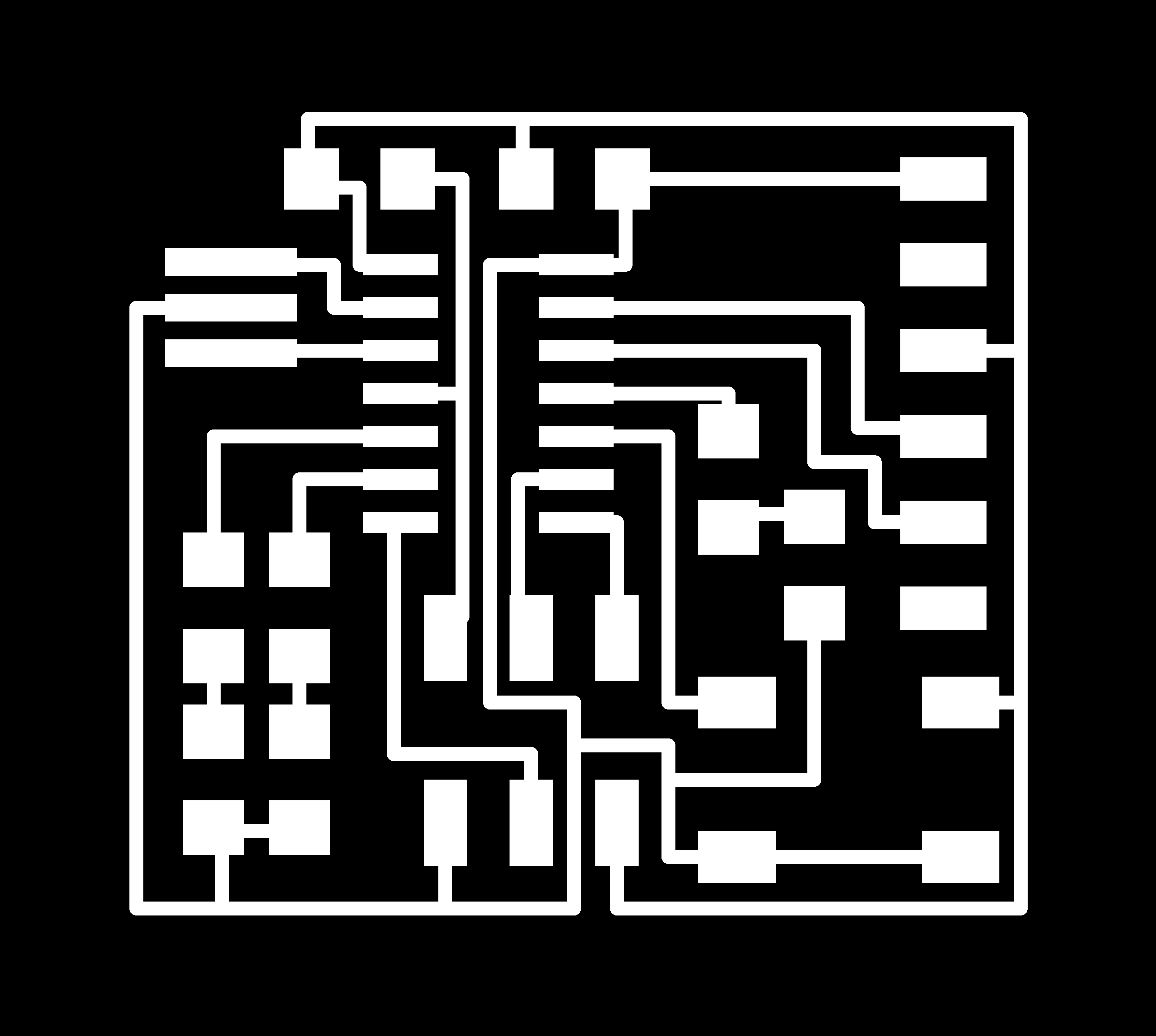
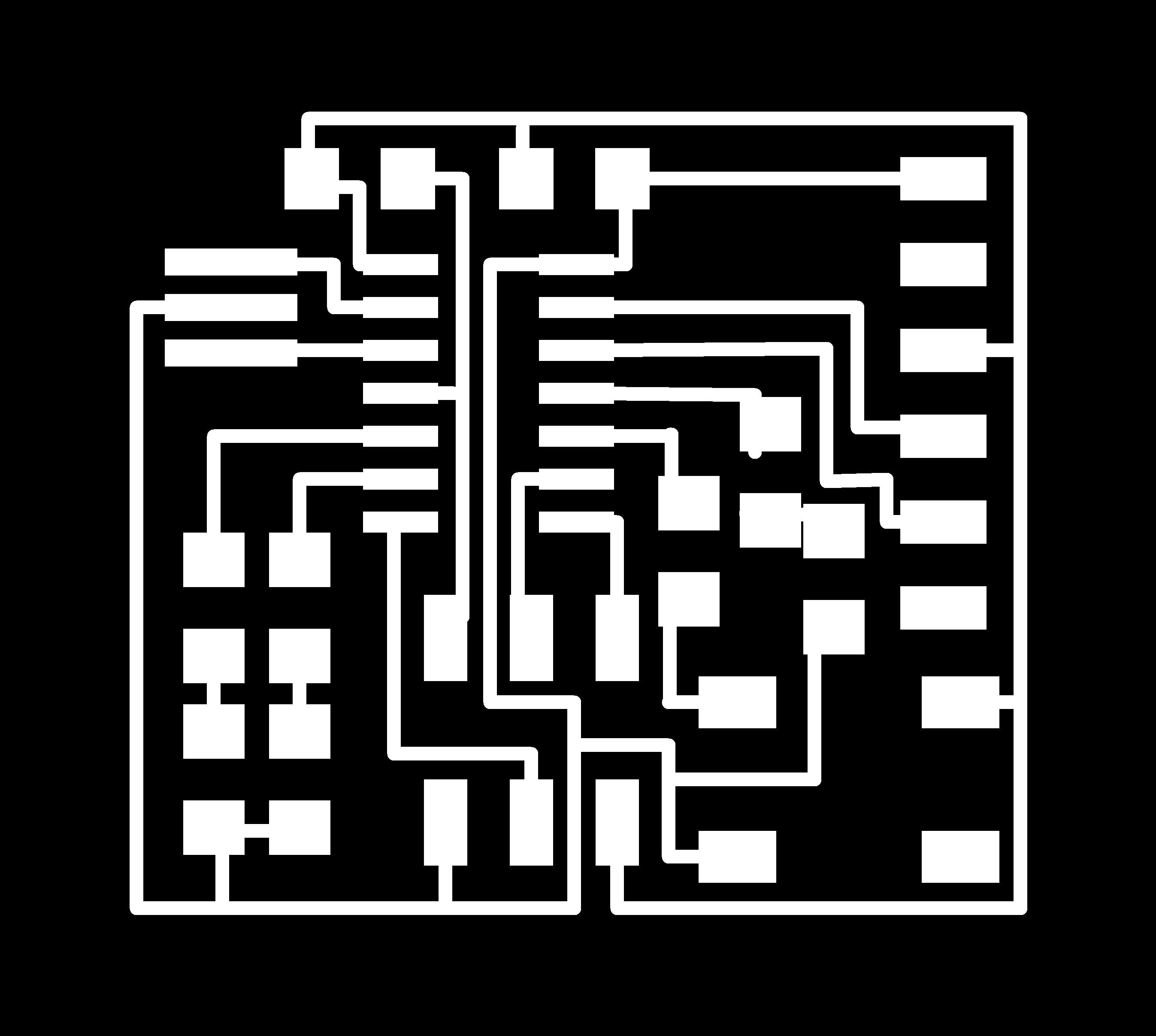 ← Updated Circuit Design
 ← Corresponding outline for cut-out path
I milled and stuffed the board as described in Week 6. I tried to load a quick Blink file onto the new board, but got the same error. At this point I had figured out that the most likely culprits were the programmer or the LED circuit board, and the board was looking less like it was the problem (unless there was a fundamental flaw in my design, which is unlikely given how many nearly identical boards I compared mine to while designing it). I asked Rob, one of the TAs for help, and we tried a different computer (a Mac this time instead of my windows). It worked the first time... and now I have two working boards.
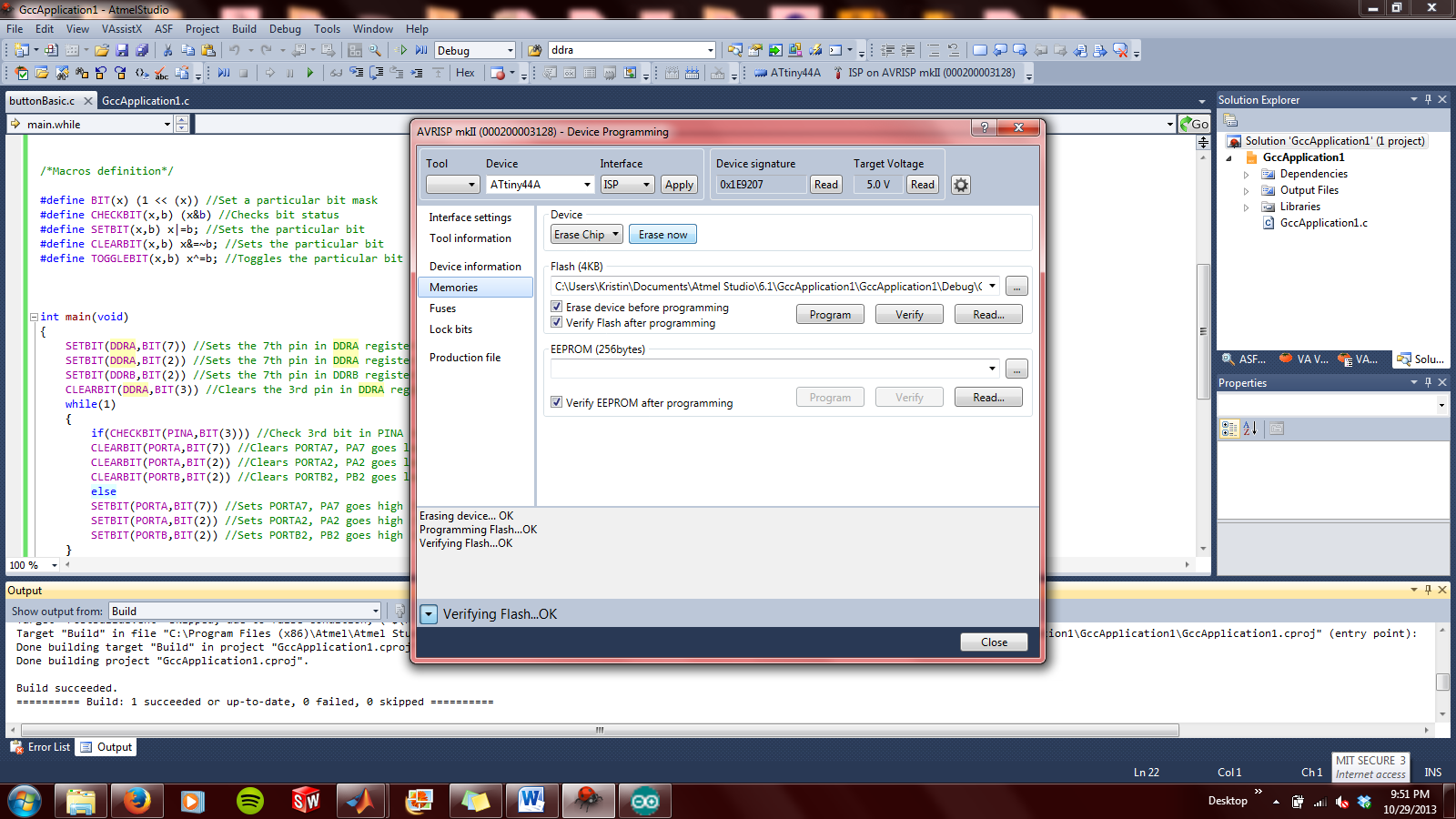
I spent some time searching for solutions to my Arduino connectivity problem (the mkII is recognized on my computer, just not in the Arduino IDE) and coming up empty, I decided to try Atmel Studio. This is a free software for programming microprocessors. The layout feels like a crossover between MATLAB and Eclipse, which made transitioning to this format a bit easier. One of the most useful things about this software is that everything is consolidated into one place... no need to find AVR Dude, or outside drivers, or any of the other little bits of software that inevitably need tracking down. This being said, the Arduino Libraries seem a lot more intuitive for beginners.
Steps for creating a program in Atmel Studio 6:
1. File → New Project → GCC C Executable File
2. Select your microcontroller: I used an ATTiny44A for this design
3. A basic code outline with information, a library import, and a main loop block for code will pop up. Get coding.
4.Build Solution (in the quick toolbar or Build → Build Solution or F7)
5. To program your device: Tools → Device Programming → Memories … then click “Program”
**Note: clearing your previous program will both turn the LEDs off and help you check that the file is indeed being overwritten.
This pin-out schematic was incredibly helpful when modifying code (especially non-Arduino code, in which the pin name rather than a single integer must be used):
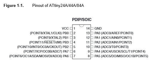
The ATTiny44A data sheet and ATTiny44A data summary are both good references.
 ← This is my first circuit board. I loaded a very basic code to turn the LED pins HIGH in order to make sure all of the LED traces were functional. Note the little jumper wire at the top of my circuit: I soldered a resistor vertical (to prevent shorts) and jumped it to VCC so that my button input pin wouldn't be floating (the same result can be achieved using the microcontroller's internal pull-up resistor).
 ← My second board with all LEDs lit. I decided to test multiple colors and styles of SMD LEDs on this one. My conclusion: blue LEDs are pretty, but the white LED was by far the brightest. I used 500Ω resistors on each LED-- I would play with lower resistances on the green and blue LED next time in order to increase brightness.
Code for my 3-LED circuit:
/* blinking_led.c
*
* This code blinks the LEDs on PORTA PIN 2, PORTA PIN7, PORTB PIN2 i.e PA2, PA7, and PB2 of the AVR board.
*
* The LEDs are wired so that they will be ON when the output is high and OFF when the output is low.
*
* The "special function registers" used in this program are:
* DDRA -- Port A Data Direction Register
* A high (1) value indicates output, low (0) is input.
* We set the 7th bit in DDRA to configure the PA7 pin as output pin, etc.
* PORTA -- Port A Data Register
* This is used to set the output value for each of the port A pins.
* PORTB -- Port B Data Register
* This is like PORTA, but for Port B
*/
#include <avr/io.h>
#include <avr/interrupt.h>
/*Macros definition*/
#define BIT(x) (1 << (x)) //Set a particular bit mask
#define CHECKBIT(x,b) x&b //Checks bit status
#define SETBIT(x,b) x|=b; //Sets the particular bit
#define CLEARBIT(x,b) x&=~b; //Sets the particular bit
#define TOGGLEBIT(x,b) x^=b; //Toggles the particular bit
void WaitMs(unsigned int ms);
int main(void)
{
SETBIT(DDRA,BIT(7)) //Sets Direction of 6th pin of port B as output
SETBIT(DDRB,BIT(2))
SETBIT(DDRA,BIT(2))
while(1)
{
//TODO:: Please write your application code
SETBIT(PORTA,BIT(7)) //Sets PORTA7 as high (turns on LED)
SETBIT(PORTB,BIT(2)) //Sets PORTB2 as high (turns on LED)
SETBIT(PORTA,BIT(2)) //Sets PORTA2 as high (turns on LED)
}
return 0;
}
← Single LED Blink Implementation
Single LED Blink Code:
//Modified from code by doxygen found on http://www.ladyada.net/learn/proj1/blinky.html
// this is the header file that tells the compiler what pins and ports, etc.
// are available on this chip.
#include <avr/io.h>
#include <avr/interrupt.h>
// define what pins the LEDs are connected to.
// in reality, PD6 is really just '6'
#define LED 7
// Some macros that make the code more readable
#define output_low(port,pin) port &= ~(1<<pin)
#define output_high(port,pin) port |= (1<<pin)
#define set_input(portdir,pin) portdir &= ~(1<<pin)
#define set_output(portdir,pin) portdir |= (1<<pin)
// this is just a program that 'kills time' in a calibrated method
void delay_ms(uint8_t ms) {
uint16_t delay_count = 1000;
volatile uint16_t i;
while (ms != 0) {
for (i=0; i != delay_count; i++)
ms--;
}
}
int main(void) {
// initialize the direction of PORTD #6 to be an output
set_output(DDRA, LED);
while (1) {
// turn on the LED for 200ms
output_high(PORTA, LED);
delay_ms(200);
// now turn off the LED for another 200ms
output_low(PORTA, LED);
delay_ms(200);
// now start over
}
}
← 3-LEDs and a Button Circuit
Finally, code for turning my LEDs on and off using a push button:
/* LEDSwitch.c
*
* This is modified from code by Prashant Patil
* found on http://fab.cba.mit.edu/classes/863.11/people/prashant.patil/ep.html
*
*/
#include<avr/io.h>
#include<avr/interrupt.h>
/*Macros definition*/
#define BIT(x) (1 << (x)) //Set a particular bit mask
#define CHECKBIT(x,b) (x&b) //Checks bit status
#define SETBIT(x,b) x|=b; //Sets the particular bit
#define CLEARBIT(x,b) x&=~b; //Sets the particular bit
#define TOGGLEBIT(x,b) x^=b; //Toggles the particular bit
int main(void)
{
SETBIT(DDRA,BIT(7)) //Sets the 7th pin in DDRA register to make PA7 an output pin
SETBIT(DDRA,BIT(2)) //Sets the 7th pin in DDRA register to make PA2 an output pin
SETBIT(DDRB,BIT(2)) //Sets the 7th pin in DDRB register to make PB2 an output pin
CLEARBIT(DDRA,BIT(3)) //Clears the 3rd pin in DDRA register to make PA3 an input pin
while(1)
{
if(CHECKBIT(PINA,BIT(3))) //Check 3rd bit in PINA register
CLEARBIT(PORTA,BIT(7)) //Clears PORTA7, PA7 goes low (turn led off)
SETBIT(PORTA,BIT(2)) //Sets PORTA2, PA2 goes high (turn led ON)
SETBIT(PORTB,BIT(2)) //Sets PORTB2, PB2 goes high (turn led ON)
else
SETBIT(PORTA,BIT(7)) //Sets PORTA7, PA7 goes high (turn led ON)
CLEARBIT(PORTA,BIT(2)) //Clears PORTA2, PA2 goes low (turn led off)
CLEARBIT(PORTB,BIT(2)) //Clears PORTB2, PB2 goes low (turn led off)
}
return 0;
}
I thought this code worked when I programmed my circuit, but I don't think the code updated (even though I cleared the microcontroller's memory and closed all other files in Atmel Studio). The LEDs are blinking in a different pattern than the one with which I coded them (I even switched to having part of the pins high and part of the pins low to make sure that I wasn't thinking about high and low backwards).