Input Devices
For our input devices week I wanted to detect heartbeats such that I could make an array of LEDs blink in time with the wearer's heart. Picture an Iron Man arc reactor like the one below from Think Geek, but controlled by heartrate.

I looked into many methods for detecting heartrate, from sticking electrodes to your chest to using a microphone as an input. The former idea didn't seem appealing and the latter seemed to susceptible to noise, so I settled instead on Infrared Plethysmography. Plethysmographs measure changes in volume of an organ/body. In my case it aims to measure changes in volume of blood in an extremity--either a finger or an earlobe-- by attaching an infrared (IR) LED and an IR sensor to either side of the wearer's finger, pointed towards each other. Differing amounts of light are absorbed depending on volume of blood in the extremity. By triggering either on the rise/fall of the ensuing sinusoid or at a suitable min/max plateau value, voltage input into the microcontroller should pulse in time with the wearer's heart.
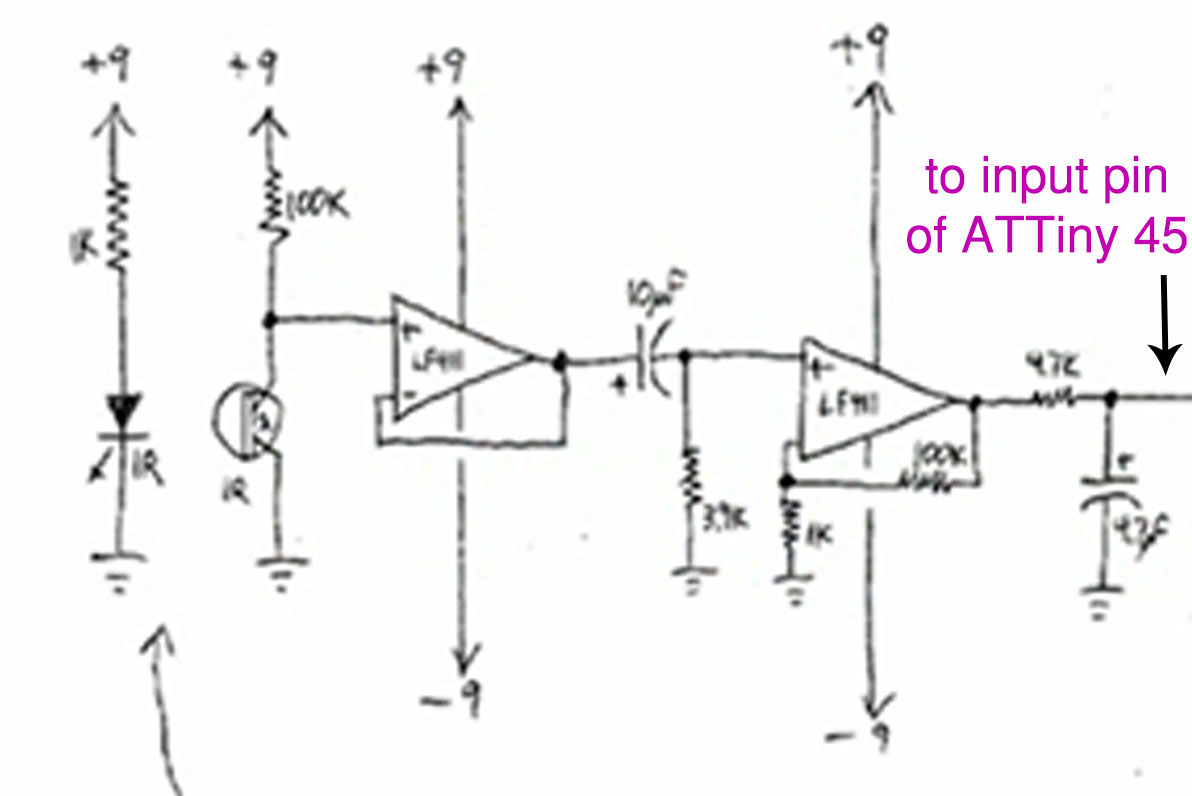
I started by looking at existing circuits. Below are the two main circuits I considered, although the one listed on top appeared to have a much cleaner signal coupled with a simpler circuit (and was therefore the one that I mostly worked from).
-DIY Plethysmograph Circuit with Mini Oscilloscope
-Heartrate Display LED t-shirt
I made the first circuit input into an i/o pin of an ATTiny45 rather than the oscilloscope used in the tutorial. I used the same base capacitor and resistor as in previous weeks (for timing?). I then drew everything up in Eagle. This was the first time I started modeling in schematic view rather than board view. This was slower at first, but allowed for the use of many helpful features- such as auto-routing (which didn't quite work for me, but was fun to play with). Below is the circuit:
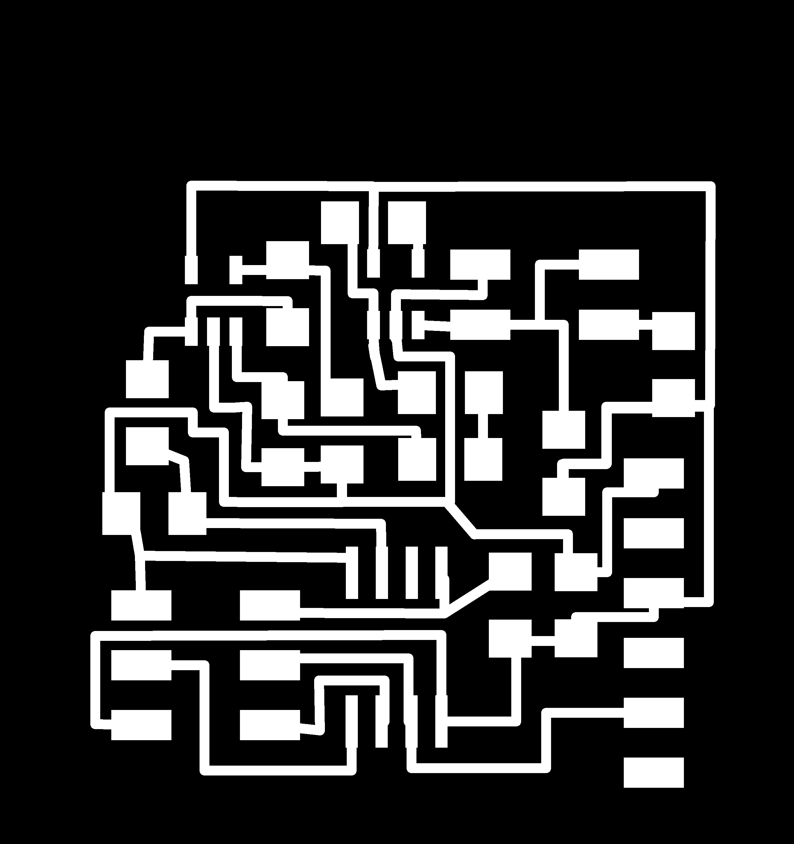 Traces
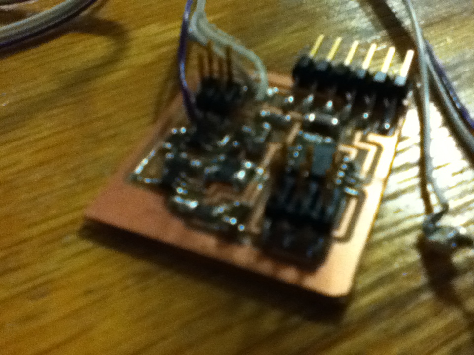 Closeup of board

This final picture shows a zoomed out view of my board. The long wires are to allow the circuit to remain stationary while adjusting the IR LED and phototransistor. I hooked the final circuit to an oscilloscope such that I could monitor input to the microcontroller from the IR Plethysmography circuit.
This circuit, unfortunately, ran into a few issues
1) Lack of components. Some of the resistors and capacitors used in this tutorial are not part of the standard fab lab inventory. I ended up going by the "next closest thing" rule and made sure to keep proportions the same where it mattered in the op-ams
2) The circuit measures light levels, as wanted, but does not detect anything heartbeat related. Video below:
heartbeat3 from K Zimmerman on Vimeo.
Random Tidbits:
-In Eagle: File --> Export -->Partlist
-Eagle Tutorial: designing custom library components
-Eagle Tutorial: converting from Schematic to PCB
To look at for next week (provided that I can get this prototype working):
- I would like to add a voltage regulator to the board (so that I can hook my circuit to 9V external power source without frying anything):
-Tutorial on how to make an LED arc reactor using an old heartrate monitor.
-Quadruple check orientation of IR LED and phototransistor. The data sheets had the indent in the package corresponding to a different pin for each (the indent corresponded to pin 1 in one schematic but pin 2 in another).