Circuits and Final Project Updates
This week we were tasked with making our own HelloISP board. The rules: we had to recreating the HelloISP board ourselves in Eagle before milling it.
Here's my board schematic from Eagle. The labels are really helpful when gathering all of your components to stuff the board. The component libraries I was working from had diverged at some point, so I needed to include parts from multiple libraries (not the end of the world, just a useful note if you are working from fab.lbr). I ran into a few issues in Eagle. The first was not being able to space my wires correctly in tight spaces: this was remedied by reducing my grid size to .01 (and later, the smallest possible increment because my wire spacing was too tight to mill). Second: some of the components only show up in schematic view rather than board view; I found it lay all of my parts out in schematic view first and then go to board view (moving the components to the correct space on the screen, because they are offset off of the bottom left of the board) to wire it. Third: wires and components are on different layers. Once I started adding wires I was no longer able to modify the position of my components without deleting all of the wires. I haven't yet figured out how to move components on the red layer with wires still down. Fourth: draw the cutout around your board before exporting the guts; this will make the two file origins [mostly] line up for milling.
Turn off all layers except the ones with your component pads and wires (Red and Blue for me). Export the file as an image (File-->Export-->Image). Make sure to set the quality at at least 2000dpi and check "monochromatic." The file should save as a .png with traces in white and background in black.

This is the outline for the circuit. Make sure to draw this before exporting your traces, but be sure to turn off the layer before exporting the traces and then turn off the traces to export this outline file. Again, use at least 2000dpi and check "monochromatic."
This is a screenshot of my settings for the tooling of the traces on a Roland Modela. The default settings in the fab module under "mill traces 1/64" worked well. Likewise, the defaults for "mill outline 1/32" worked (after changing z-depth to 1mm deeper).
I cut three boards before getting one that milled correctly. They are pictured above in order of cuts from left to right. The outline of the first board, although it appeared correct in the exported Eagle file, printed slightly too high, cutting of my ground trace at the bottom of the board. I then made the outline slightly bigger than looked necessary because it seemed to shift upwards each time and milled a second board. The second board had some traces that weren't completely milled out, creating many short-circuits in the region under the ATTiny. The third one took some playing around with, but after I generated a few new spacings in Eagle and looked closely at the generated toolpaths in the Fab Module for my problem areas, everything milled correctly.
Here is my final board. Notice that there is space between each of the traces. It took a lot of playing around with wires in Eagle to get the closely-spaced traces running down the middle of the ATTiny44 chip to mill, but I eventually got there. I also increased the z cut-depth for both the cutout path and traces because neither was quite cutting through.
TIP: closely examine the toolpath preview of your file before cutting it, especially in problem areas that may be too small for the end mill to fit.
Here are all of the components (except the button- we were out) necessary to stuff the board. Rob recommended that I use a piece of double-stick tape next to my list of parts on a piece of paper. This way I can get all of the components at once without worrying about mixing up unlabeled parts or losing small pieces. I soldered the board, mostly by tacking and then re-soldering each component .
Here's my final board. The only two things left to do are add a button (we were out when I made this) and program it. More pictures to come once it's working.
My current final project idea is to make a hexapod sofa. My interest in this project is two-fold: I want a sofa for my dorm room and I think walking robots are awesome.
Preliminary Research
Below are some examples of hexapod robots. The following use linkages instead of insane numbers of motors, which is what I'm interested in.
TheEyesTheyWalk: an opensource hexapod project using Klann Linkages.
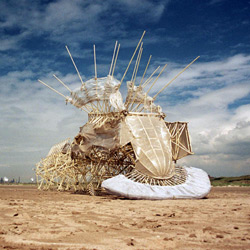
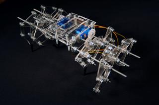
Small walking robot. This robot appears to be modeled after Theo Jansen's Strandbeests.
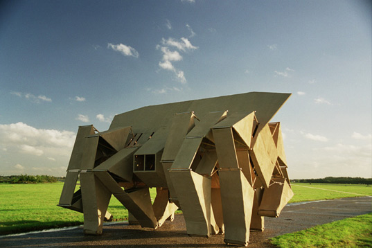
Mute Ant: a human powered walking machine. This contraption uses 4-bar linkages to simulate walking motion.

Ridable hexapod.
Linkages
Below are diagrams of the two linkages that I'm interested in: the Klann Linkage and the Jansen Linkage.
Klann Linkage. A 6-bar linkage with fairly smooth gait. Wikipedia has a good writeup on this linkage.
Jansen Linkage: this was developed by Theo Jansen for his Strandbeest project. The linkage has a smooth gait that, like the Klann linkage, is driven with rotary motion from a single point. The creatures were designed to be wind-powered, but can also be pushed or driven using other inputs. A good comparison of the Jansen Linkage and Klann linkage can be found here.
Below are some examples of these amazing creatures:
This is a video of Jansen's TED talk.
A wind-powered evolution of this beast.
This heavy version can be pushed by a single person or the wind.
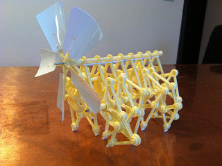
Toy version of a Strandbeest.
This is an open-source beta version of a Strandbeest. Included are plans for laser-cutting and useful videos about the workings of this machine. I think this would be a good place for me to start my research into the mechanics of this project.