Computer-Controlled Machining
This week's assignment was "make something big." I had a lot of ideas for this, ranging from large dragons (in keeping with my theme) to furniture. I drew inspiration from the two following images:

This rolling bookshelf looked really fun, but incredibly impractical for dorm living (It's almost as wide as my room and uses the space very inefficiently). I really like the idea of moving furniture by rolling it without separate wheels. This would both make transportation of the furniture easier and give bored dorm-mates something to play with.
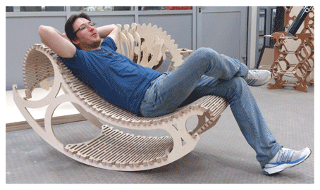
(from http://academy.cba.mit.edu/classes/computer_cutting/flexures.png)
I like the idea of using wood flexure (or "wiggle wood") to make curved furniture. The surface seems like it would be more comfortable than straight tab-slot construction because the surface is more continuous.
The final idea that I settled on was a rolling sofa. I realize that the idea isn't very practical, seeing as the sofa will roll over while you are sitting on it, but the idea sounded to ridiculous to pass up. The basic idea: make a sofa with 4' diameter wheels instead of the traditional armrests. Theoretically, I could roll it home from the shop (about a mile) rather than arranging for transportation. Plus, the idea of rolling a sofa end-over-end down the hall entertains me.
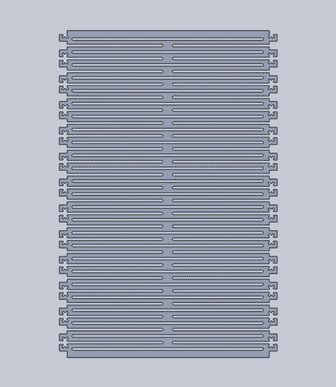
This serves as both my proof of concept (testing my flexure design before cutting a piece three times its size) and a support for the sofa. This is meant to run between the inner supports of the sofa such that they don't splay when weight is applied.
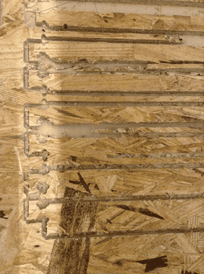
This was my first attempt at cutting a flexure. It did not turn out well. In retrospect there were some problems with this initial design (lack of dog-boning and sub-optimal order of cuts), but the main issue seems to be the material I was making it out of. Oriented Strand Board (OSB) is in ingenious waste-selling method but is not the most structurally sound material. It splintered to the point that I didn't feel it was worth finishing the cut- the edges were getting too maimed.

I imported my design into Partworks and created toolpaths. I ran into a few problems while doing this:
-dog-boning: I looked at various tutorials and just couldn't get it to work. I instead made a linear pattern of circular cut-extrudes in Solidworks, which ended up being much easier than the Partworks dog-boning methods anyways.
-Zero path thickness errors both when calculating with 1/4" and 1/8" diameter endmills for a .25" slot. I fixed this by milling on the line rather than inside, which ended up being okay for this support. I would not recommend this for the weight-bearing flexure of the sofa, as it significantly thins each section of the flexure.
-tool speeds: MAKE SURE TOOL SPEEDS ARE IN THE CORRECT UNITS. I broke a 1/8" endmill because of an error in traverse speed; bits do not automatically update between tool paths.
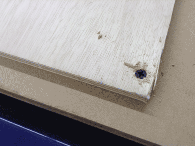
After setting up your toolpaths in partworks (and saving them), one is ready to prepare the material for cutting. The material needs to be fastened down tightly to the sacrificial layer of wood beneath it. Zero X and Y wherever you want to (I set my zeros in the bottom left hand corner of the Partworks canvas and the corresponding zero position on the shopbot bed, but moving the zeros around to use the material more efficiently is not a bad idea. Zero Z with the Z-Zero Plate in the "cuts" menu. Be sure to use the alligator clip and NOT to zero z with the zeroing plate on top of a screw or anything else not level with the surface of the material.
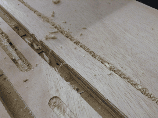
This is where my endmill started getting sad. Notice the buildup of shavings on the rights and the chatter in the upper left corner. There are two reasons for this. One: choose climb, not conventional milling, in the partworks toolpath dialogue box, for chip-clearing purposes. Two: make sure travel speed and spindle speed make sense together. My travel speed was too high compared to my spindle speed, so I broke an endmill. I turned up the spindle speed to 16.0 (16000rpm) to compensate for the travel speed. It worked, but the chips did not clear as well.
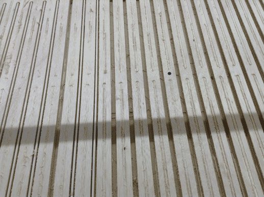
Approximately halfway through the first milling job.
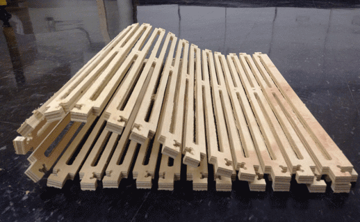
The moment of truth came when I took this off of the ShopBot. For some reason I was very skeptical as to the ability of this flexure plywood to bend an appreciable amount. I was very pleased to see this flopped response. More testing is needed to see if this thinning of wood adversely effects the weigh-bearing properties of plywood sheets in order to see how wide of a sofa I can make without collapse and with minimal supports.
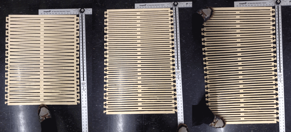
Again, I was pleasantly surprised by the flexibility of my flexure plywood. There was more than three inches of give in either direction, which, thankfully, means that the tabs on the ends of the sofa onto which the flexure will be fit won't have to have tight tolerances.
I didn't have enough time to finish machining the entire sofa (cutting stuff on the shopbot always takes longer than expected, especially when other people need to cut as well), but I have everything CADed that I need. I plan to continue cutting and constructing my project over the long weekend.
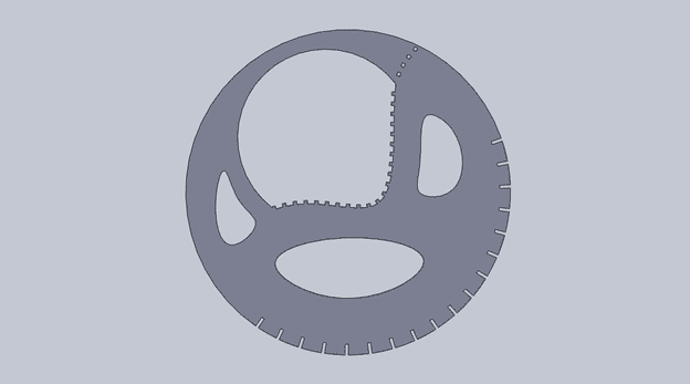
Sofa outer side (x2): the slits on the outer radius are places in which crossbars can be added, both to prevent splaying of the legs and to attach a small tab-slot rectangle to lock the sofa in whichever position you want it.
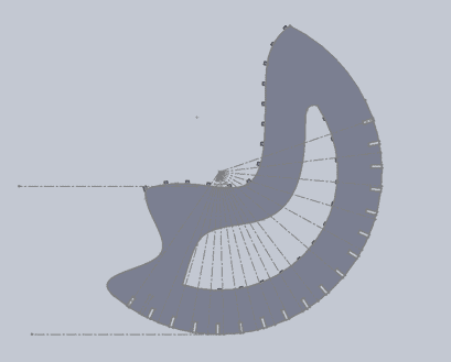
Inner support for the sofa (x2). The large flexure runs up the seat-like part and the other two ends either dangle or get shortened. The thinner flexure that I already made will run through the inner slot between two of these.