FabISP
This week I made a FabISP (Fab-able In-System Programmer) from the standard plan. Required machines: Roland Modela Desktop Mill and Soldering Iron.
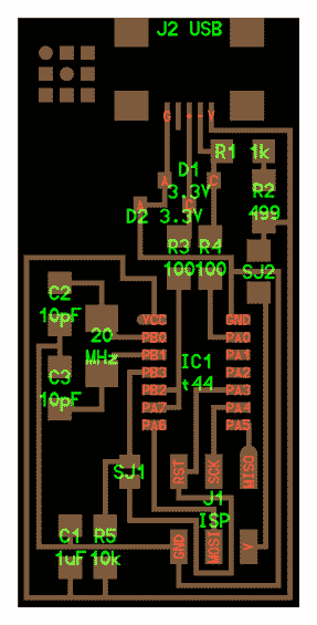
This is the circuit layout that I replicated this week. SJ1 and SJ2 are solder jumpers (SJ2 is a 0 Ohm resistor).
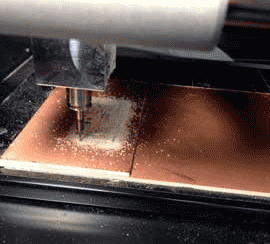
To use the mill:
1) Press "View" to put the mill in view mode and bring the bed forward if it isn't already.
2) Use double-stick tape to attach the circuit board to the sacrificial layer, pressing firmly. The circuit needs to be flat for even 0.1" milling.
3) Press "View" to put in run mode. The green light will turn off and the bed will move back.
4) Load the bit (1/64" for traces, 1/32" for cutout), using the hex key to lightly tighten it.
5) In the fab module on the computer, load the traces (.png). Settings: z depth to 0.1", 4 paths, 1/64" endmill.
6) Move to x_min, y_min. On the Modela position the tool height using the up/down arrows, until there is about a finger's width of travel left. Loosen the set screw, holding the endmill so it doesn't fall and break. Lower gently until the endmill touches the surface of the board, then tighten setscrew.
7) Make .rml. Send.
8) Repeat, but with 1/32" and cutout path.
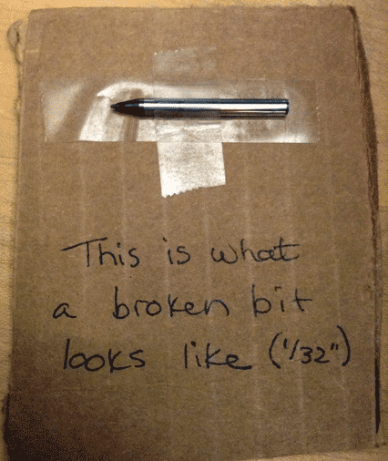
I ran into a bit of a problem with my settings on the cutout path. Don't accidentally set the z-depth too deep: the bit will shear.
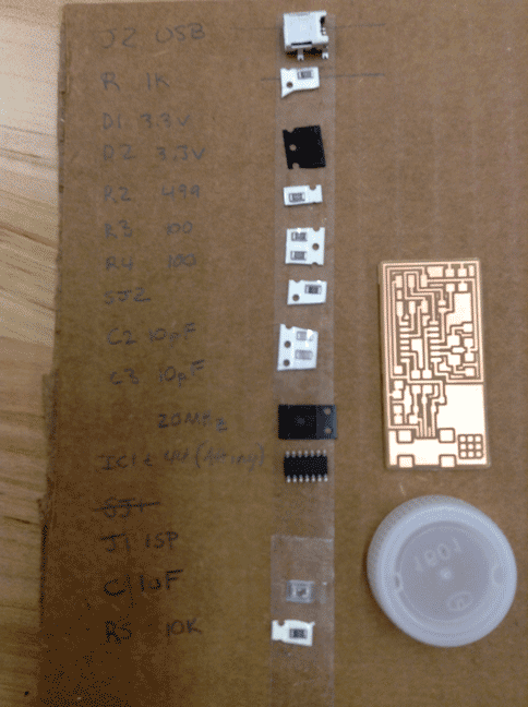
This is a picture of my milled circuit. I washed it with soap and water to remove small burrs and oils. This size of this circuit was a bit intimidating: I was not expecting the components to be this small. The water-bottle cap is for size reference. My TA gave me some awesome advice: write your list of components on a sheet of paper (I used cardboard because it was easier to find) and run a piece of double-stick tape beside it. You can then sort your components on the tape and quickly find the small pieces.
Stuffing the board: I don't have any pictures from this step. Lining the small components up was very difficult; electronics tweezers made this task slightly easier. Laying down a small tack bead and then lining up the component and remelting the bead worked well. The solder wicking braid worked better for me with the larger-tipped iron. Make sure that you aren't just melting the braid into the solder- I accidentally pulled a trace off when I got it stuck (quickly patched with more solder).
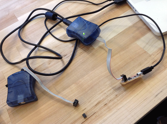
The newly stuffed board was then hooked up to a computer through one of these blue boxes and a ribbon cable. The firmware was downloaded to the ATTiny44. Amazingly, it worked on the first try! The log in the control panel reported a fuse error, but the firmware appears to be doing its job: when hooked up to USB the board shows up as FabISP.
Programming Steps (Command Line):
1) make clean
2) make hex
3) sudo make fuse
4) sudo make program
If everything worked correctly you should now see "FabISP" listed under Hardware and Sound in the Control Panel.
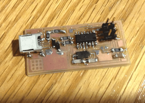
After the firmware is downloaded, the solder jumpers (SJ1 and SJ2) need to be removed.
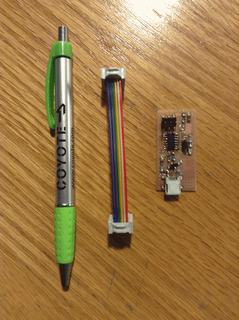
The next step was assembling the ribbon cable.
Tips:
-Use a vise to lock the headers together (with the wire in between them).
-Make sure that the wire is lined up correctly: the red wire should go to the same jaw of the connector on either end- there is a dot on the connector for reference.
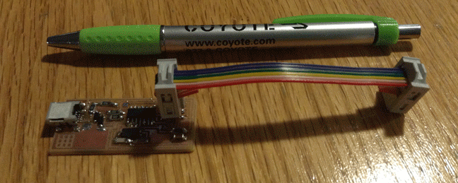
The finished circuit with my ribbon cable attached.