10. Input Devices
- Design Challenge: add an input device to a microcontroller board
- Software: avrdude,CrossPack,terminal,eagle
- Tool: FabTinyISP
- Date Completed: 11.21.17
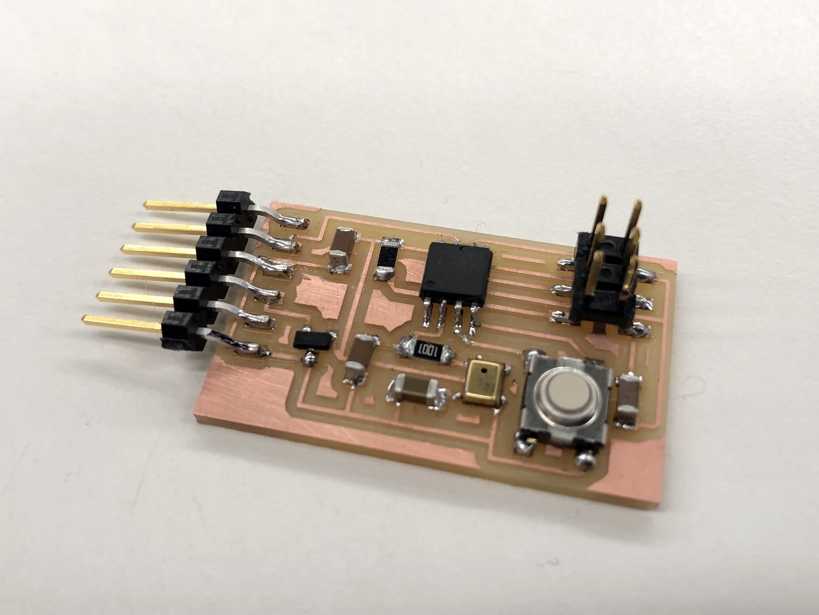
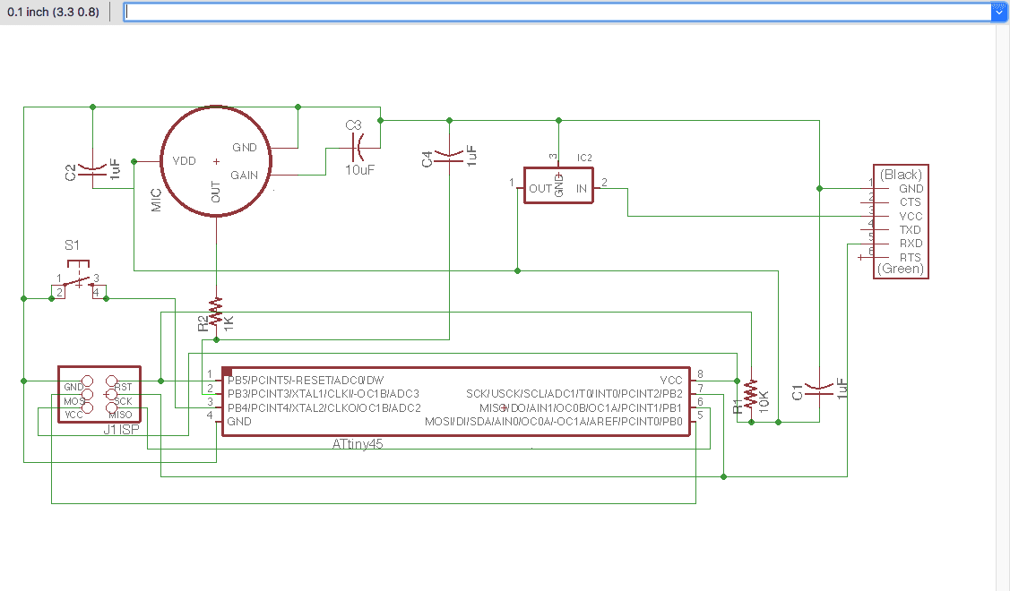
We are supposed to build a board and add an output device on the board this week. I am using a microphone to make a sound receiver. I choose the Analog MEMS Microphones and add it on the board with ATtiny45.
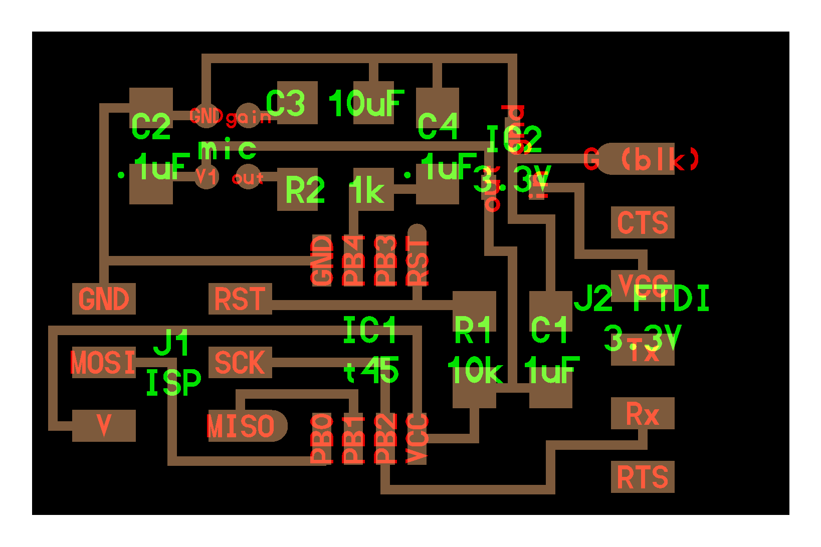
I design my board based on Neil's example. I add a button to the board. I hope to build a device that can record sound once I press the button, which I will be using for my final project.
We used straight bit this time.
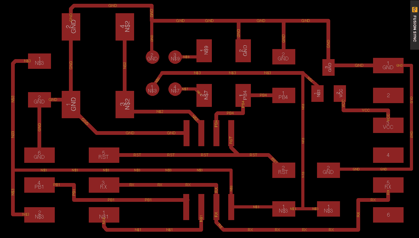
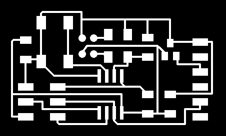
Then, I generate the board and route the wire.
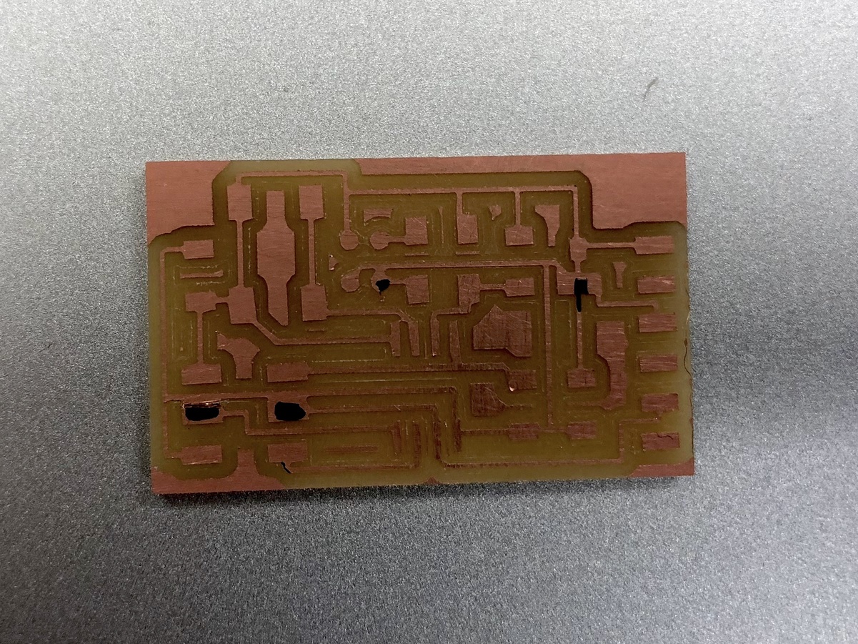
When I milled the board, I found that some components are connected. I checked the schematic and find out these are the parts that have less than 15 mi distance in between.
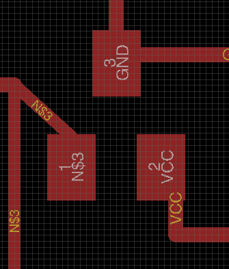
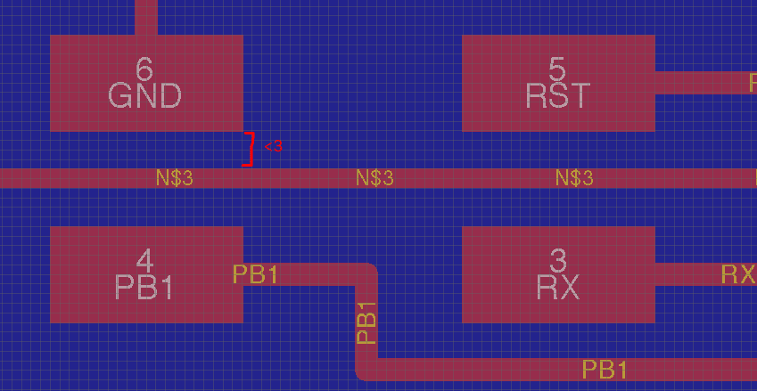
Then, I modify the route, and make sure to leave enough space in between.
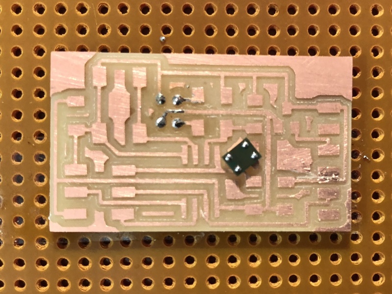
It was really hard to solder the microphone. I put solder on the board and microphone. Then, I used heat gun to heat the solder in order to reflow solder the piece.
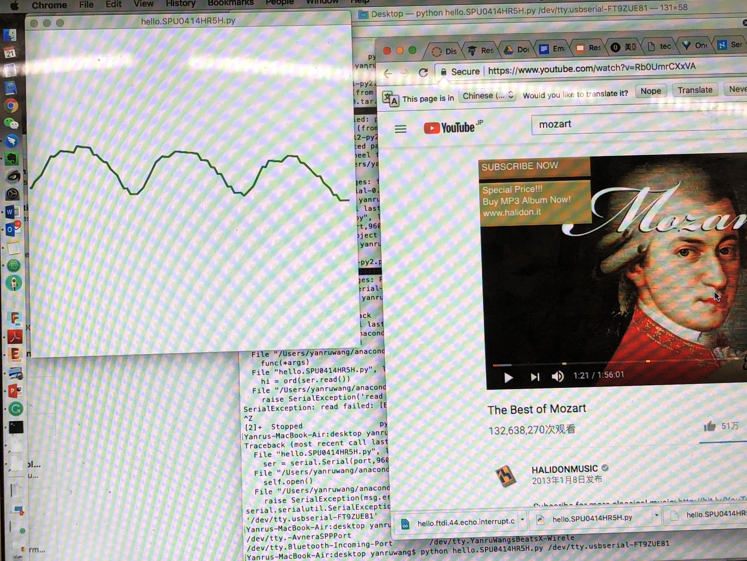
At first, I tried with Neil's code. I embeded the code to the board and run the python program.
In order to run the python program, we need to pip install PySerial to download python serial. Then,
run ls /dev/tty.* . Copy the last name of the file (FT9ZUE81 in this case) that is generated by the command.
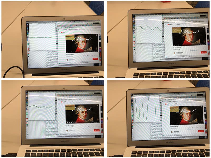
Run python hello.SPU0414HR5H.py /dev/tty.usbserial-FT9ZUE81 to open the sound sensoring window above.
Yeah, it detected the sound!
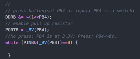
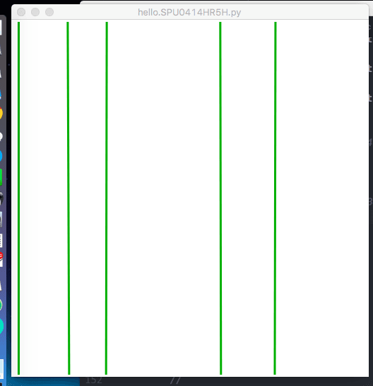
I tried to active the button. I want to use button to control whether to record the sound or not. I add the following code. It didn't work. It ended up giving me vertical lines.