2. Electronics Production
- Design Challenge: Building the FabTinyISP
- Software: N/A
- Machinery: Milling Machine Roland SRM-20, Soldering Iron
- Date Completed: 09.25.17
PCB Fabrication
It's milling
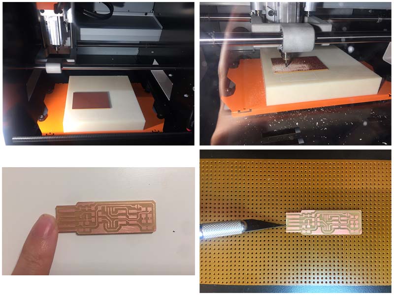
- Top left: adjusting the endmill- be very careful, do not drop the ennmill!
- Top right: start milling - make sure the board doesn't get removed from the cutting
bed and the it is cutting the whole board without missing any pattern.
Download the PNG files for the traces and the board outline here. - Bottom left: clean the board!
- Bottom right: remove a tiny bit of copper at the edge of the board.
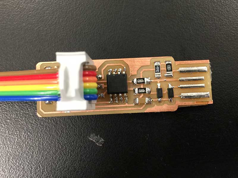
Assembling the PCB
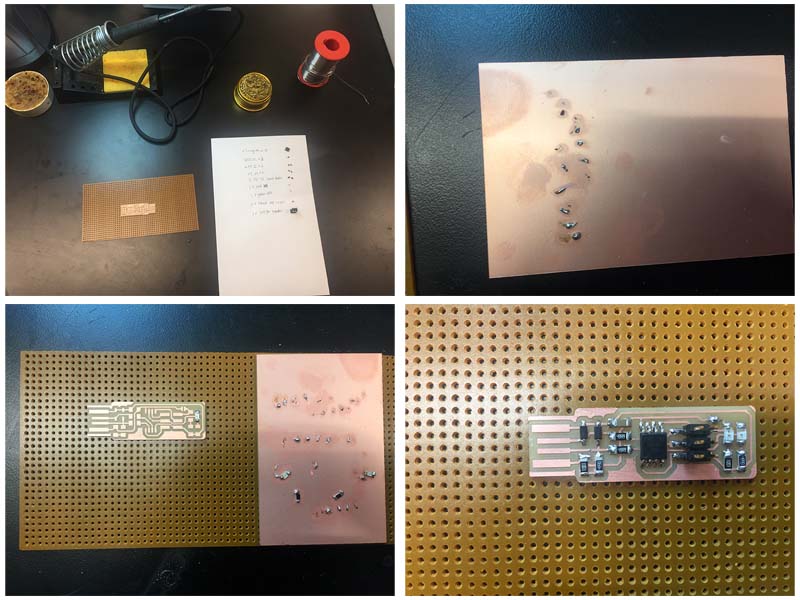
- Top left: Obtain the components
- 1x ATtiny45
- 2x 1kΩ resistors
- 2x 499Ω resistors
- 2x 49Ω resistors
- 2x 3.3v zener diodes
- 1x red LED
- 1x green LED
- 1x 100nF capacitor
- 1x 2x3 pin header
- Top right: I practiced soldering on an empty board before starting.
- Bottom left: Soldered the parts to the PCB and used the schematic and board image below as a reference for component values and placement. I started from one side to the other and smaller components to the larger ones. Be careful with the direction!! detailed instructions here
- Bottom right: remember to create a bridge on the jumper near the ISP header when you done soldering.
Program the ATtiny45
*I did all the following steps with Rob’s help. Thank you!
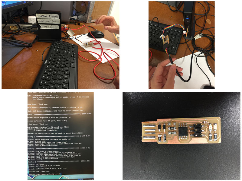
- Top left: the red LED lights when the target circuit when I plug in the board. Then, I ran make flash to the board.
- Top right: ran the make fuses command, the green LED was flashing when the programmer is talking to the board.
- Bottom left: ran make rstdisbl command.
- Bottom right: disconnect VCC from the Vprog pin on the ISP header by removing the bridge on the solder jumper.
Things I LEARNT (not) to do
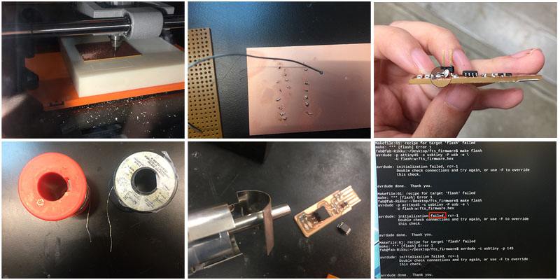
- Top left: my endmill was not touching the board, so it was not cutting the other side of the board.
- Top middle:I was not able to get the melted solder blob off the wire at beginning.
- Top right: one side of my ATtiny45 joints was not connecting to the board, so that failed to connected board to computer when I first tried.
- Bottom left: I used a thicker wire at the beginning and it was really hard by creating a large amount solder.
- Bottom middle: I didn’t pay attention to the orientation and soldered zener diodes and zener diodes in wrong direction. I had to use hot air gun and braid to unsolder.
- Bottom right: My board was not connecting since of side of my ATtiny45 was not connecting to the board.