12. Networking and communications
- Design Challenge: Design and build a wired &/or wireless network connecting at least two processors
- Software: Arduino IDE, Eagle
- Date Completed: 12.5.17
Design the board
This week we are supposed to design and build a wired or wireless network connecting at least two processors. I started with Neil's board first, and then I want to add more slave board to the master.
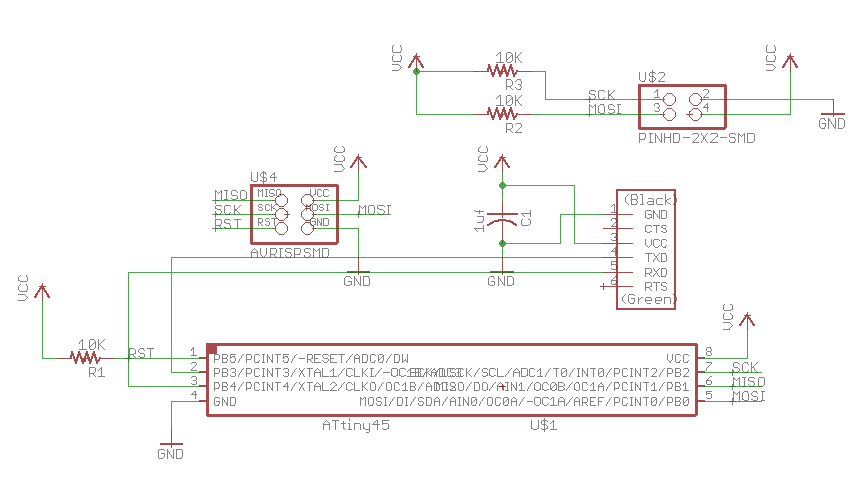
This is the schematic of master (bridge) board.
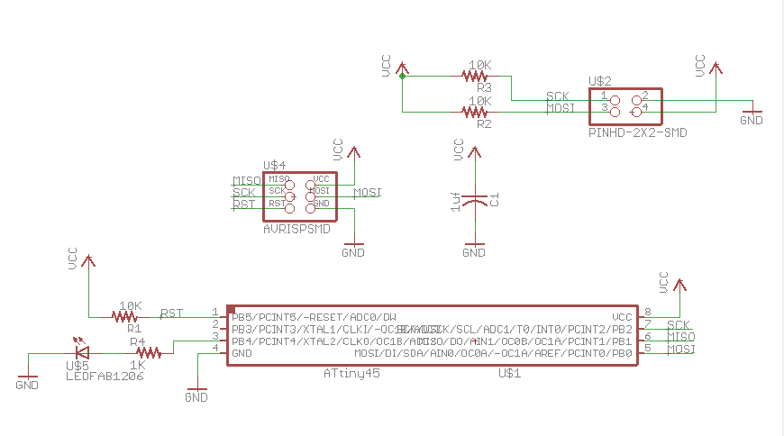
This is the schematic of slave(node) board.

Although I have used milling machine many times this semester, I kept running into issues this week.
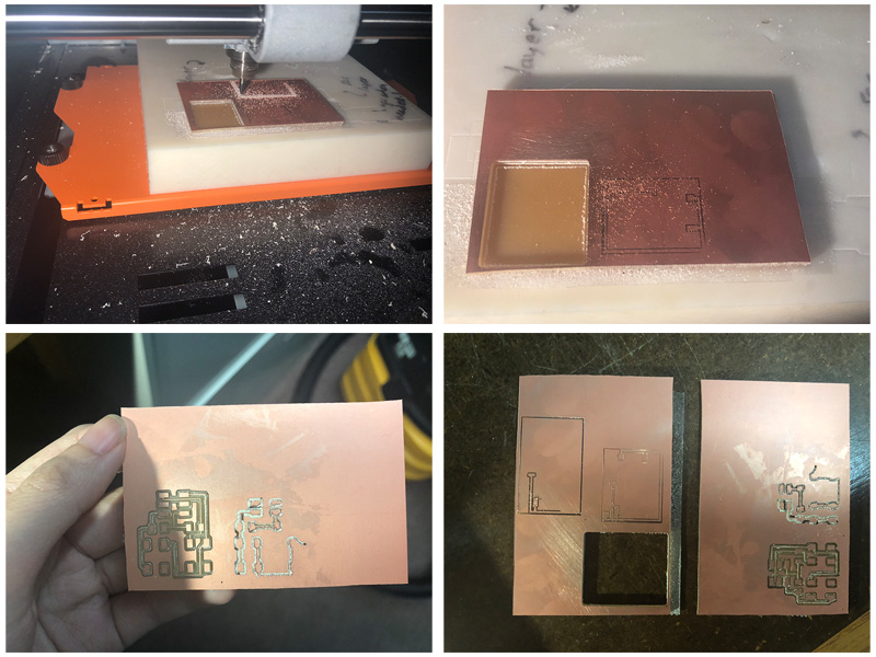
My board moved from its original position during milling, and I had to quit the machine.
Then, the bit failed to mill the board entirely. I took a very close look at the bit and found that it wore out.
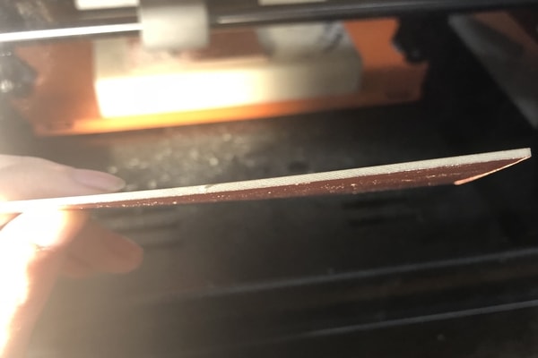
The uneven sacrificed board was another reason that caused bit failing in milling the board evenly.
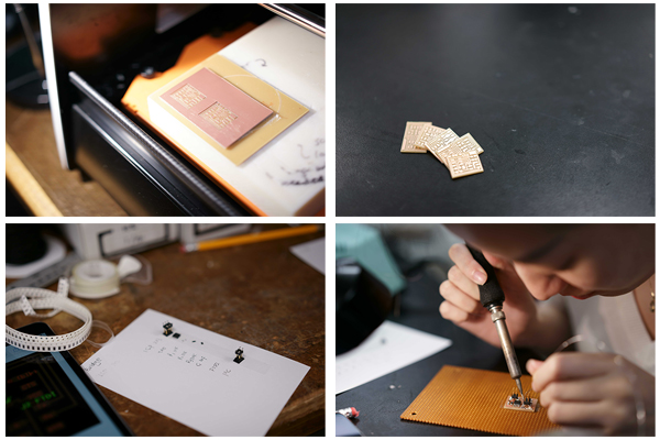
Soldering the board: there are many boards to solder this week.
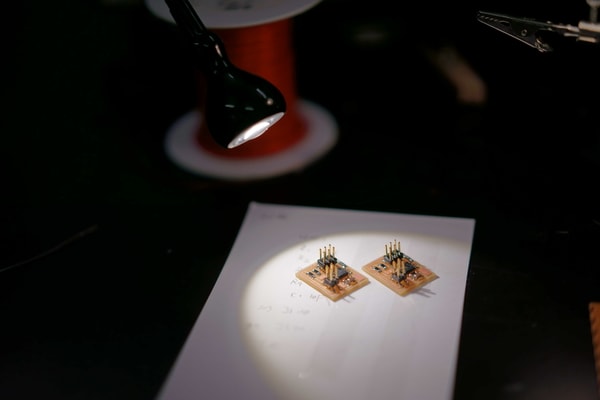
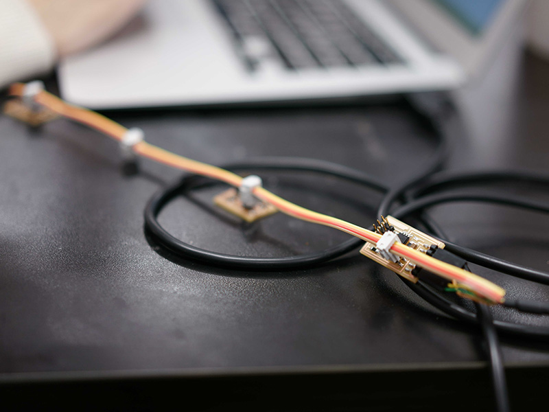
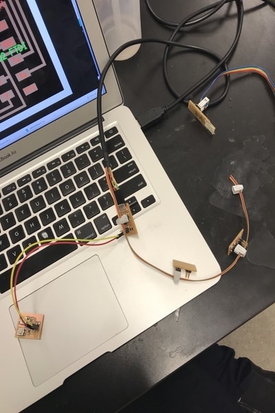
Finish soldering! These is a pair of slave boards. I am going to program these boards.
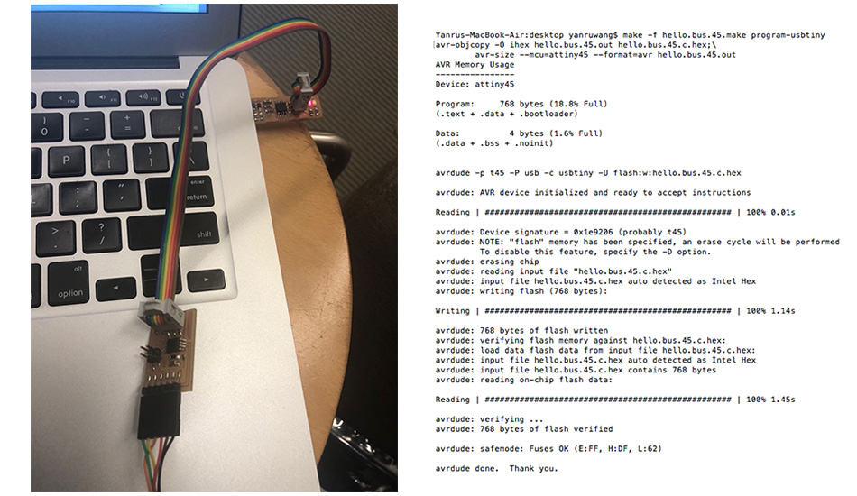
I programmed the master board first, and it went successfully.
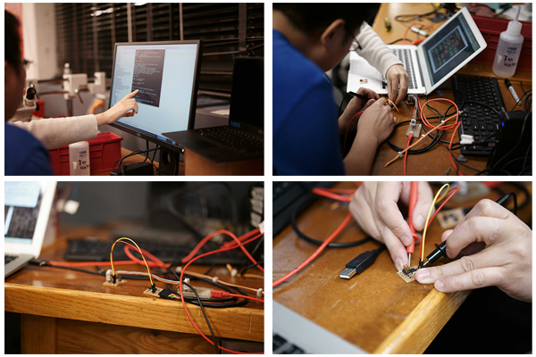
However, when I try to program slave board, I could not get the board to connect to the computer. We made sure that it is powered up by the master board by measuring the voltage on the board. Then, we decided to use jump to connect the slave board instead of the cable. It worked!
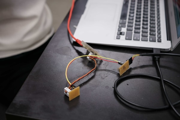
I decided to give it another try using cable, and somehow it worked this time.
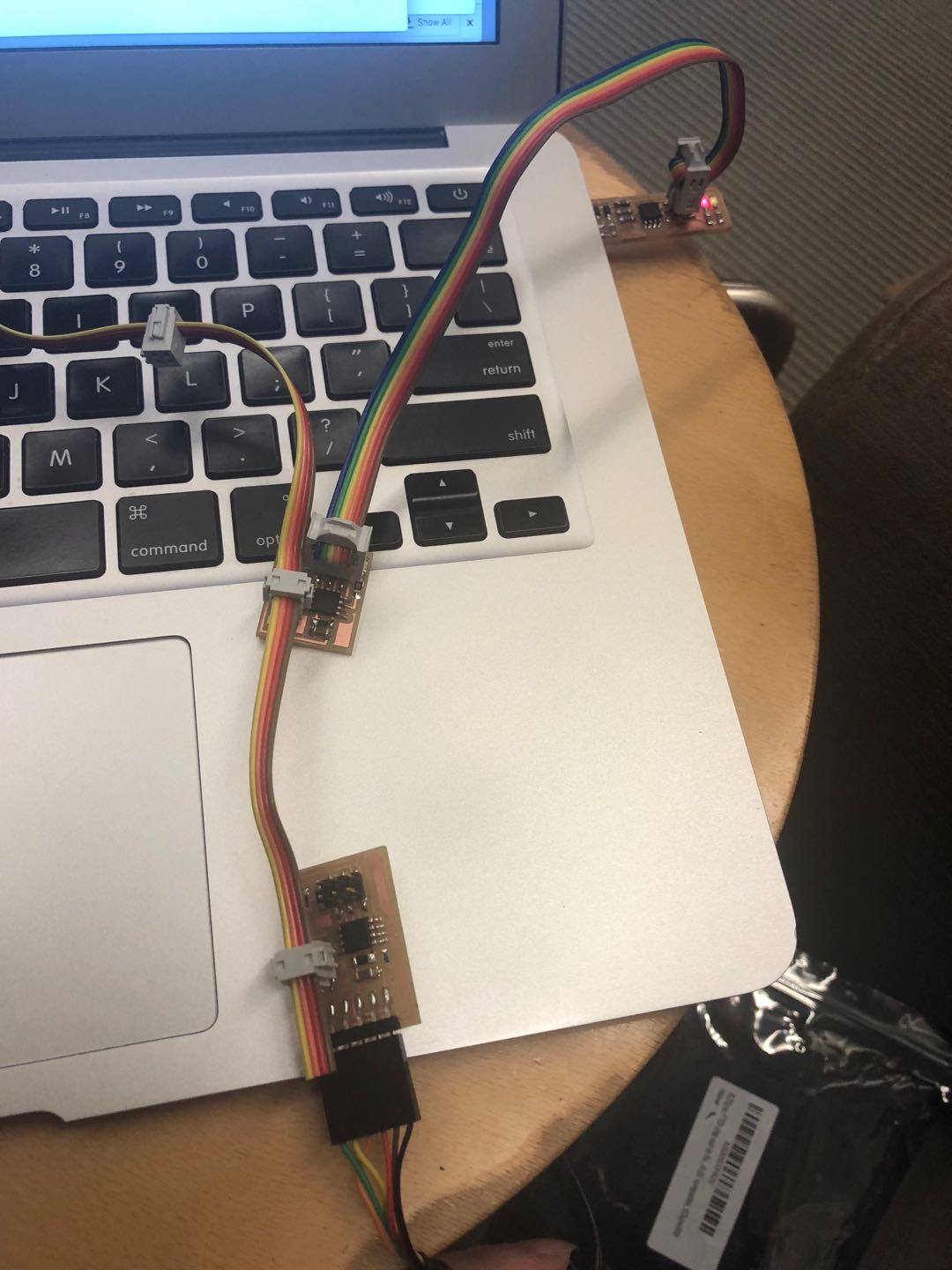
I programmed both slave boards. The LEDs blink!
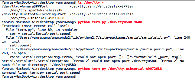
I want to run the code and see if all the boards are communicating with each other successfully. But I had trouble open term.py to run the program.
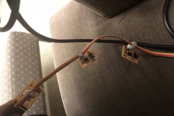
Adding switches
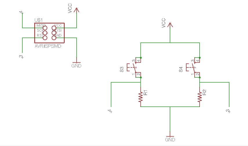
I tried to use two swithes to talk to the master board, and then control the led board.
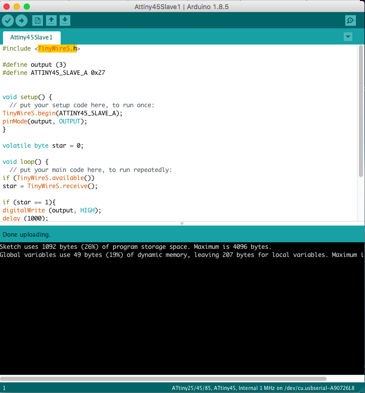
These is my first time try to program with arduino. I uploaded this arduino programto the slave board and this programto the master board.