4. Electronics Design
- Design Challenge: redraw the echo hello-world board, includes a button switch and LED light
- Software: Eagle, CoolTerm
- Machinery: Milling Machine Roland SRM-20, Soldering Iron
- Date Completed: 10.10.17
PCB Design
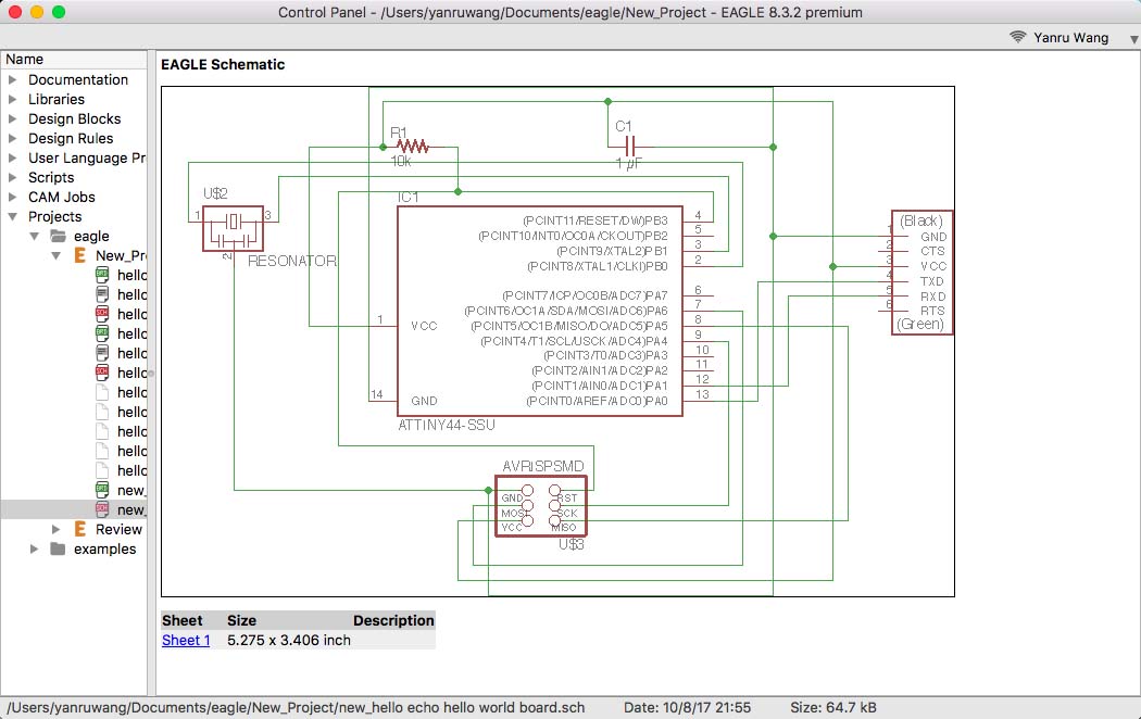
I chose eagle to draw the circuit borad. The necessary information to draw the echo hello world board are gathered on the class page. I am adding follow components to my circuit:
- 6-pin programming header: for programming the board
- Attiny44A microcontroller: the 'brain' of the board
- FTDI header: powers the board and allows board to talk to computer
- 20MHz resonator: external clock, the internal IC clock is not 100% exact
- Resistor 10 kΩ: adjusts current
- Capacitor 1 µF: stores charges
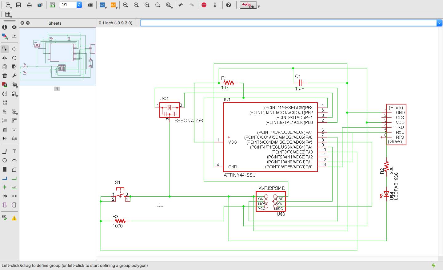
Then, I am adding a switch and a LED with the corresponding current limiting resistor to the circuit. According to datasheet, the operational voltage for ATTiny44 is 5.5v. The LED current is typically around 20 mA, by a Voltage drop of approximately 1.5 V. Following Ohm's law is my resistor then 200 Ω. Since there is no 100 Ω at Harvard shop, I picked 100 Ω.
- Button: to switch on and off
- Resistor 10 kΩ: adjusts current
- Resistor 100Ω: adjusts current
- Capacitor 1 µF: stores charges
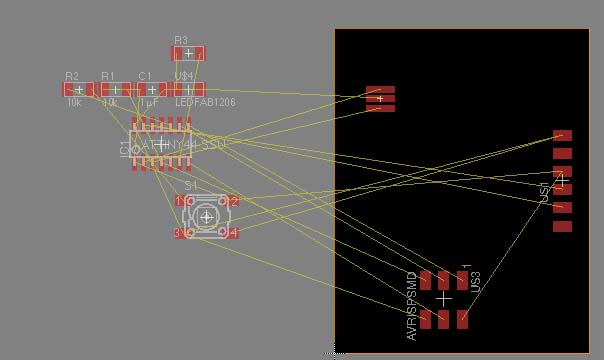
I convert my schematic to board when I done design and check the connection. Then, I start to connect trace based on the design. Be careful with the closed line, because the mill will not be able to cut it correctly if the traces are too closing.
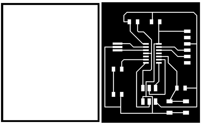
Before I can mill the board, I have to export as a png. I created both trace file and outline file. I chose 500 dpi when export the file and select monochrome.
Milling the board
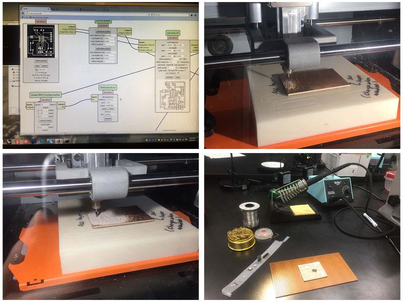
- Top left: Check the size of the board before printing, it should be within 1.5inchies to 2inches.
- Top right: Using 1/64 millend to print the trace.
- Bottom left: It is actuclly printing very well.
- Bottom right: I am ready to solder.
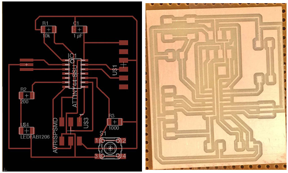
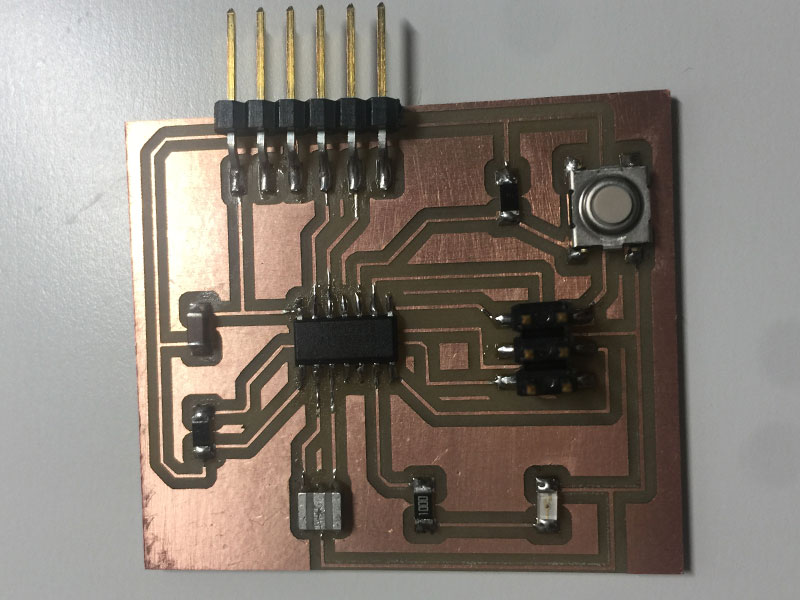
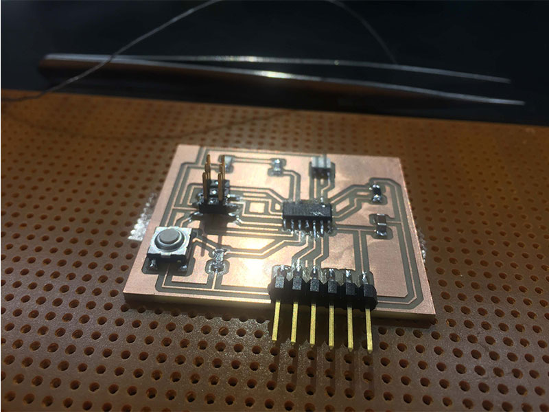
A comparison of my design and the actual printed board.
Soldering
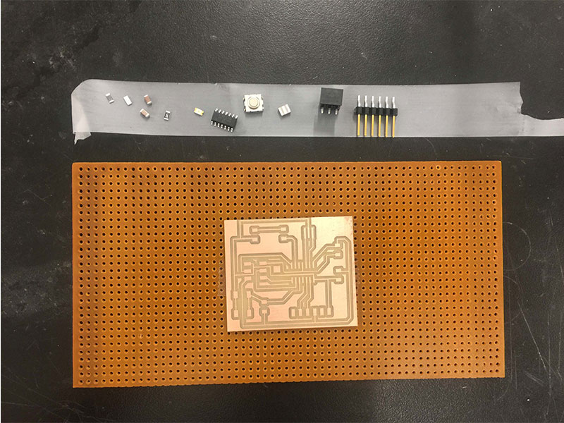
I have all the components and ready to soldering. I am very careful with the direction of LED and microcontroller, since I made mistake last time.
It only took me 20 minutes to solder the whole board. I am getting really good:) But I find that my external clock was not connecting to the ATiny44 when I ran the code later on. I had to come back and re-solder the connection of external clock and ATiny44.
Program echo hello-world board
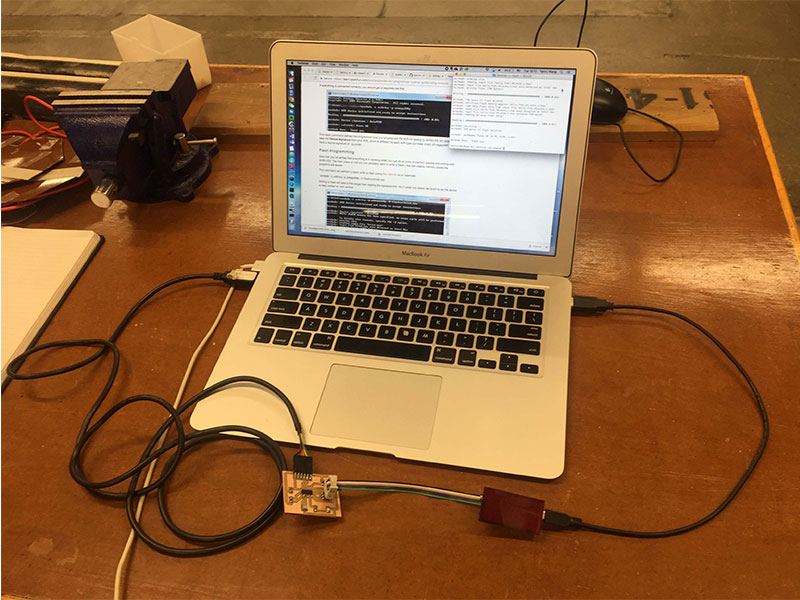
I used programer USBtiny from week 2, connected it to the programming header of my hello world board. And power the hello world board with 5.5v FTDI Cable.
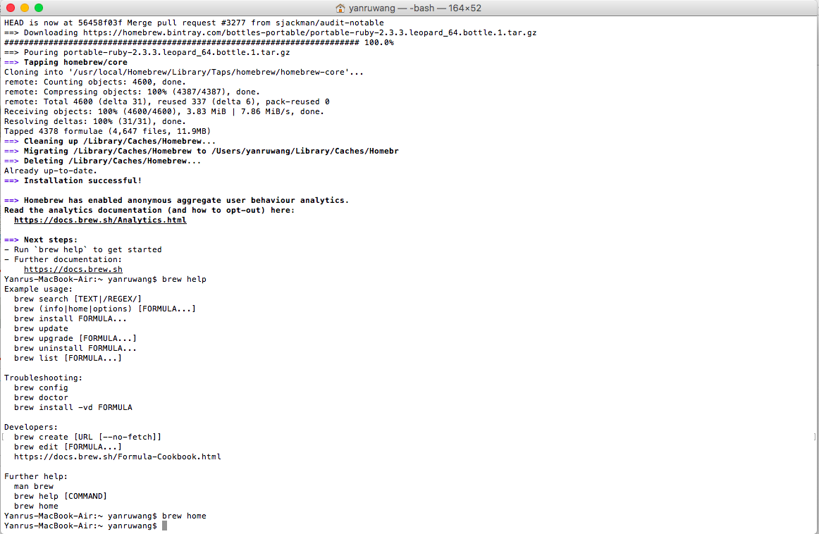
I downloaded the CrossPack for AVR® Development here and installed in my MAC with the instruction here. Then, I ran the code with the downloaded hello.ftdi.44.echo.c and hello.ftdi.44.echo.c.make files following the instruction here.
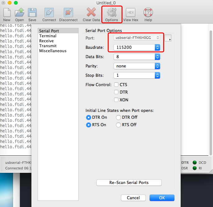
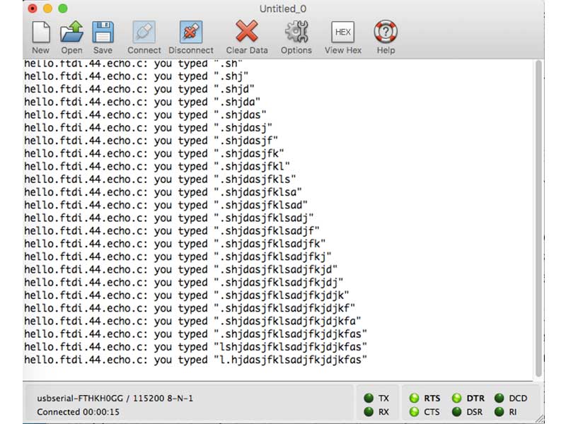
I downloaded CoolTerm here, and test if my board function correctly. Rob helped me connecting my board to my computer by changing the options in CoolTerm. I am really excited to see my board are running perfectly!