Hello World Board
Step 2: Draw the schematic following the steps outlined in the KiCad demo video but using the fab library components listed below and the layout shown in this schematic. I used the following components from the fab library:
- ATTTINY44-SSU
- AVRISPSMD: 2x3 pin header
- FTDI-SMD-HEADER: 6 pin header
- 6MM_SWITCH: button
- Resonator: 20 MHz
- RES-US1206FAB: 2x10k + 1x499
- CAP-US1206FAB: 1uf
- LEDFAB1206: blue
Pro tips: To reduce the number of wires in your schematic, you can add labels to the wires, and all same-labeled wires will be considered connected (Figure 5a). When you draw your PCB edge cuts, make sure you leave more space than I did (Figure 5b) between your outer traces and the edge of the board. Also, I forgot to leave extra space by the FTDI header so that the black part rests on the board, reducing mechanical load on your soldered joints.
Step 3: Export your traces and edge cuts for milling!
Step 2: Solder the components to your board./p>
Pro tips: The 6 pin header comes in [seemingly endless] lengths of pins; count carefully and break off 6 pins worth. I used a business card and double sided tape to keep my board and components in place (Figure 5d). For the LED, the cathode line points toward ground. As much as I researched and triple-checked before soldering, I still managed to place it on backwards. Also remember that your ATTINY is directional! For the resonator, I found it easiest to cover the middle footprint with solder first, place the resonator, then solder the outer footprints. Otherwise, the middle footprint can be difficult to access. If, like me, you solder everything on THEN realize you're missing a trace, you can solder a small piece of loose wire in its place (Figure 5e).
Total time: 7h
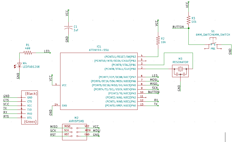
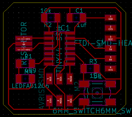
Figure 5b
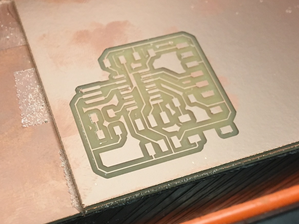
Figure 5c
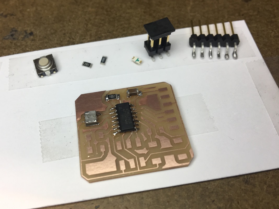
Figure 5d
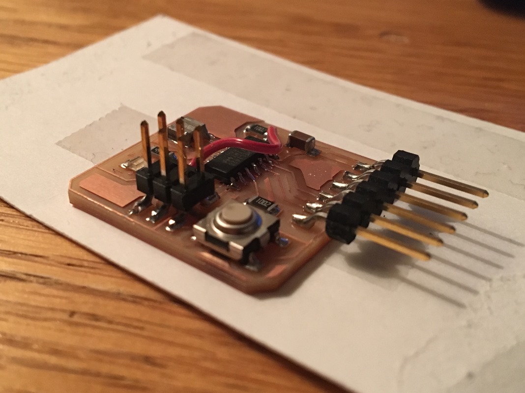
Figure 5e