Machine Design
- ATTTINY44-SSU: microcontroller
- AVRISPSMD: 2x3 pin header to connect programmer
- PINHD-2X3-SMD: 2x3 pin header to control up to 2 servos
- PINHD-2x2-SMD: 2x2 pin header for power
- AMS1117-5.0: 5V regulator
- RESONATOR: 20 MHz
- RES-US1206FAB: 10k x 2
- CAP-US1206FAB: 10uF
Pro tips: Note that there are two different 5V regulators in the fab inventory that have the same footprint but different orientations of voltage in, out, and ground. The hello.servo.44 board is created for a ZLDO1117 whereas the hello.servo.44.1 board is created for a LM2940. As always, make sure you leave 2-3mm between your outer traces and the edge of the board, increase the track width from 0.25mm to 0.4mm, perform a design rules check, and shift some of the not-to-be-exported PCB text so that it spills beyond the edge cut so that no edge cuts accidentally disappear in mods. Next time, I'll need to space out my board a bit more and make sure I have minimum clearance of 0.4mm; I found when the board was milled, multiple tracks and pins had joined, and both Nathaniel and I spent a good chunk of time slicing copper to separate them.
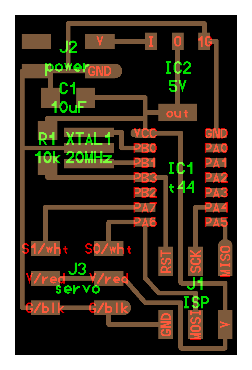
Step 2: Export your traces and edge cuts for milling! I added some text as well to help differentiate from any other boards being made this week.
Step 2: Solder the components to your board.
Step 3: Wire a button to the microcontroller side of your resistor and ground.
Step 2: Read this short and sweet wiki on servo control and pulse-width modulation. This was key in helping me understand what Neil's code was doing. Since we only needed the servo to rotate between ~135 degrees at the press of a button and return to position at the release of the button, I only kept the two chunks of code that moved both servos (if two are connected) to their "non-neutral" positions (1 ms and 2 ms), and I changed the 2 to 2.5 ms to increase the range of motion.
Step 3: Read this super helpful tutorial on how to turn on an LED with a button. I used the button_44_c.c code to supplement Neil's servo code with additional code that accommodates an input (the button). Here's my final servo code.
Step 4: Connect the board to your programmer AND to power.
Step 5: Open a terminal in the folder with the saved files and run "make -f hello.servo.44.2.make ProgrammerName." The relevant programmer name can be found in the makefile.
Pro tips: After getting a better handle on what was going on in the c code, I realized, at least for my purposes, it may have been easier to use Neil's hardware PWM c code and makefile, but I don't think it's a big deal.
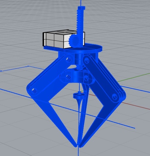
Step 2: 3D print it!
My hello world PCB
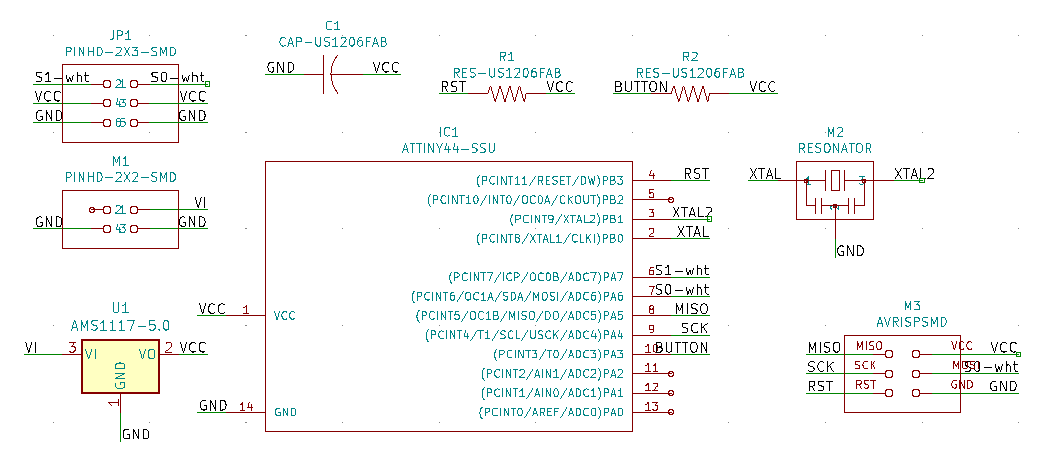
My servo schematic
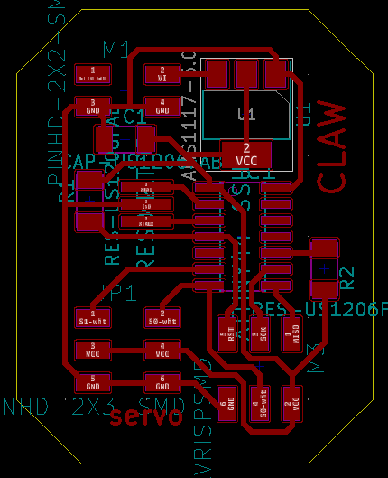
My servo PCB
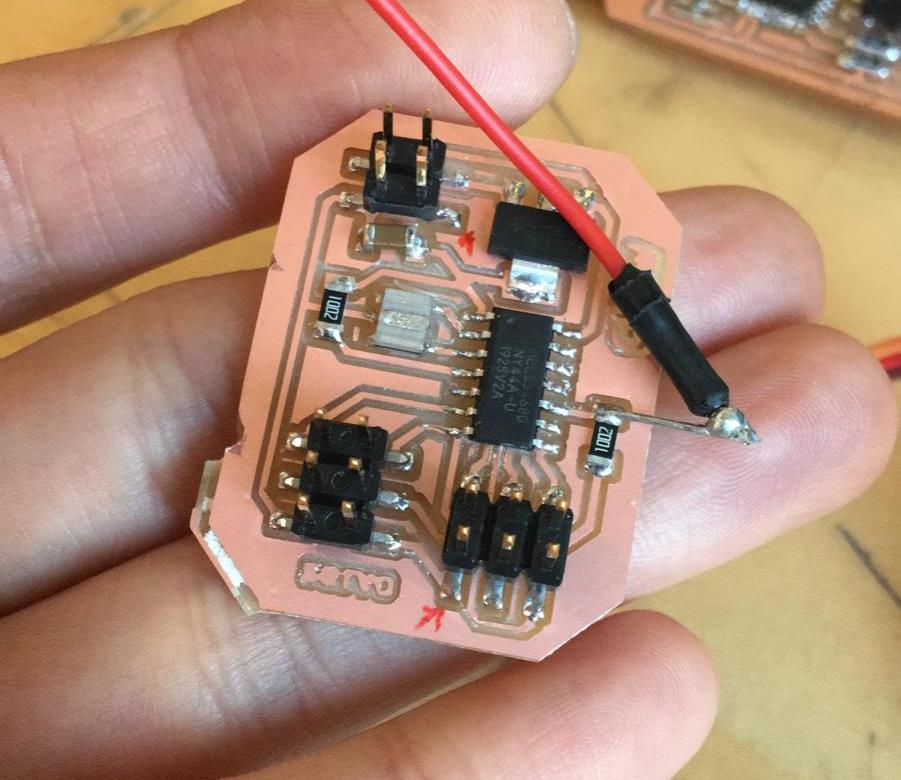
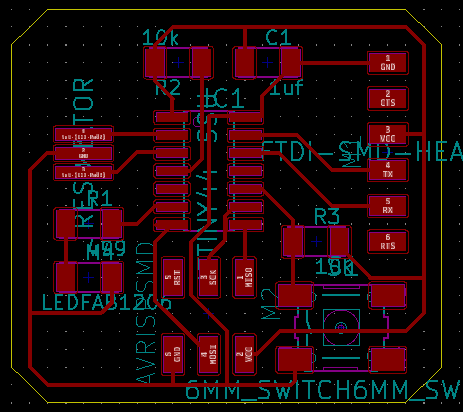
Final servo board
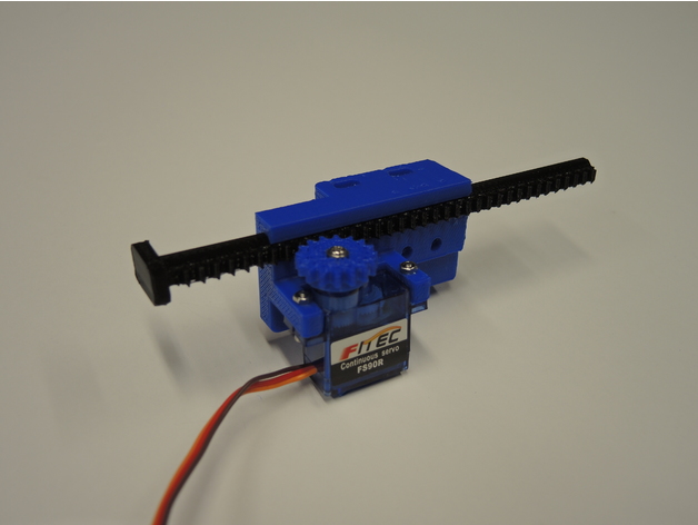
Linear servo actuator