Input devices
Turbidity meter
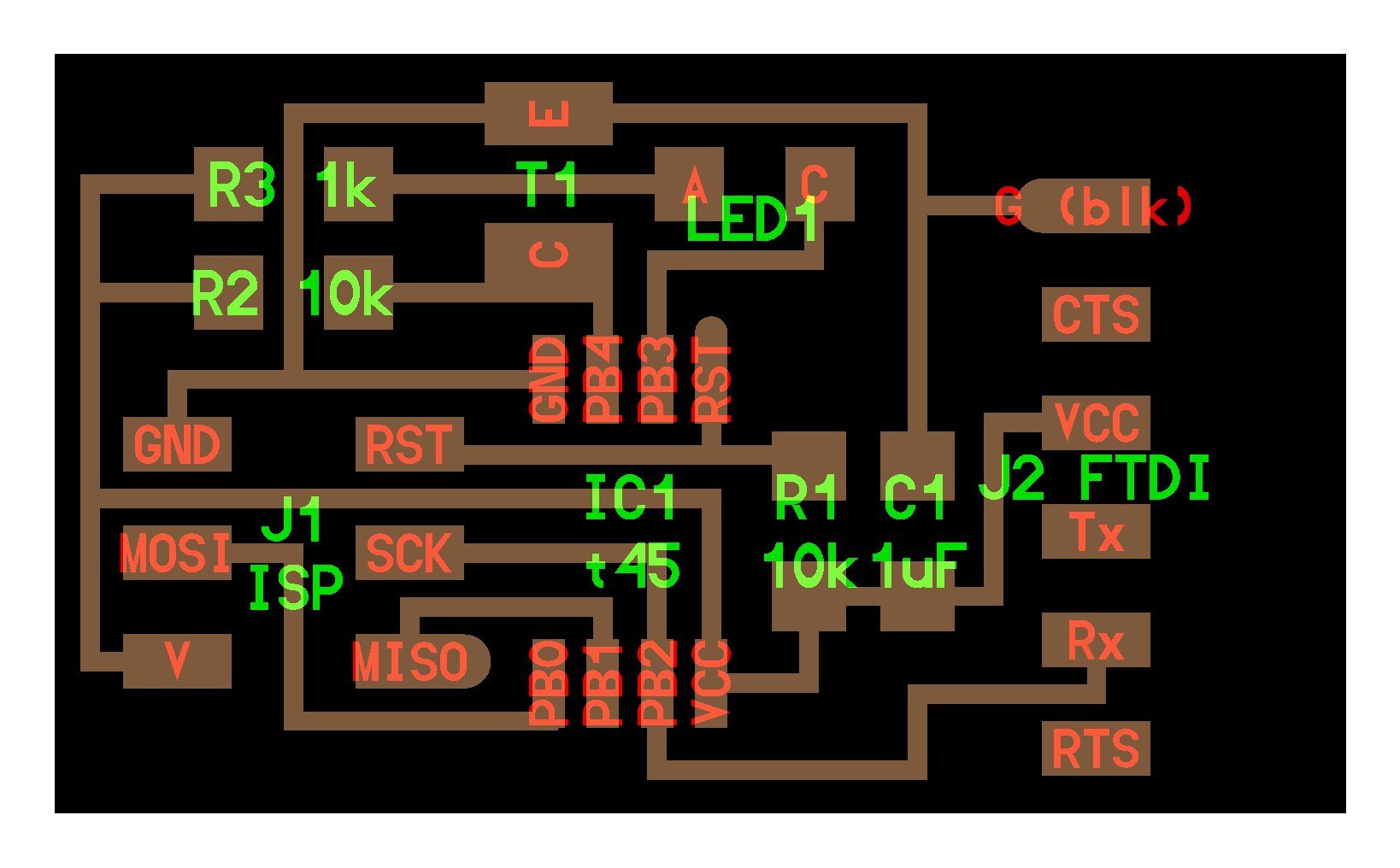
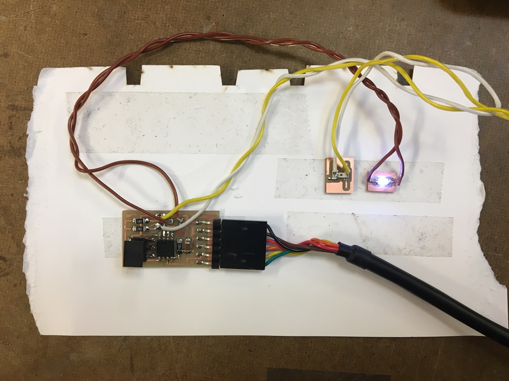
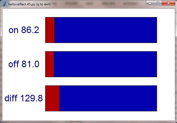
To ensure changes in ambient lighting do not interfere with readings, I decided to try my hand at Neil's synchronous detection board. I drew separate mini boards for the LED and phototransistor, so that 1) I could place them in water without immersing the whole board and 2) I could place them at right angles to each other as suggested in the references above.
- Current should only run continuously through two ends of connected wire. I had learned to use the multimeter during electronics production to to make sure things were connected or not connected appropriately. I thought anything that was connected should produce a beep from the multimeter. This week, I learned that current should not be running continuously across components, so when I held the probes on each side of my LED, the beeping multimeter was telling me I had a short. I couldn't see the short, but Alexandre suggested it was because I had both my wires entering the mini LED board from the same direction. In his words, "It was designed to fail." Needless to say, I re-milled the mini board.
- I technically could have used an IR LED and IR phototransistor and skipped the whole synchronous detection bit entirely. The IR LED and phototransistor would filter out any visible light, and therefore, changes in ambient lighting wouldn't affect the readings.
- The make command is "make -f FileName.make ProgrammerName." For some reason, I had been trying to run "make -f FileName.c.make" since electronic design week, which is probably why it wasn't working for me.
For my final project, since we are looking to measure small changes in light intensity due to turbidity, I may need to play with the intensity of the light or the sensitivity of the phototransistor; otherwise, the phototransistor is likely to be saturated by the LED, regardless of small changes in turbidity. It may also be possible to tune the sensor by adjusting the angle of the phototransistor relative to the LED.
Total time: 10h