Output devices
Step 2: Draw the schematic following the steps outlined in the KiCad demo video but using the fab and connector library components listed below and the layout shown in the photos. I used the following components from the fab and connector libraries:
- ATTTINY45SI
- AVRISPSMD: 2x3 pin header
- FTDI-SMD-HEADER: 6 pin header
- Conn_01x04_Male to OLED (SSD1306); use footprint Connector_PinHeader_2.54mm:PinHeader_1x04_P2.54mm_Vertical_SMD_Pin1Right
- RES-US1206FAB: 3x10k
- CAP-US1206FAB: 1uf
Pro tips: To reduce the number of wires in your schematic, you can add labels to the wires, and all same-labeled wires will be considered connected. When you draw your PCB edge cuts, make sure you leave 2-3mm between your outer traces and the edge of the and 7-8mm by the FTDI header so that the black part rests on the board, reducing mechanical load on your soldered joints. I would also increase the track width from 0.25mm (too thin) to maybe 0.4mm. Don't forget to perform a design rules check to make sure everything's connected.
Step 3: Export your traces and edge cuts for milling!
Step 2: Solder the components to your board.
Pro tips: The feet for the male header were too long for my footprints, so I snapped the ones that would create a short in half.
Step 2: Connect your board to your programmer AND to power. No need to connect the OLED yet.
Step 3: Open a terminal in the folder with the saved files and run "make -f MakeFileName.make ProgrammerName." The relevant programmer name can be found in the makefile.
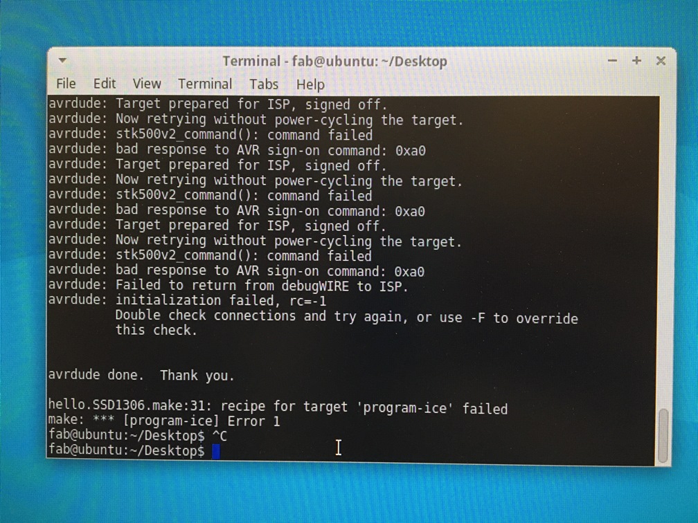
Pro tips: The RPL computer is real finicky. Find a way to use your own. I got lots of errors, but mostly it was because the computer was either not believing that it was connected to the programmer or not believing the OLED board was connected to power.
Total time: Too many hours
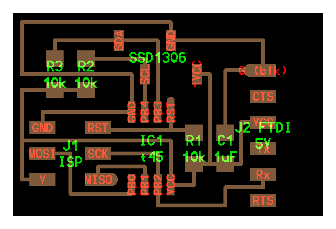
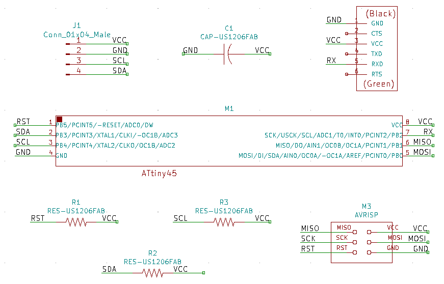
My KiCAD schematic
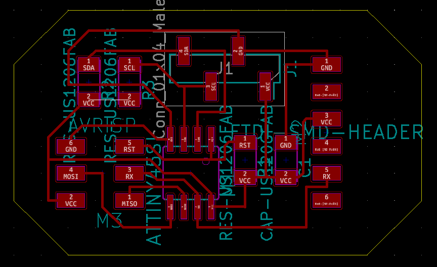
My OLED PCB
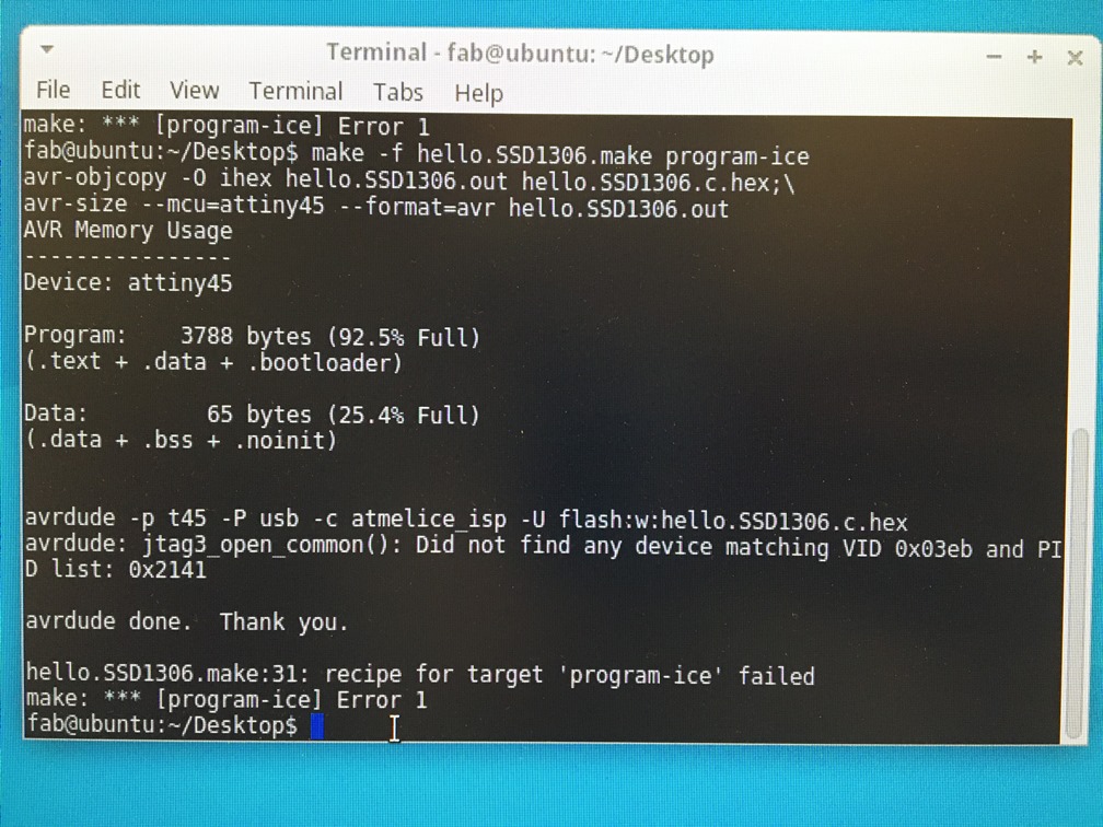
Error: Atmel ICE disconnected
Error: Total mystery
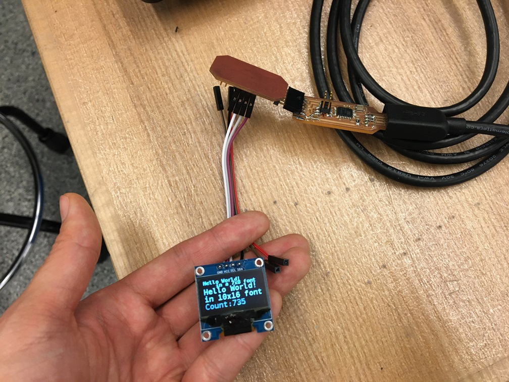
Working OLED