Printed circuit board
Characterizing the design rules
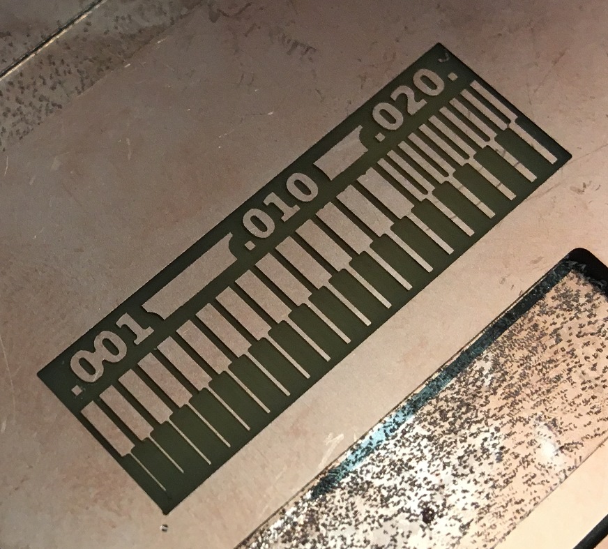
We started off all wrong with the characterization. Thinking, mistakenly (and in retrospect, illogically), that we were supposed to use the 1/32 and 1/64
end mills for the characterization, we went about milling the image provided with the 1/32 end mill. The result was laughable. From there, we figured
it out and got a much nicer result using the 1/64 end mill (Figure 3a).
Making the board
Milling the board was straightforward because Paloma demonstrated the process for us, but I could've used a more full-on soldering demonstration.
Oral descriptions and diagrams really wasn't cutting it. So I suffered through what I theoretically understood of the tacking method, botching it
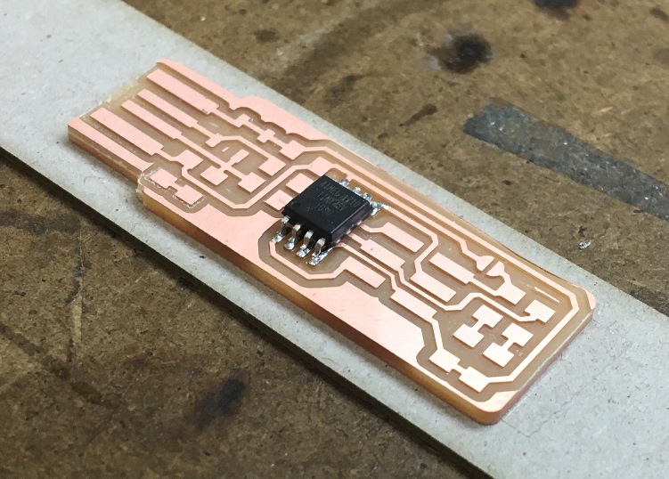
repeatedly, until Anna came along and played the part of my third hand and, more importantly, voice of reason. We made it through about half the
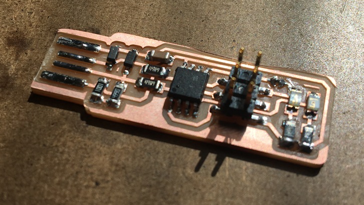
components pretty successfully with three hands (see first celebration of progress in Figure 3b), which is when Diego saved the day by showing us how
to properly tack. See completed board in Figure 3c.
Programming
I ran into a couple problems programming, which were solved by 1) restarting the computer, 2) making sure the devices were connected to the Linux OS
and not Windows, and 3) adding more solder. What I found more frustrating was trying to break the bridge once programming was complete. I found using
the braid was not intuitive, but in the end, I was successful by laying the braid perpendicular to the board like a knife, and putting the soldering
pen directly onto the solder.
Total time: 7.5h
×
![]()
Figure 3a
×
![]()
Figure 3b
×
![]()
Figure 3c