how to (almost) make (almost) anything
BobbinHero
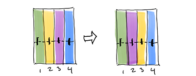
My final project is Guitar Hero for lacemaking. Bobbin lacemaking is a technique in textiles in which strands are braided together and managed on small spools called bobbins. Four strands are activated at a time and a manuever consists of crossing and twisting bobbins over and under one another. In the cross manuever, the bobbin in position (2) is moved over the bobbin to its right. In twist, the bobbins in position (2) and (4) move over each bobbin to their immediate left.
I wanted to align each week to the production of a final project as is best practice, but as I built skills and familiarity with subjects, the scope and flavor of the project changed. Below are the first passes.
final project | v1

crate digging as search
My research centers on optimizing labor resources in a design process. As such, I look for ways to navigate large design spaces. Looking through vinyls, for example, is an analagous process in which many factors contribute to a form of human-centered optimization: finding that perfect album.
This project will search a digital music library by haptic means, bringing the complexity and satisfaction of record-store crate digging home.
final project | v2
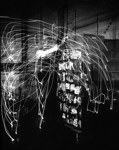
Frank and Lillian Gilbreth
An initial consideration is to make a machine to track motion. Somewhere between the pioneering time and motion studies of Frank and Lillian Gilbreth and the Strandbeests of Theo Jansen, I am interested in recording, controlling, and optimizing complex movements in machines.
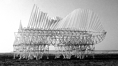
Theo Jansen Jansen's Linkage animated in Fusion 360
final project | v3
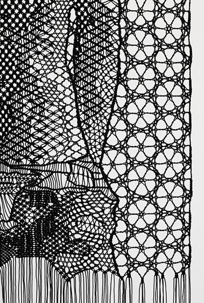
bobbin lace
I would like to create four bobbins that can sense their ordered position and register if they have performed a crossing or twisting manuever.
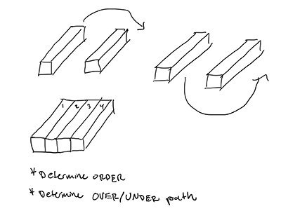
register order and manuevers
bobbinhero | production
After I committed fully to the concept of Guitar Hero for bobbin lacemaking, I focused my efforts on planning and production.
I tried to use each week effectively, but few individual weeks contributed directly to my final project, other than the useful information of what not to do.
inputs
In input devices week, I used the all-powerful step response behavior to sense whether a conductive bar placed in an electric field was being touched. As I learned more about this input, it seemed that it could be too difficult to implement this strategy to detect a change of dialectric properties in individual bobbins, as I had hoped to accomplish with this approach.
I tried another method of bobbin identification during networking & communications week, this time intending to give each a unique pulse-width modulated (PWM) infrared light signal. Again, a singular instance of the input was successful, but as I looked ahead to system integration, it seemed that it was going to be prohibitively difficult to separate the signals to detect which bobbin was where.
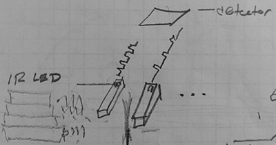
pewh pewh pew!
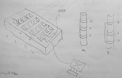
After a productive session with Zach, I decided on a system of conductive pads on which bobbins rest and, according to a unique and conductive pattern on each, ground high signals set through the internal pull-up resistors on the MCU. This way, each slot for the bobbins would know which bobbin is there. The strategy had to forgo the quite-important-to-lacemaking information of whether a bobbin traveled over versus under another bobbin, but I felt that the compromise was acceptable in the interest of finishing a final project.
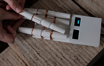
I designed the bobbins and the tray in Rhinocerous, and I knew from output devices week that I wanted to use the small OLED panels, so I fenestrated the housing for that purpose.
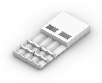
As my electronics were not finished, I had to estimate room in the "forehead" of my slightly-anthropomorphic design to house them. I also made the grounding pads at the end of the tray thin so that the bobbins would could only register in one orientation.
may the lace be with you
While I designed the tray and bobbins, I knew that I would 3D print the former and mold & cast the latter. I therefore kept machine tolerances and performance in mind so that, for example, the thin grounding geometries on the bobbins could be milled with a 1/8" flat mill. The OLEDs would be recessed minimally from the tray surface based on how thin the Sindoh could print with accuracy.
Casting was the preferred means of bobbin production (as opposed to 3D printing) because their geometry was shared and I wanted to test a variety of materials. Ultimately, the effort in molding & casting would pay off at scale and in material quality.
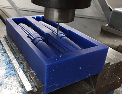
As in molding and casting week, I needed wax and a person that could use MasterCAM to produce my mold. I found both; Zain helped me get the .3DM into G-code.
We had some difficulty generating the toolpath for the thin grounding groove on the bobbin. I designed it at 1/8" to be end-milled by a bit of that type and size. On a flat surface, the results are as intended, as in the grooves connecting the signal rings on the bobbins. However, as the bit traces the semicircular arc of the groove, it cannot mill out all of the material at the end. We made a custom tool path that was wider at the base so that the top would be tangetial to the bit but it would not eat into material along its way to the bottom as it would have if we followed an extracted curve from the cylindrical geometry of the groove.
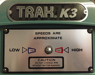
groovyI used the TRAK K3 milling machine, which is beautiful and enjoyable to use. Again, Zain helped me get set up.
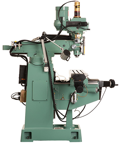
I particularly liked the speed dials at the top of the machine and the knobs that allowed a manual control over the velocity of the feed movement, but I digress.
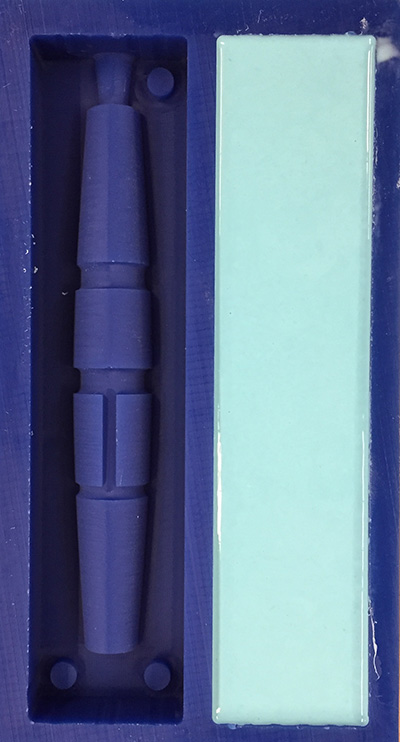
After the mold was milled, I used the tasty-looking but please-don't-eat two-part silicone Oomoo compound to create the negative rubber mold for the bobbins.
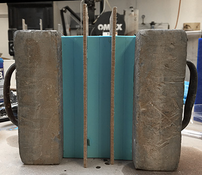
I reused the same mold design, including registration markers, as I had during molding and casting week, which saved some modelling time. I also wanted to save time by adding the exterior walls into the design instead of furnishing my own after milling. This made my overall mold shape larger than the standard 6" x 3" block we had been given during that week, but Jen provided me with an oversized one that I cut down to the size I needed.
now you see me, now you don't
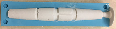
I mixed the compound and poured it into the mold in a thin pour from a high, steady location. This way, the silicone creeps outward and covers the mold with fewer bubbles. The results are always remarkable.
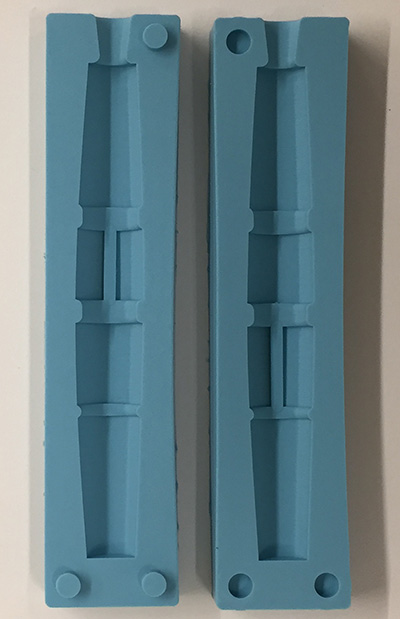
negative molds with positive results
I wanted to try casting the bobbins out of rubber, so I visited Reynolds Advanced Materials in Brighton to see the selection.
Before reading further, contact your shop manager about any two-part compounds you plan to use.
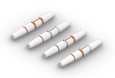
I used PMC-746, a polyurethane rubber compound that was relatively stiff but had some translucency. I dyed it with a very small drop of black So-Strong color tint.
With a cure time of 16 hours, I tried adding Kick-iT accelerator, but the pot-life was shortened so significantly that I could not cast the bobbins successfully because the mixture blocked the hole to pour into.
clogged pours
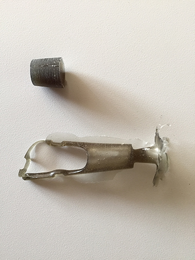
For the next attempt, I removed the accelerator. I filled the mold quickly and easily this time, and I came back the next day to a succesful cast. The orientation I chose for casting allows small bubbles to accumulate at the grooves, which is a little irritating, but I could not afford to be distracted by minutia.
While the second attempt was curing, I had prepared more OOm-molds to increase the volume capacity of production. With three molds, I was hopeful that I could finish the bobbins in this round. However, this cast yielded one succesful bobbin, as the hole became blocked during pouring again. I was not sure if I had filled the mold or not, but after demolding, it was apparent that I had not.
I was trying to be conservative with the rubber mixture because Alex and I were sharing this resource and she had to use a lot for her lamp. I therefore made a third attempt with two molds, feeling confident that I could pour and fill them. That part was succesful, but on demolding on yet another day, the compound had somehow not cured entirely and was sticky to the touch. Now the panic started to creep in and I decided to switch to Hydro-Stone, which had been reliable before.
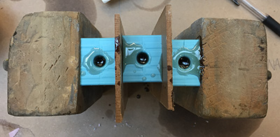
I cast the Hydro-Stone using all three negative molds. I should have made another mold, but I was not too concerned about this process and its short cure time, on the order of an hour rather than nearly a day.
The gypsum cement bobbins came out nicely, and I cast another two for a bit of redundancy.
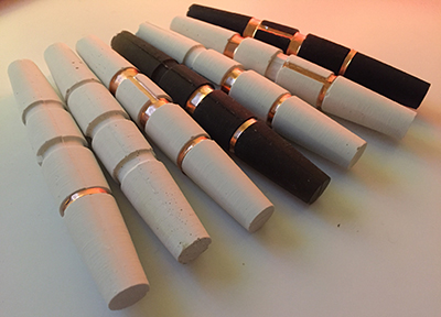
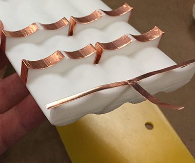
For the final preparation of the bobbins, I used the vinyl cutter to cut the copper roll into the continuous grooves. I used the exact geometry of the grooves to give me the pattern, but as with everything, there should be some tolerance because the copper came up a bit short when wrapping.
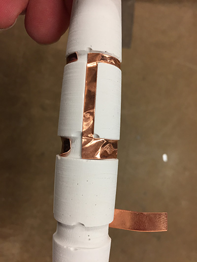
I recut and rewrapped the bobbins with copper.
output
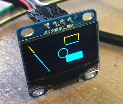
seeing doubleI started communicating with the (adorable) OLED panels during output devices week, and I wanted to use them for the displays of BobbinHero. One display could send the pattern maneuvers while the other could display a counter, for example.
Since that week, I had decided not to be a (bobbin) hero and work in the Arduino IDE instead of working with the raw C "Hello World" files that Neil provides. While Arduino is C, its libraries handle much of the obscure bit twiddling that are needed to communicate with the microchips. It is also well-documented online. I had resisted the temptation (I wasn't actually drawn to it, because I wanted to code the "right" way) until I had to use Arduino during wildcard week.
It can be difficult to find tolerable instruction videos not full of "uhhhs" or self-promotion, but I followed along with this video and quickly I could make customized content on the screens. Garage Geek Guy also posts useful links on his videos, including this one to a graphics library overview.
One piece of code worth replicating here for its generality is a means to determine what the address is of an I2C device:
#include <Wire.h>


void setup()
{
  Wire.begin();

  Serial.begin(9600);
  while (!Serial);
  Serial.println("\nI2C Scanner");
}


void loop()
{
  byte error, address;
  int nDevices;

  Serial.println("Scanning...");

  nDevices = 0;
  for(address = 1; address < 127; address++ )
  {
    // The i2c_scanner uses the return value of
    // the Write.endTransmisstion to see if
    // a device did acknowledge to the address.
    Wire.beginTransmission(address);
    error = Wire.endTransmission();

    if (error == 0)
    {
      Serial.print("I2C device found at address 0x");
      if (address<16)
        Serial.print("0");
      Serial.print(address,HEX);
      Serial.println("  !");

      nDevices++;
    }
    else if (error==4)
    {
      Serial.print("Unknow error at address 0x");
      if (address<16)
        Serial.print("0");
      Serial.println(address,HEX);
    }
  }
  if (nDevices == 0)
    Serial.println("No I2C devices found\n");
  else
    Serial.println("done\n");

  delay(5000);           // wait 5 seconds for next scan
}
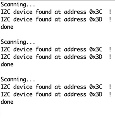
The SSD1306 OLED panel needs only four connections: GND, VCC, SDA, and SCL. When I connected a display and uploaded the I2C program, I found the address:
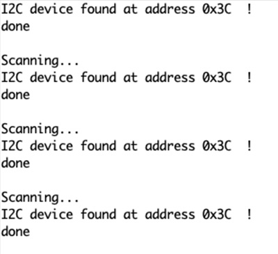
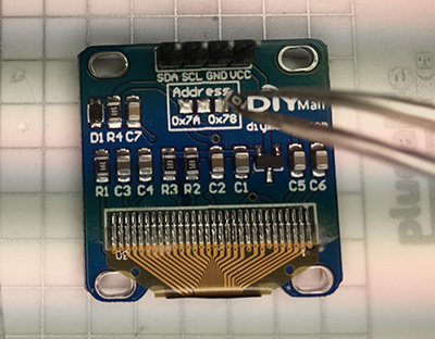
The panels also have a means to change the I2C address by switching the position of a 0 Ohm resistor on the back of the display; by default each panel was seen at 0x3C, but after changing the resistor position, it read at 0x3D. This way, I could communicate different messages to each display instead of simply operating in a mirror mode.
a healthy obsession?
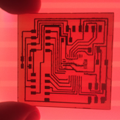
electronics design & production
I have enjoyed designing, milling, and populating boards this semester, which is fortunate since that process is repeated nearly every week. By the final project, I was good if not great at it, although I ran into several challenges.
My final Eagle files are provided here: .brd .sch
Because I needed 8 digital read pins for the inputs (perhaps I could have charliplexed and used fewer) and SDA and SCL for the OLEDs and wanted enough memory to handle the graphics and programming associated with BobbinHero, I selected the ATmega328P microcontroller from the Inventory. It's 32 Kb flash memory is positively gargantuan compared to the 4 Kb I had become accustomed to on other AVR RISC processors (see my glossery to parse the jargon). The only downside that I see is that its footprint make the once-seemingly-imcomprehensibly-small footprints of the ATtiny45, for example, seem positively gargantuan.
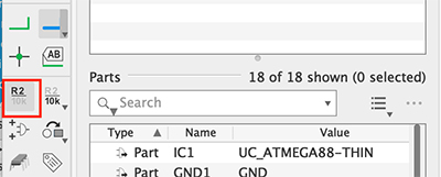
I brought in my components in the Schematic workspace of Eagle. I had recently discovered the ability to name individual traces and therefore create a kind of wireless schematic that is much easier to diagnose; since the schematic space bears little or no resemblence to the actual Board space, connecting the wires between components seems like clutter.
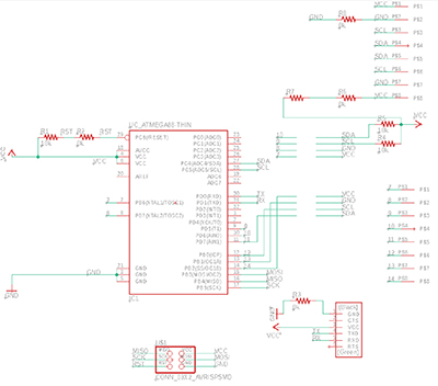
I also used this page from the Fab Academy as a resource because I had not designed a PCB for the ATmega328P before.
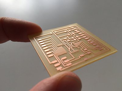
My first board layout went smoothly, or so I thought.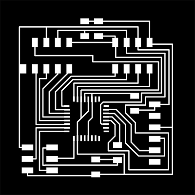
After I milled the board, I discovered that some of the traces had ripped up (they looked too thin) and some had fused together.
I thickened the traces and spaced them out further, believing that this would solve the problem.
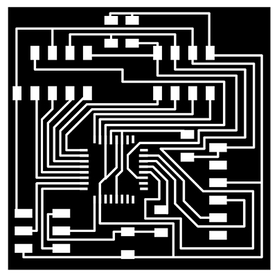
Again, several of the traces were fused together. I tried to separate the fused ones with a knife, but it had happened in enough locations that it was worth reworking the board. I also mistakenly ripped up traces while separating them.
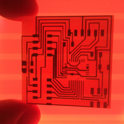
I also realized that the FTDI style connectors I like to use were conflicting with the "air rights" of the MCU. I therefore redesigned the board with thicker traces and a different layout. I also used this opportunity to think ahead to the integration phase in which the board would need to fit within the enclosure. Another realization was that the FTDI cable I was using for power and communication is stiff and wanted to come straight out of the enclosure, not turn and exit.
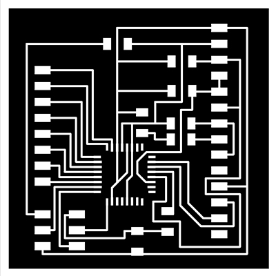
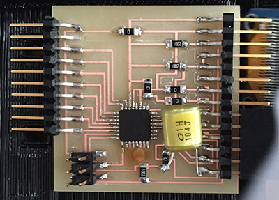
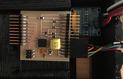
The third time was the charm, and I finally had a board I could work with.
Later, I added a capacitor between the RTS of the FTDI cable and the RESET pin on the MCU. This allowed the board to be programmed only with the FTDI cable instead of the typical ISP header. This was important because during programming, it turned out that I could not (easily) access the digital input state of the XTAL1 and XTAL2 pins that I had connected because of their convenient location. I switched those pins instead to the MISO / MOSI pins, and freeing them up this way was much advantageous. This may have been a problem with my board profile for the ATmega328P that I had loaded per the instructions on this HTMAA site.
embedded programming
Although I could conceptualize the logic for the Bobbin Hero program, it took many visits with Anthony to realize it. He is a true bobbin hero.
Each bobbin sits on three pads: one ground and two signal pads. The pads are connected to digital read pins on the microcontroller and their internal pull-up resistors are activated. If the bobbin does not pull the signal to ground (through its unique copper-groove signature), it stays high. There are (4) unique rows of pads (positions) and (4) unique bobbins. Each position needs to know what bobbin is there at a moment of reading.
The full program is found HERE.After some setup, each pad location (2 per bobbin for a total of 8) is defined at a pin.
#define Sense0_B  11 //(PB3) Sense Rows at (B)ottom or (T)op position
#define Sense0_T  12 //(PB4);
#define Sense1_B  5  //(PD5);
#define Sense1_T  6  //(PD6);
#define Sense2_B  7  //(PD7);
#define Sense2_T  8  //(PB0);
#define Sense3_B  9  //(PB1);
#define Sense3_T  10 //(PB2);
The pull-up resistors are activated at each location, giving each pin a default reading of HIGH.
pinMode(Sense0_B, INPUT_PULLUP);
pinMode(Sense0_T, INPUT_PULLUP);
pinMode(Sense1_B, INPUT_PULLUP);
pinMode(Sense1_T, INPUT_PULLUP);
pinMode(Sense2_B, INPUT_PULLUP);
pinMode(Sense2_T, INPUT_PULLUP);
pinMode(Sense3_B, INPUT_PULLUP);
pinMode(Sense3_T, INPUT_PULLUP);
The heart of the program is the readBobbins function, which takes the bobbin position as an argument and returns an integer corresponding to a unique bobbin.
int readBobbins(int location){
    int B=HIGH;
    int T=HIGH;
    if(location == 0){   // (4) if statements for where)
      B = digitalRead(Sense0_B);
      T = digitalRead(Sense0_T);
    }

    if(location == 1){
      B = digitalRead(Sense1_B);
      T = digitalRead(Sense1_T);
    }

    if(location == 2){
      B = digitalRead(Sense2_B);
      T = digitalRead(Sense2_T);
    }

    if(location == 3){
      B = digitalRead(Sense3_B);
      T = digitalRead(Sense3_T);
    }


    if(B == HIGH && T == HIGH){    //(4) if statements for what bobbin
      bobbin = 0;
    }
    if(B == LOW && T == HIGH){
      bobbin = 1;
    }
    if(B == HIGH && T == LOW){
      bobbin = 2;
    }
    if(B == LOW && T == LOW){
      bobbin = 3;
    }
  //  Serial.print("bobbin found    ");
  //  Serial.println(bobbin);
    return bobbin;
  }
The game begins with a reading of bobbins in each position.
current[0] = readBobbins(0);
Serial.print("current[0] =   ");
Serial.println(current[0]);
current[1] = readBobbins(1);
Serial.print("current[1] =  ");
Serial.println(current[1]);
current[2] = readBobbins(2);
Serial.print("current[2] =  ");
Serial.println(current[2]);
current[3] = readBobbins(3);
Serial.print("current[3] =  ");
Serial.println(current[3]);
A list of pattern types and their constituent manuevers (cross or twist) are read and displayed as instructions and corresponding goal position (these variables are defined earlier, but included here for narrative clarity).
int location = 0;
int bobbin =  0;

// 1 = Cross
// 0 = Twist
int patterns[1][3] = { //update values as added rows, columns
          {1, 0, 1}, //wholestitch
  //        {0, 1, 0, 1} //other stitch
  };
int numberPatterns = 1;
String patternNames[]={"wholestich", ""};

int last[]={0,1,2,3};
int goal[]={0,1,2,3};
int current[]={0,1,2,3};
int patternIndex=0;
int stitchIndex=0;
int movetype=0;

movetype=patterns[patternIndex][stitchIndex];


//then evaluate what goal should be in correct move
if (movetype == 0) { //TWIST
    goal[0] = last[1];
    goal[1] = last[0];
    goal[2] = last[3];
    goal[3] = last[2];
    display.print("TWIST      ");
    display.display();
}
else{
    goal[0] = last[0];//last[0]; //CROSS
    goal[1] = last[2];//last[2];
    goal[2] = last[1];//last[1];
    goal[3] = last[3];//last[3];
    display.print("CROSS      ");
    display.display();
}
//Serial.print("movetype =     ");
//  Serial.println(movetype);

Serial.print("goal [0] =     ");
  Serial.println(goal[0]);
Serial.print("goal [1] =     ");
  Serial.println(goal[1]);
Serial.print("goal [2] =     ");
  Serial.println(goal[2]);
Serial.print("goal [3] =     ");
  Serial.println(goal[3]);
After a 10 second countdown is displayed, the current positions of the bobbins are read again.
current[0] = readBobbins(0);
Serial.print("current[0] =   ");
Serial.println(current[0]);
current[1] = readBobbins(1);
Serial.print("current[1] =  ");
Serial.println(current[1]);
current[2] = readBobbins(2);
Serial.print("current[2] =  ");
Serial.println(current[2]);
current[3] = readBobbins(3);
Serial.print("current[3] =  ");
Serial.println(current[3]);
Finally, the current position is compared against the goal position and evalauted as succesful or not. If the manuever was succesful, the next manuever in the pattern is given; if the pattern is succesful, the next pattern (should be) given. Currently there is only one pattern, but there is room for more, as I am only using about 50% of the memory.
if ((current[0] == goal[0])
 && (current[1] == goal[1])
 && (current[2] == goal[2])
 && (current[3] == goal[3])){
  display.print("YES");
  Serial.println("YES");
  last[0] = goal[0];
  last[1] = goal[1];
  last[2] = goal[2];
  last[3] = goal[3];
  stitchIndex ++;

  if (stitchIndex >= sizeof(patterns[patternIndex])){

    Serial.println(patternNames[patternIndex]);
    stitchIndex = 0;
    patternIndex ++;

    if (patternIndex == numberPatterns){
      patternIndex=0;
      display.clearDisplay();
      display.print("wholestitch!");
      display.display();
    }
  }
}
else{Serial.println("FAIL");
  display.print("FAIL");
  last[0] = current[0];
  last[1] = current[1];
  last[2] = current[2];
  last[3] = current[3];
  stitchIndex=0;
}
My USBtinyISP that I fabricated during electronics production was starting to become a little tempermental, not always being recognized by Arduino, for example. I did not have time to troubleshoot a separate project, and I had had some difficulties programming during wildcard: advanced embedded programming so I decided to remove something I made from the loop and use the Atmel ICE programmer. With it, I was able to load code onto the board and read out serial data. Because my inputs and enclosure were not ready yet, I used a breadboard (desperate times et cetera) to simulate the bobbin positions changing. This worked well, but made the game exceedingly difficult. Nonetheless, the logic was in place and I could move towards integration.
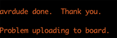
Or so I thought. The next morning, I borrowed a different Atmel ICE programmer and set out to tweak the game experience, in particular getting the second OLED to display graphics and instructions. I also intended to add more patterns to the bank of 1. However, as soon as I tried to upload a revision, I was met with alarming errors.
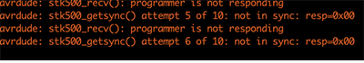
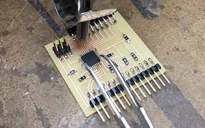
I tried the usual resets, shut downs, checking wires, recompiling, profanity, and so on but nothing worked. The only thing I suspected was that the previous night I had mistakenly pulled off the ISP header while a program was being uploaded. It did not seem to cause a problem then, but I was paranoid. I wanted to leave Anthony alone and solve this quickly. I had somehow mananged to solder those tiny little ATmega328P feet before, so I felt that replacing the chip had to solve the issue and that it was doable.
this is going to hurt me more that it will hurt you.
Probably the anxiety and frustration I was feeling diminished my soldering skills, and it took longer than I was hoping to get a new MCU on the board. I kept shorting those little legs together and had to get Lavender to help me remove a short that was causing me much consternation .
Finally, the new chip was on the board and I returned to my lair to program.
Now I'm getting the same messages and hours are lost. To say I was peeved would be to employ a bit of understatement.
I went to Anthony's office hours days and we began the diagnosis. We checked cables (he was suspicious of my short USB adapter running from the computer to the programmer because sometimes they only contain the charging pins and not the data ones). We were able to program from the Atmel ICE I had used before, so the chip was not bad, and probably never was. We determined that the particular Atmel ICE I had borrowed from Jen was faulty and would not program any boards. I have subsequently let Jen know about this issue, but it has not been fully investigated to date.
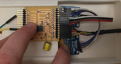
While frustrating, the experience was beneficial in that to circumvent the lack-of-a-programmer problem, Anthony added the capacitor between RTS of the FTDI cable and the RESEST pin on the MCU so that I could program through FTDI only. I could then remove the tall ISP header and replace it with the low-profile pins I favor and actually score a nice victory towards systems integration.
integration
Working in parallel is a bit frenetic, at least on one's own because you are in effect managing and producing several projects at once. Nonetheless, this was certainly best practice for this project as any one of the categories could have lasted until the end of time if pushed to their fullest expression or potential. It was good practice to get something working to some minimal threshold and just move on. I'm always amazed at how long (almost) everything takes. However, as everything started to come together, I finally got into a flow state.
I had 3D printed a new enclosure in black to match the black rubber bobbins, and included a recessed pocket for the electronics board, for which I now had the exact dimensions. When I tried to bring components together however, it was clear that the stiff jumper wires I used from the board to the OLEDs and the FTDI cable, which would have been slightly off-center, would still not be happy.
this one is too small
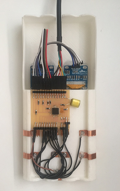
Instead I went back to my original 3D print, which I had abanded because I thought the profile was too slim. The removal of the ISP header allowed for the entire board to sit within a depth less than 1/4". The deeper "forehead" could be used in the future for batteries if I wanted to untether BobbinHero from the computer. In the meantime, it was far more accommodating of the wires than the smaller black design had been.
this one is just right
I applied the copper foil to the enclosure, using the rigid plastic scraper to push the foil down firmly and evenly onto the 3D print.
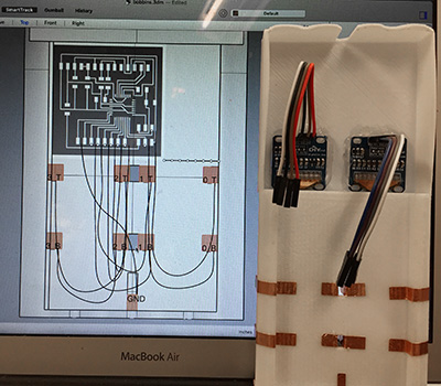
I hot glued the eyeballs OLEDs and PCB into to place and wired them together. Finally, I was ready to wire each of the foil pads, which wrapped onto the bottom surface of the enclosure to their corresponding pin traces. I used the 3D model in rhino and imported the PCB design as an image to help me plan the wire routing. Again, it was the stiffness of the wires that I was planning around, so I made the most generous curves possible for the wires to follow so that there was less stress on the ends.
I used hot glue to help protect the wire connections to the foil pads and heat shrink enclosures at the pin connector ends.
all systems go
summary
What does it do?
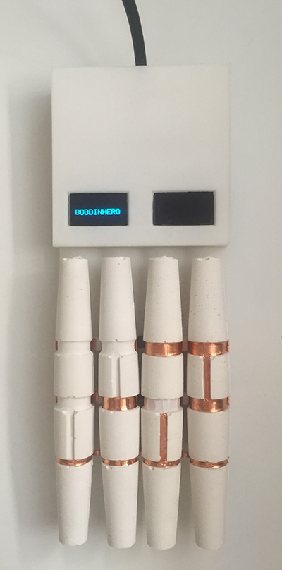
BobbinHero is a lacemaking simulator that displays instructions for bobbin lace patterns and tracks the motion of (4) unique bobbins to record whether the appropriate movement has been made.
Interactive video games with specialized controllers, e.g. Guitar Hero or Dance Dance Revolutionhave existed for decades. BobbinHero seems to be the first such game dedicated to bobbin lacemaking.
What did you design?
I designed the enclosure and form-factor, bobbins, electrical contacts & routing, electronics board, embedded programming, and graphics.
What parts and systems were made?
- bobbins
- enclosure
- electronics board
- program
- graphical interface
- bobbin detection system
What materials and components were used? Where did they come from? How much did they cost?
Materials
Hydro-Stone Gypsum Cement
Price: $15.95 / 15 lbs
Source: RPL
Application: bobbins
PMC-746 Polyurethane Rubber Compound
Price: $36 / 3 lbs
Source: Reynolds Advanced materials
Application: bobbins
So-Strong Color Tint (Black)
Price: $14.55 / 2oz
Source: Reynolds Advanced Materials
Application: rubber bobbins
Oomoo 25 Silicone Rubber Compound
Price: $27.25 / 2.8 labs
Source: RPL
Application:bobbin negative molds
Machinable Wax 1.5"x6"x12"
Price: $24.95
Source: RPL
Application: bobbin positive mold
3DWOX Refillable Cartridge PLA (White)
Price: $49.99
Source: RPL
Application: enclosure
3M #1126 Copper Tape w/ Conductive Adhesive
Price: $246.04 / 6" x 36 yds
Source: RPL
Application: electrical contact @ bobbins & enclosure
Single Sided Machinable PCB Stock
Price: $1.40 / 6" x 8"
Source: RPL
Application: electronics boards
MC10M-50-ND Flat Ribbon Cable
Price: $38.07 / 50'
Source: RPL
Application: wiring
Heat Shrink Tubing (1/16")
Price: $0.76 / 4 ft
Source: EDS
Application: wiring protection
Components
F/F Jumper Wires
Price: $3.95 / 40 pcs
Source: EDS
Quantity: (8)
Application: OLED connections
I2C Serial 128X64 OLED Display Module
Price: $8.99 / ea
Source: EDS / RPL
Quantity: (2)
Application: displays
ATMEGA328P-AU Microcontroller
Price: $1.84 ea @ 25
Source: RPL
Quantity: (1)
Application: microcontroller
311-10.0KFRCT-ND 10K OHM Resistor
Price: $6.37 / 1000
Source: RPL
Quantity: (3)
Application: electronics board
311-0.0ERCT-ND 0K OHM Resistor
Price: $4.77 / 1000
Source: RPL
Quantity: (5)
Application: electronics board
S1143E-36-ND Right Angle Header
Price: $3.78 @ 360
Source: RPL
Quantity: (28)
Application: electronics board
What processes were used?
Casting
- Hydro-Stone bobbins
- Polyurethane Rubber bobbins
- enclosure (final)
- enclosure (black edition prototype)
- PCB production (2-axis)
- bobbin positive mold (3-axis)
- copper tape for bobbins & pads
- PCB production
- bobbin detector production
- desoldering with heatgun & braided copper
- gluing
- sanding
- taping(temporary)
What questions were answered?
Can there really be a Guitar Hero for lacemaking? Will I ever be able to solder these tiny little feet to the board? Can I program a game that is surprisingly satisfying to play? Will it work at the final demonstration? Yes!
How was it evaluated?
BobbinHero is successful with room for improvement. The game that is loaded into the MCU works, although the electrical connection (which relies on direct contact at 3 locations for 4 bobbins) is unsurprisingly finicky. The rubber bobbins have an easier time of making contact due to their flexibility. At the final demonstration, Neil suggested employing alternating current using Step Response to read the locations instead of a direct current connection, and this is something I've been trying to work with since Input Devices week and for which I would like to find an application. More patterns need to be added to the bank and the second display needs to show graphics or instructions. I would like to work on this project more.
What are the implications?
While much of my commentary acknowledges the seemingly absurd nature of the concept, my research interest is in understanding the embodied effort of design and uses lacemaking as an example because of its limited ruleset paired with a complex design space. I hope to use BobbinHero to further understand the effort it takes to produce bobbin lace.
acknowledgements
Anthony Pennes deserves a special acknowledgment for his (bobbin) heroism in helping BobbinHero become a reality. The TA squad (Molly, Diego, Jung, Paloma, Zain) were all hugely helpul and the work could not have happened without them. Jen taught and put up with us all and I hope we've repaid her with a clean shop and returned tools. Every class contained at least one jaw-dropping feat by my colleagues across all sections and kept me motivated. Thank you, Neil, for creating a class that I routinely describe as "insane" and one of the most fun things I've done at a university - legally.