how to (almost) make (almost) anything
input devices
touch bar
I am using this week to get started on my final project in which I would like to create Guitar Hero for lacemaking. Bobbin lacemaking is a technique in textiles in which strands are braided together and managed on small spools called bobbins. Four strands are activated at a time and a manuever consists of crossing and twisting bobbins over and under one another respectively.
I would like to create four bobbins that can sense their ordered position and register if they have performed a crossing or twisting manuever.
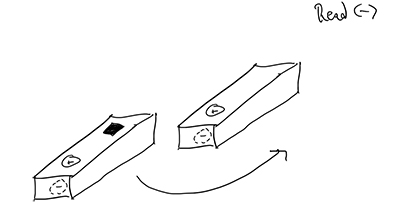
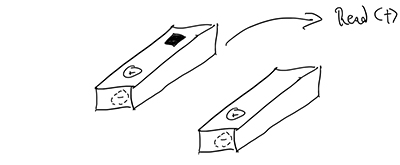
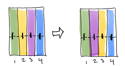 reorder
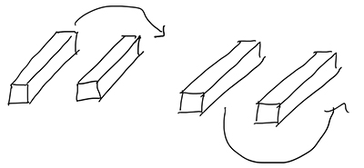 "cross" and "twist"
first instinct: Hall-effect
An initial approach to registering the cross and twist manuevers is to place a both a Hall-effect sensor and a coin battery in each bobbin. When the sensor passes under a bobbin, it would be in the negative magnetic field of the battery and when it passes over a bobbin, it would be in the positive magnetic field.
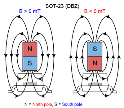 hall-effect sensor in a magnetic field
 twisting and crossing
After talking to Anthony and Alexandre, it was clear that wirelessly networked bobbins would be exceptionally complicated and that there could be more effective strategies. One such strategy was to simply have a tray for the bobbins, each of which could have a different internal resistance and would complete a circuit in its slot in the tray. When a bobbin was pulled out, it would be registered through logic that it was moving. I liked the simplicity, but I was not sure that this approach would qualify in the spirit of input devices week.
second attempt: step response
I was drawn to Neil's introduction of the "incredibly simple, incredibly powerful" step response behavior and particularly its application to dielectric spectroscopy. I revised my approach to place bobbins of differing materials (or perhaps one material but with excavated pockets) in an electric field and measure the reponse as the capacitance of the objects changed. I set out to reproduce the transmit-recieve example.
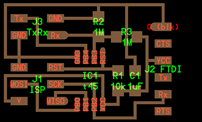
fabricating the board
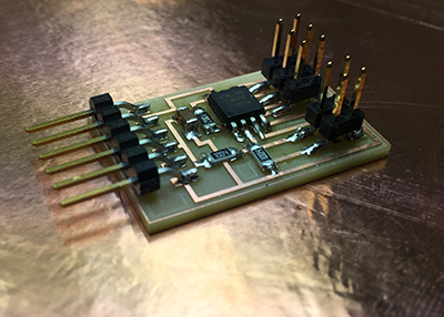
By now, producing a printed circuit board (PCB) is all but routine. I followed the same procedures as week 3 and week 5, using Neil's hello.txrx.45 board design and associated PNG files for the traces and outline.
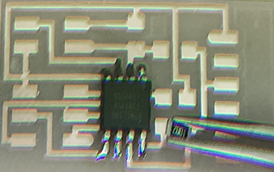
I made quick work of soldering the components onto the board, always placing a small amount of solder onto a pad and then bringing the part to the solder while reheating. Once the component is stuck in position, it is not hard to go around the rest of the connection points.
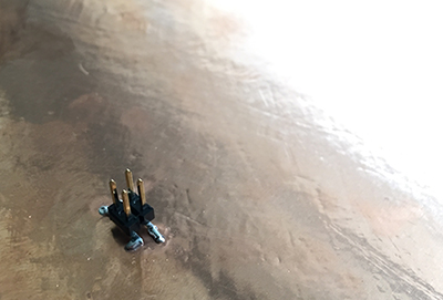
 nobody move
Within minutes, the board was populated (I have word aversion for "stuffing") with components and ready to send down the assembly line - to myself.
fabricating the plates
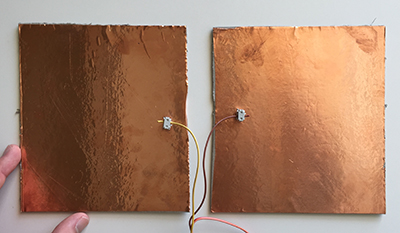
I needed to connect the transmission and receiving pins each to a sheet of conducting metal so that there would be an electric field between them. I used the copper roll with an adhesive backing (usally used for the vinyl cutter) and cut two square pieces measuring about 5.5" on each side off. I used the contact paper transfer technique from week 2 and attached the copper sheets to a thick chipboard for a backing. Finally, I soldered a 2x2 pin header connection to each pad to receive the transmission or receiving pins from the board. I soldered all of the feet to the copper so that orientation does not matter as only one wire was connected back to the board for each bad.
Despite the abundance of room to work, soldering the feet of the connector pin was more difficult than soldering the board. This is because the copper sheets disperse the heat from the iron quickly and it is hard to get the solder to flow onto the sheet.
programming the board
I still had not fully understood Make and AVRDUDE, but I wanted more experience programming the boards from this environment to supplement the Arduino developer environment I had used before. I downloaded the .make and .c files for the transmit-receive step response example and found Alexandre's very useful and high-level tutorial on Make.
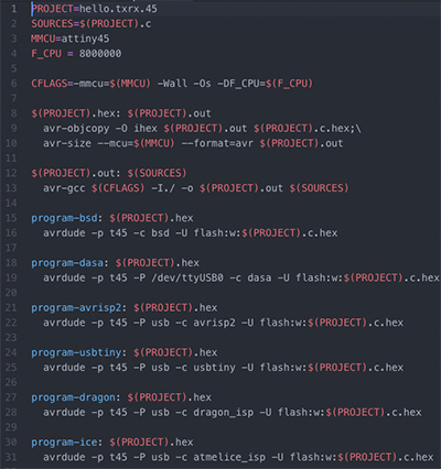
I connected the USBTiny programmer to the computer and the board to the USBTiny. The FTDI cable was also connected to the board and to another USB port. I ran the command:make -f hello.txrx.45.c.make program-usbtiny
This time, I understood from the tutorial that the specific information necessary to program is nested within the .make file. That is, Make runs a file (-f filename) and programs a microcontroller (-p t45) through a port (-P usb) it with the programmer configuration (-c usbtiny) and performs a memory option (-U flash, e.g.). What it puts onto the controller is the .hex file that it compiles with avr-gcc. The terms from my running glossery are starting to come together. It also made sense why these inputs are specified from the graphical interface of the Arduino environment. Inspecting the .make file in an editor, it is clear how other programmers are included and could be used if they were available.
 .makes sense
running the program
With no LED on the board, there was no immediate way of knowing if the programming had been succesful. In retrospect, this would be a very good idea to include one. The next step was to run a Python script provided with the example, and so I used the command:
python3 hello.txrx.45.py
I was greeeted rather quickly with the following admonition:
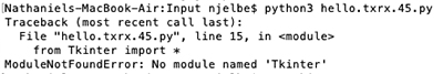
I could not pronounce, and I did not know, what "Tkinter" was, so I searched online and found that it is "Python's de-facto standard GUI package". I tried installing the package with pip install tkinter and brew install tkinter but was having no success.
I found a number of tutorials online, and I was eventually able to install tkinter.
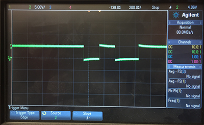
Meanwhile, I had moved to the Engineering Design Studio (EDS) to consult with Anthony. We set up the board to program from the lab Linux machine, but we were unable to verify if the program had installed. We took the setup to an oscilliscope and were able to confirm that there was activity.
After running the Python script again, I was missing another module, and at this point I reached out to Diego.
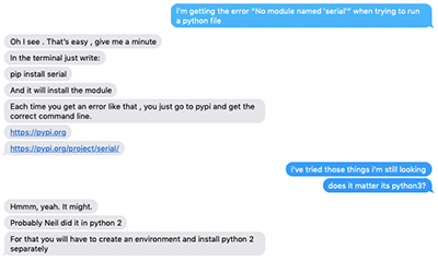 We determined that one problem could be that I was using Python3 and Neil probably used Python2 when the example file was created. Diego pointed me towards some tutorials for creating a Python environment that can run older versions. I also installed pip and serial.