how to (almost) make (almost) anything
computer-controlled machining
 something old, something new
This week was heavily anticipated with tales of coffee tables and bookshelves aplenty. However, I am not particularly drawn to the common CNC aesthetic of slots and tabs and wanted to think different. I thoroughly enjoyed the example of a large programmer and considered remaking the Jansen linkage again, but I have already made it out of cardboard and 3D printed it, and I needed a change. I also looked into mechanical digital to analogue converters, but ultimately decided against moving parts with Chris Dewart's concise summary of the material properties of oriented strand board: "it's like an oatmeal cookie."
My partner and I cohabitate and, as Alex is also enrolled in this class, decided to collaborate on a pair of side tables. We were drawn to the examples of Japanese joinery given by Neil in class and decided to make big Japanese joints that were reconfigurable and could serve as small tables.
We each designed a joint, comparing critical dimensions. My workflow involved a Grasshopper definition that parametricized a dovetail joint with an additional alignment slot. The dovetail could change shape and location within the block while the overall height would stay at 18".
slot machineOur initial ambitions had been to each make a pair of tables that could also double as stools. Once we contoured the models and started to lay them out on a sheet, we found that we would each require more than one sheet of OSB and began to narrow the scope and ambition of the project.
We also needed a strategy for lightening the tables, as any design that uses nearly the entire sheet of material would be very heavy, despite its compact size. We adjusted the proportions to allow for the top part of the joint to be milled from within the area of the bottom part. In this way, we lightened the block and saved valuable nesting space on the sheet of material. A final nested layer removed yet more material from the top block.
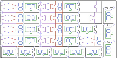 investing in nesting
The outlines were brought into MasterCAM in order to generate toolpaths for the Onsrud CNC machine. Zain helped set up this process, and to expedite the matter he used speeds and feeds from a previous student. Nevertheless, each layer, called levels in MasterCAM, had to be worked through to add all the geometry and ensure that the tool was cutting on the correct side of the line. We were climb milling and therfore the geometry was always to the left of the tool. I also had to ensure that I was removing material on the correct side of the line and therefore closed geometry would be milled either clockwise or counter-clockwise.
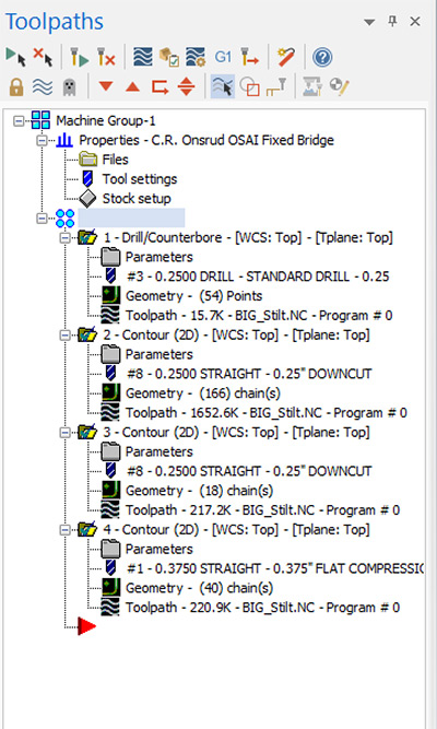
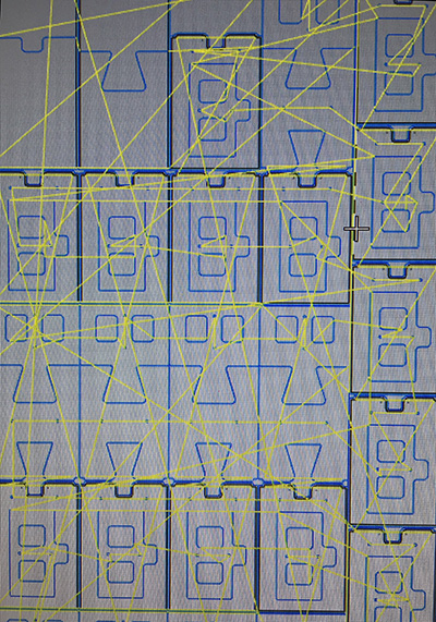 toolpaths
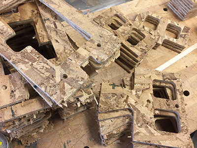
With the G-code exported from MasterCAM and loaded onto the Onsrud console, we loaded a 4x8 sheet of OSB and secured it with two vaccuum pumps and perimeter tape. Additional fixturing included the depth of the cuts to allow an onion skin so that pieces would not get loose. At times, however, small pieces got loose and out of plane and so I paused the machine before clearing the debris with a long stick.
Who but C.R. Onsrud?One mistake that was carried over from using another student's file as a template for the toolpaths was that a substitution had to be made during the milling process. Zain stopped the machine and reloaded the rest of the routine; the error was that returning to the #1 library tool at 3/8" would have prohibited the correct details designed at 1/4" resolution from being milled.
After the job was finished, I vaccuumed the bed being mindful not to pull up some of the smaller pieces. I popped out the rest of the pieces and sanded them to remove the onion skins used for fixturing.
 hors d'oeuvres?
We set up a simple jig with clamps and scrap wood in the shop and began gluing and laminating the pieces. As we got better at this process, we used a quick release clamp to hold the work between each successive layering.
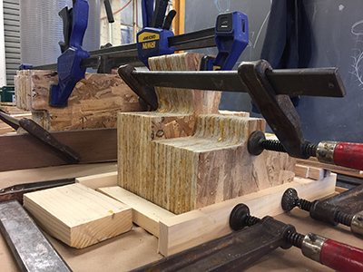 laminating process
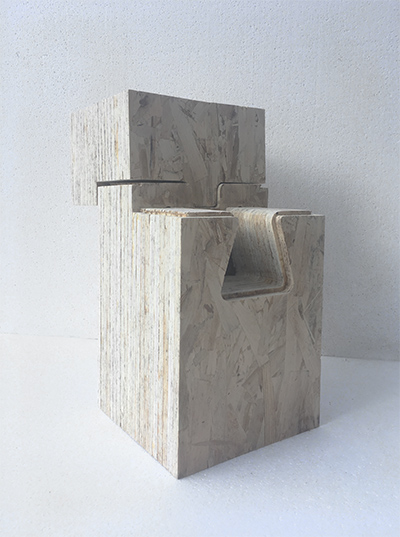
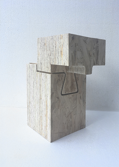
One of the fussier considerations was the design of a 1/4" reveal that was to be determined by the bit used for the milling. The end laminations are therefore milled from a single rectangle with the reveal determined by the bit. In turn, the line that the mill followed on the end faces was offset 1/4" to create the contours for the interior pieces. The idea was that the top part of the table would sit directly on this offset line in order to maintain the 1/4" reveal on the end faces and hold the joint in place. We did not provide clearance, however, and this required a lot of sanding and cajoling to get the joint to operate.
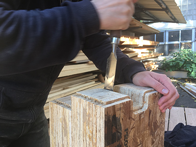 inner layers were designed for a perfect fit
All middle laminations include two notches that were milled separately to align with the reveal on the end laminations. Fortunately, this worked and the reveal looks as intended.
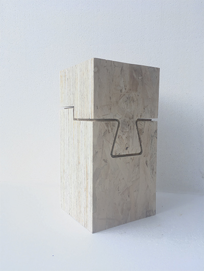 revealing an artifact of the CNC process
Once the notches worked, we continued to sand the surfaces of the piece until the OSB became smooth; after enough sanding, the OSB takes on an almost marbled appearance.