how to (almost) make (almost) anything
output devices
 oh, hello.
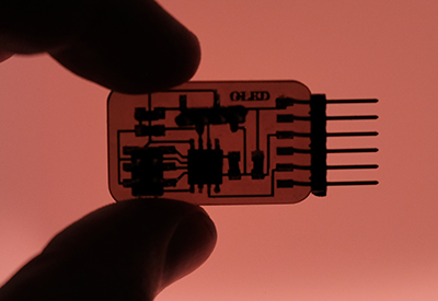
This week I wanted to try one of the newer items in the inventory, a small OLED panel. I am intereted in a display that can address each pixel individually and that is also generally useful for debugging.
board design
I based my board off of Neil's example, but I redesigned it. I wanted to switch the processor to a larger ATTiny85, which has 8Kb of flash memory instead of the 4Kb on the ATTiny45, but I did not see any on the inventory or in the shop. I also thought there was a free PIN in the design, to which I would have liked to attach a status LED, but I realized I had misread the diagram and that there was no free PIN for the ATTiny45. Nevertheless, I redesigned the layout to my liking and it was another chance to practice the art of production.
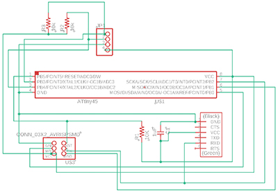
I followed the procedures from week 5 and started by making sure I brought in the correct libraries and design rules from the Control Panel in Eagle. In the Schematic window, I used the command add to bring in the components necessary. My design called for one offset pin connector that was not in the standard eagle_fab library, but I was able to find a supplemental library online and bring it in.
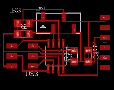
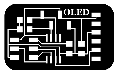
I exported the completed board design as a PNG, but the process is still not painless. I could not get the file to recognize the yellow window bounding box that seems like it should act as a viewport. Instead, traces of the viewport are in the PNG file, and so I have to post-process the PNG in Photoshop. I also add some text, fillets, and the outline cut from Photoshop. I would like to automate much of this process, and I found a Python script that could help on the class site, but I did not have success and will have to retry at a later point.

board production
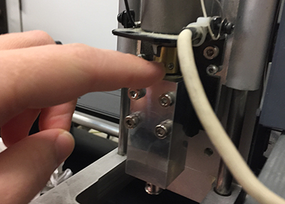
While much of the board production is becoming routine, there are occasional difficulties. The Roland MDX-20, the older mill which I like to use, cut only a shallow engraving on the copper instead of turning up the beige debris that indicates a good cut. On closer inspection, the shaft that holds the tool had some movement in the z-axis, so even after setting zero by pressing the bit into the copper, it would not stay in the material. I alerted Jen to the problem and we took the machine apart and tightened a set screw that must have come loose. My theory was that somebody may have inadvertently loosened the wrong set screw, but Jen was more generous.
I also had difficulties loading my PNG, the most obvious of which was that the size seemed off by a factor of two. More frustrating, the file would not finish calculating in MODS. On one occasion, I could preview the paths in the seperate window that opens, and it seemed like there may have been a problem with the paths near my initials that I had placed close to the edge. I revised the PNG to remove the initials.
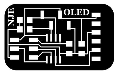 initials too close to edge
While I had the file open, I noticed that the size was wrong; it was about (probably exactly) twice as big as it should have been. I went back to Eagle and exported the board again and post-processed the PNG in Photoshop.
Finally, the mill was working and my file would calculate as expected in MODS, but there was one more gaffe. When I milled the cutting outline, the resolution was set incorrectly, to 72 instead of 1000, in MODS and therefore the arc that the machine began cutting was massive. It was so large that my correctly sized piece fit in the corner between the arc of the bottom left fillet and the origin. It was by luck that the cut did not go straight through my board. I stopped the machine, changed the resolution, recalculated, and finally milled the cut outline. Relieved, I removed the board, washed it, and prepared for soldering.
Soldring was uneventful except for the fact that I was at a different station than I am usually, and the tool felt different. I could not seem to get the heat of the solder gun where I like it. Finally, the board was complete.
testing OLED panel
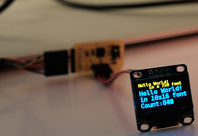
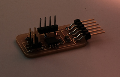
I attached the OLED to the board with four individual connector wires; I will probably reuse the display and I did not want to resolder between boards.
I connected the USBTiny programmer to my board and to a USB port on my computer. I attached the FTDI cable from another USB port to the board. With anticipation, I ran the following command:
make -f hello.SSD1306.make program-usbtiny
I was prepared for errors, but unprepared for the result:
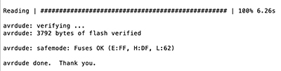 you're welcome
changing the file
With the display operational, I will now set about customizing the display text. I would like it to display a series of custom characters, with the eventual goal that these characters will be decided through an input routine.