how to (almost) make (almost) anything
networking & communications
This week I pursued a way to ensure that the bobbins of my Guitar Hero-for-lacemaking project will have communication with a set of sensors that will register in which position they are. This information will be used to decide what types of lace are being made through the user movements. I think.
strategize
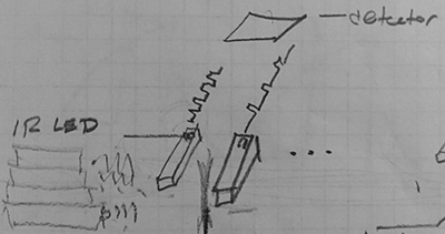
During input devices week, I used the step response behavior to sense a change in capacitance between two plates. This was interesting, and I was drawn to the relative simplicity of the set up, but I have decided (through a lot of consulatation: thank you Rob Hart of Harvard and Zach of MIT) that parsing the signals between the different bobbins would likely be troublesome. I needed a different strategy, and so having talked about infrared with Rob, Zach, and former How To Maker Julia, I decided to send a unique infrared pulse from each of the four bobbins to a set of infrared sensors. More of this though process is is on the final tracking page.
generate PWM
Pulse-width modulation is at the core of HTM(A)A, and this seemed like a good application. I needed each bobbin to produce different signals so that their unique identity could be registered at a sensor. To simplify the sensing procedure, it seemed like a good idea that each bobbin would send a pulse at the same frequency, but of differing duty cycles.
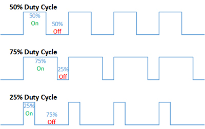
The relative on-ness and off-ness of the IR LED, at the same frequency, separates the signals.
The microcontrollers we have been using can generate PWM, but it seemed overly complicated and uneccessary to instrument each bobbin. Instead, Anthony directed me towards a 555 timer integrated circuit, which can generate square waves. Getting PWM from it, however, was not rife with instant gratification.
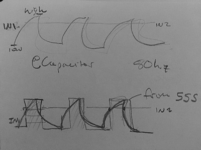
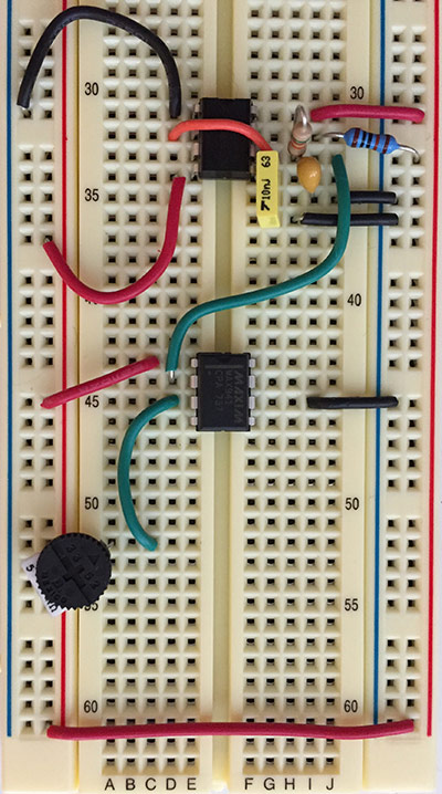
At this point, I have to thank Hannah for a deus ex machina for the ages. Hannah overheard Anthony and me talking and recognized the problem - she had worked on it before. We started putting together a schematic on a breadboard (sorry Neil) and drew diagrams and referenced datasheets. The idea was to get a charge-discharge curve from a capacitor attached to the 555 and run it through a comparator with a voltage level that fell within the amplitude of the curve. When the comparator saw the curve was higher than the voltage, it output a logic level of 1; when the curve was less than voltage, it output a logic level of 0. In this way, changing the resistors on a simple voltage divider could move the input to the comparator and intersect the charge-discharge curve differently, generating different duty cycles for pulse-width modulation.
Another consideration was that we needed a relatively low frequency for the signal so that the microprocessor on the sensing end could resolve it. Using
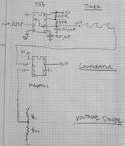
f = 1.44/(Ra+2Rb)C
we were able to select resistors for the 555 at 100k and 49k and a capicitor at 0.1uF and calculate a frequency of 72hz, on the order that Anthony had suggested.
 schematic and mockup
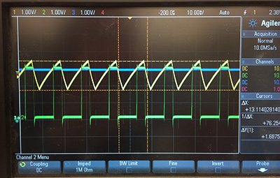
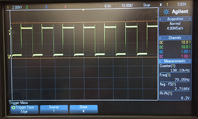
After many hours, we were able to generate PWM. In the images below, the yellow channel is the charge-discharge curve from the 555 timer and the IN+ signal into the comparator; the blue is the voltage after a voltage divider and the IN- signal into the comparator. The green channel is the PWM signal.
On the breadboard, we used a potentiometer (variable resistor) so that we could increase and decrease the value of the voltage from the divider and therefore create different PWM signals.
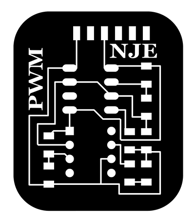
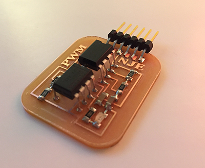
PWM board production
Confirming that the design worked, I designed a PCB to generate PWM from a 555 timer and comparator. I began with a schematic in Eagle, as usual. It helped to draw out the schematic (above) beforehand, especially since this board had no precedence (such as Neil's examples for the class). I did have to track down the components that were not in the library: the MAX941 comparator and NE555 timer.
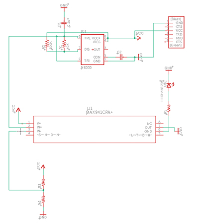
In the Board workspace in Eagle, I could not figure out how to through-mount the components that were designed for the breadboard, so I used surface mounted pads and resiged to those components being on stilts; I would like to resolve this workflow in the future. I also used an FTDI connector, when I only need Vcc and GND pins, but powering the board with the FTDI is easy. The next step is to connect batteries, as the bobbins will be untethered.
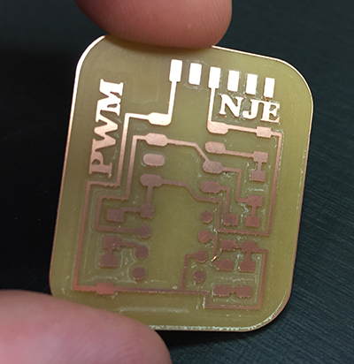
Milling was uneventful this week, as I had re-learned several lessons last week. However, I did overreach to create a generic ATTiny45 board, which can be seen in the final project tracker.
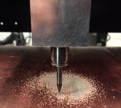
 mill-IR time
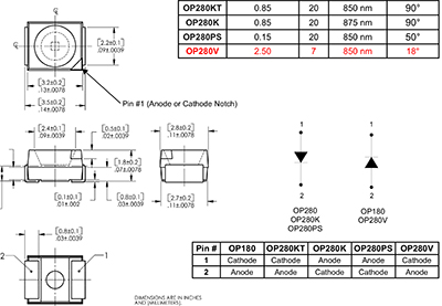
Finally, I populated the board with the components. I had to track down the datasheet for the IR LED since it was marked with a notch and I was not sure which side was anode or cathode. The model was supposedly the OP280KT, on which the notch should point towards ground. Spoiler alert: this turned out to be wrong later.
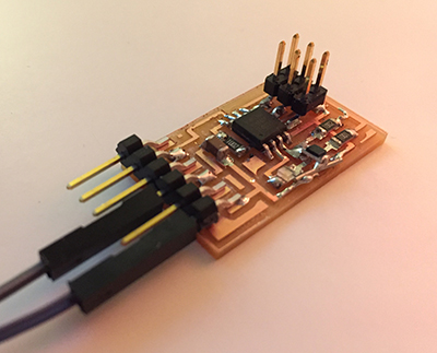
synchronous detection board production
With a board to produce an IR LED signal, I needed a board to receive the signal. This was also appropriate and necessary for Networking week. I designed a board with two IR phototransistors and two status LEDs, the idea being that if I created two PWM boards, I could point them at the sensor board and when the IR sensor saw its appropriate IR signal, the LED would light up. The final project tracking page will finish that story, but in the meantime, I simply used Neil's synchronous detection board and replaced the IR LED with a blue LED so that it could illuminate when the IR phototransistor recieved the IR LED signal.
testing
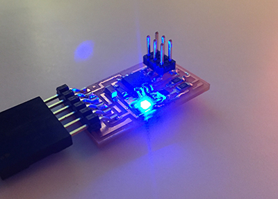
The PWM board does not have a microcontroller on it, so there is no programming for it. For the IR phototransistor board, I loaded it with the synchronous detection program from Neil's examples. The board accepted the program with no problems, and the blue LED lit up, presumably in the pattern than Neil's IR would light up. It is always reassuring to see an LED light up.
On the oscilliscope, I confirmed that I got PWM signal at the output of the PWM board. I attached power and ground to the inputs and probed where the signal should be sent with the scope. Happily, I saw the signal I was anticipating.
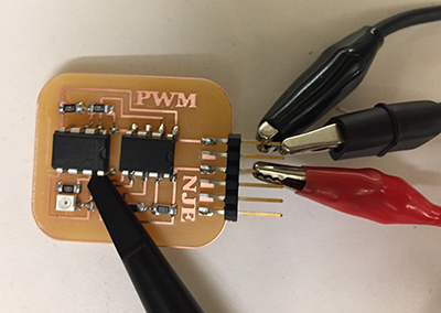 alligator attack
Testing was not complete, however, because I had still not shown that the IR signal was 1.) generated or 2.) received. When I had attached the phototransistor, the datasheet said that the cathode side was at the collector, which was at the pin according to the example. It did not make sense why the cathode would be on the high side of the transistor, but I know that transistors are strange, so I placed it so that the collector was where it should be. When I powered both boards and aimed the IR LED to the IR phototransistor and probed, I got no signal. I first thought to de-solder the phototransistor, so I did. Brutally. I ended up ripping up some trace and simply destroying the phototransistor in the process. Anthony, who should probably be a surgeon, helped me patch up the rail and put another phototransistor on. After discussion, we had decided to leave the cathode side at the collector.
I still got no signal, and so we took a look at the IR LED on the PWM board. The LED had signal right before it, but was drawing no current across it. It must have been backwards, despite the datasheet. I quickly replaced the LED with a different model (the OP280KT was discontinued anyway) and made sure the cathode was towards ground. I powered everything on and was able to see the PWM signal on the IR phototransistor board. The signal was proportional to distance between the LED and phototransistor and their angle towards each other. Mission accomplished!
IR FTW