Final Project
Smart Sensing Staircase
Brainstorming and Initial Ideas
Some initial ideas that I had were:
- Automated Tattoo Machine
- Pipe organ that plays itself based on ambient sound
- Self opening/set upping mosquito tent
- Sewing machine that can embroider patterns based on images passed in
- Snake/reptile tank where the user can regulate the temperature and humidity
After some thought and talking through these ideas with staff, I decided to go with making a tank where the user can regulate the temperature and humidity. In order to regulate temperature I needed to buy a DC heating pad (to be easier to override) as well as sensors that could measure the temperature and humidity. I ordered the following materials:
Unfortunately when the heating pad arrived, I tried to pass current through it and it didn't work. The heating pad was central to the project and I couldn't afford to wait 2 days until a replacement arrived and making a heating pad didn't seem especially feasible. I sat down with staff to try to figure out alternatives I could complete.
Redefining the Project
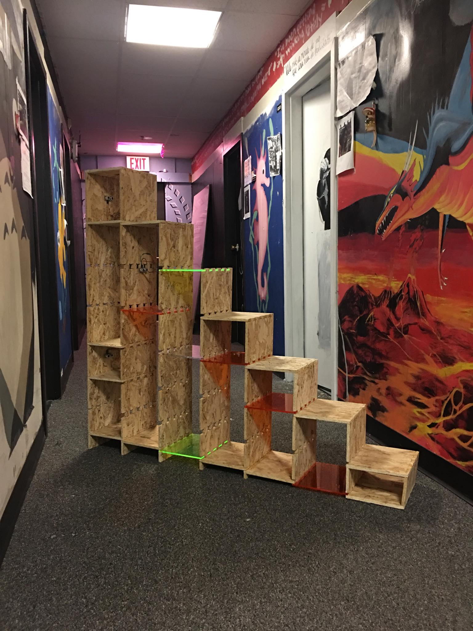
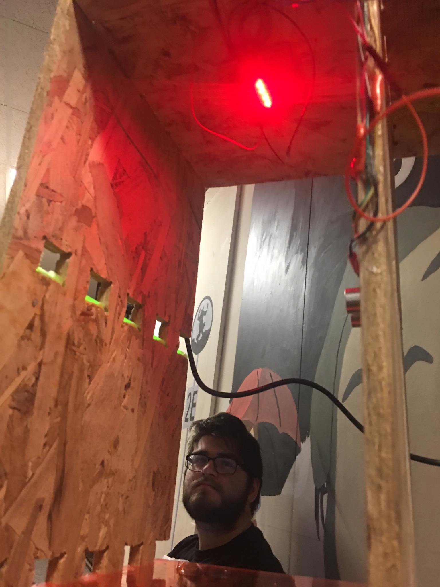
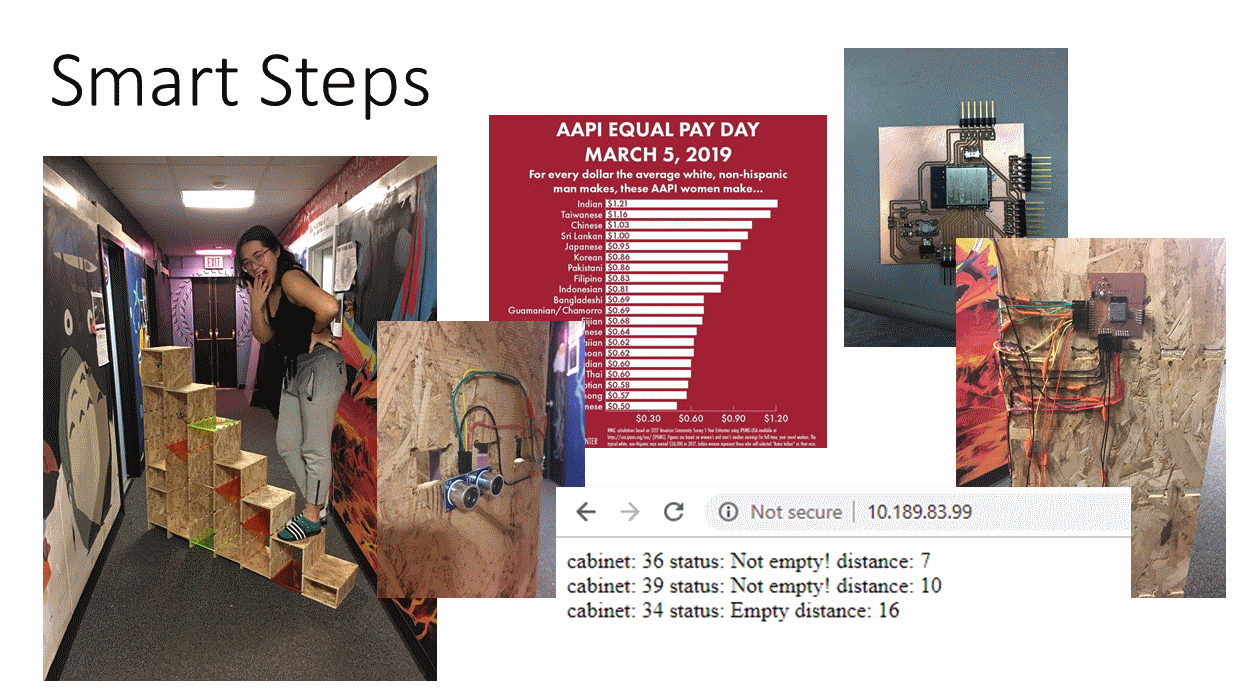
After speaking with the lab instructor, we redefined my project to make use of what I had already implemented for the class. From then my final project evolved into a Smart Sensing Staircase. The staircase would have many compartments and within them there would ultrasonic sensors and lights. The idea is that using the sensors the staircase would be able to tell the user when a compartment ran out of its materials, an inventory checker of sorts. When the compartment is full a light would turn on making it easier for the user to see what is inside of the compartment. The sensor information would be sent to a user interface (website) where the information about which compartments are empty and not empty would be displayed to the user. Given the extra time, I also would like the user to be able to choose the color of the lights by designating a combination of RGB being on or off, in the interface.
This final project integrates the following units of the class:
CAD, Computer Controlled Cutting, and Computer Controlled Machining
The frame for my final project being the staircase where all the compartments would be was CAD'd in Solidworks and parts were cut out on the CNC router in OSB and others were cut out on the laser cutter in acrylic. This part of my project was part of my Make Something Big assignment and the documentation for this part of the project can be found here!
Electronics Production, Electronics Design, Output Devices, and Networking and Communications
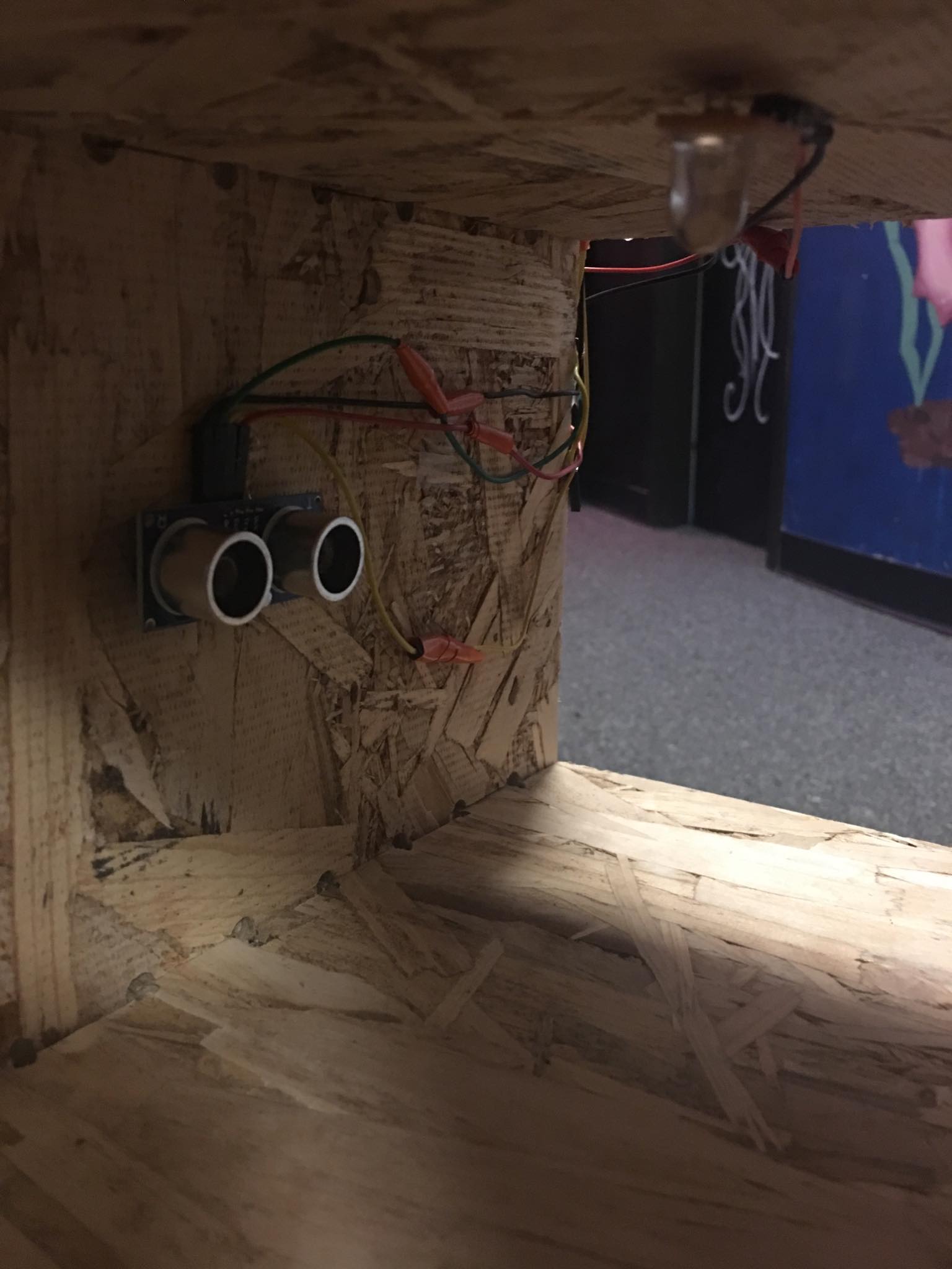
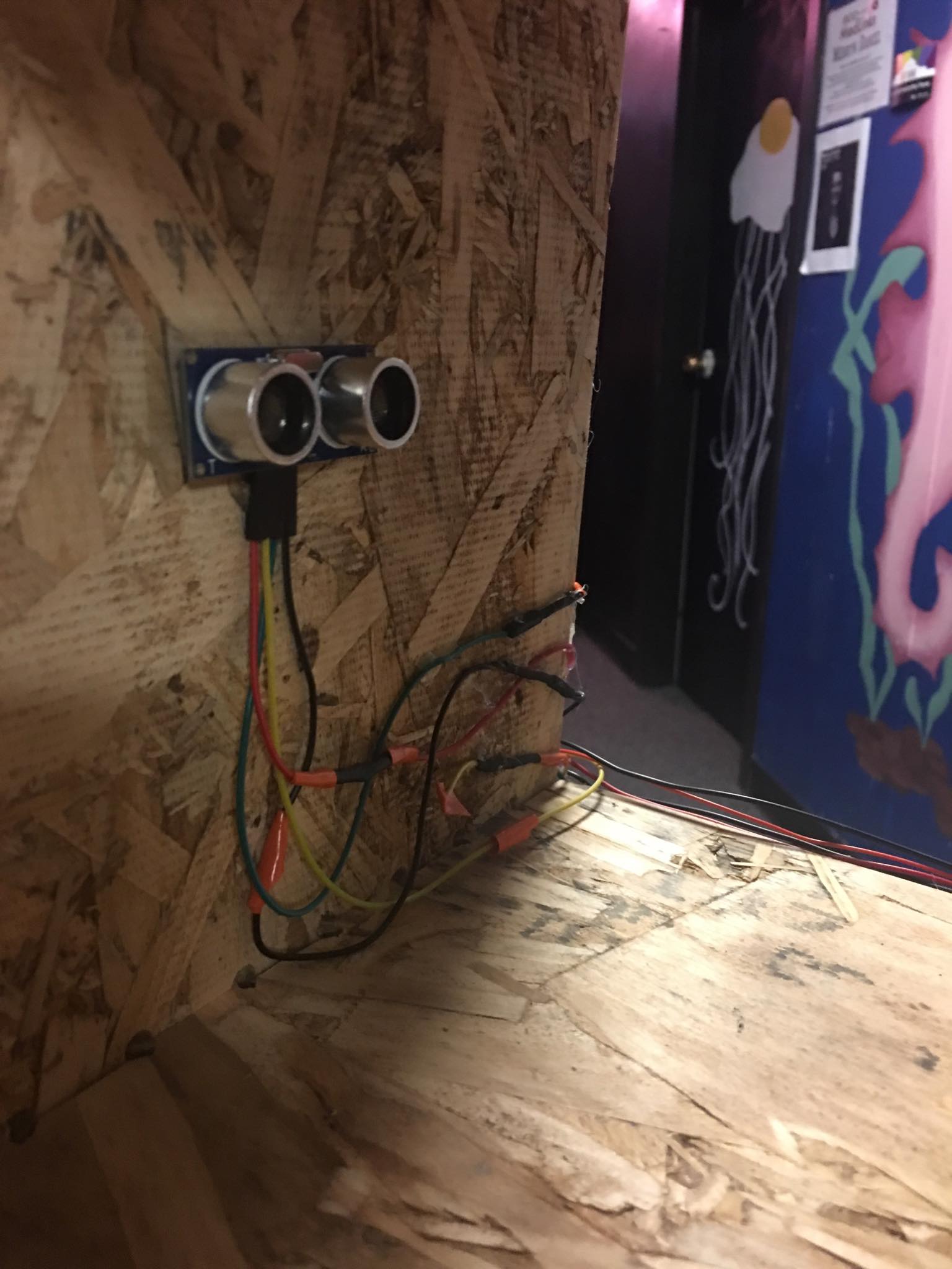
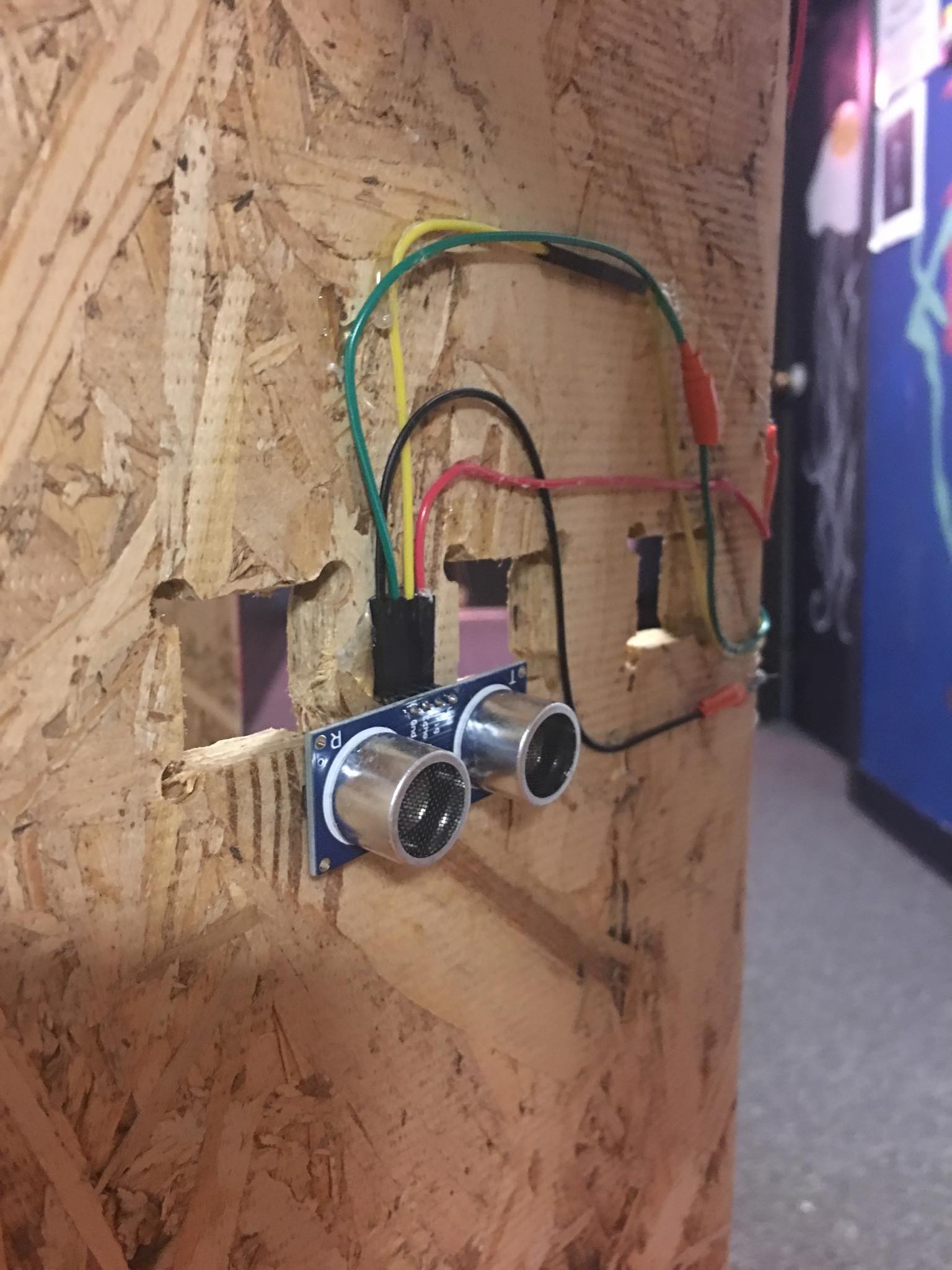
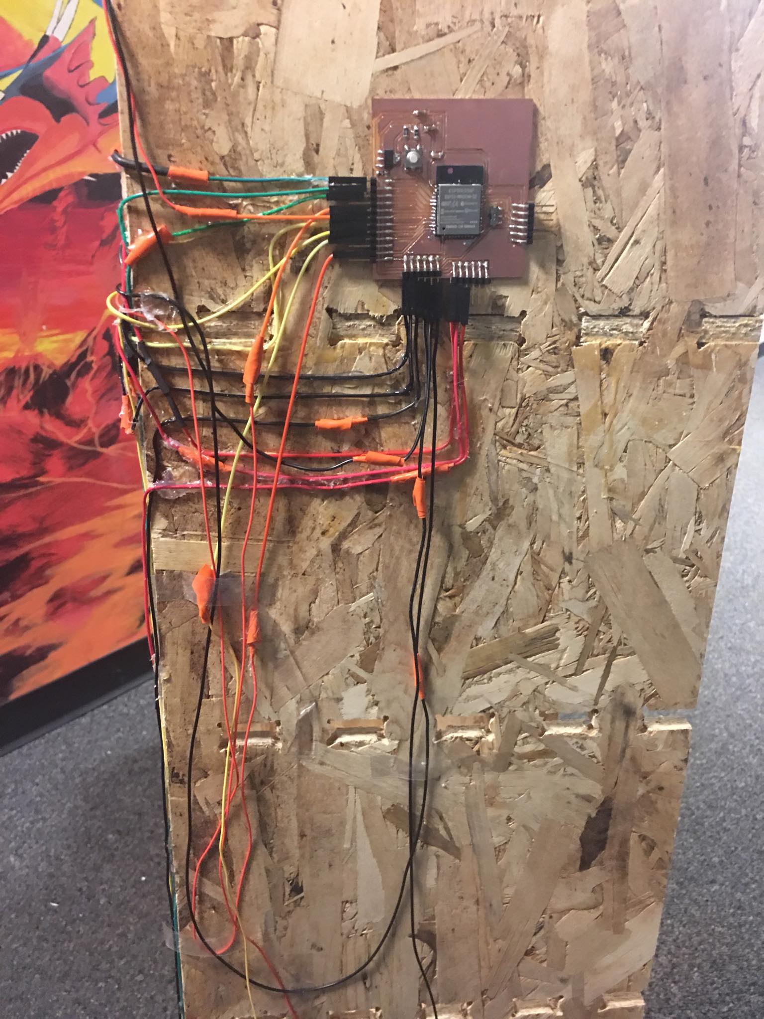
Now that I had my frame for my compartments that would house my electronics, it was time to design the electronics I would need. I decided to use 3 ultrasonic sensors and 3 light boards to go along with them and I wanted the controller to be able to send and receive information be it over WiFi or Bluetooth. Additionally in order to be able to control 6 of these parts, I realized I needed a controller with a lot of pins. With these considerations in mind, I designed an ESP32 board (Documentation Here).
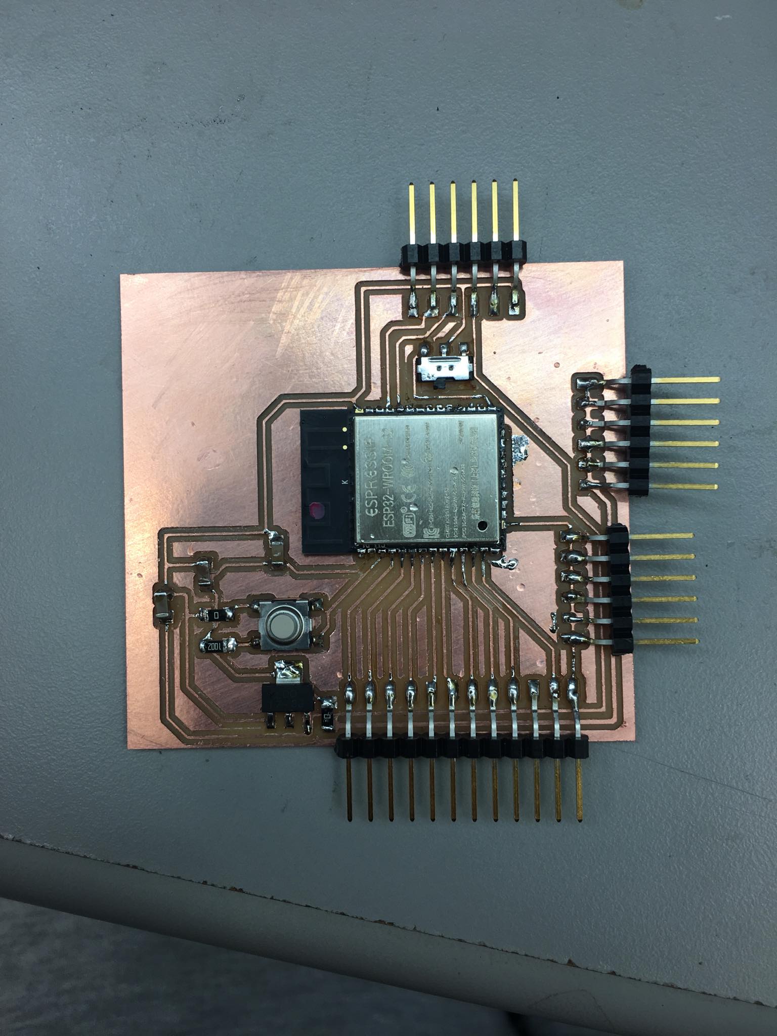
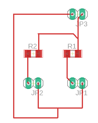
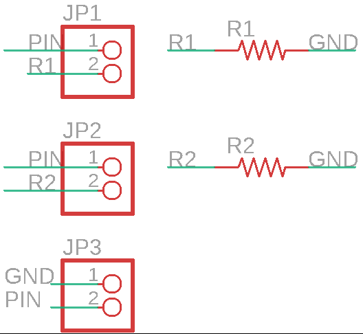
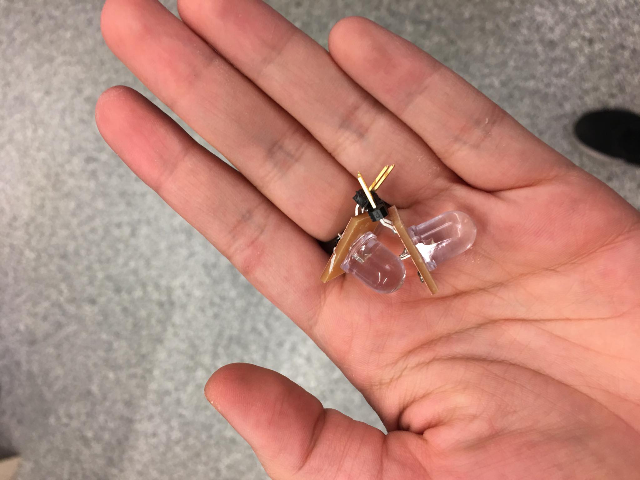
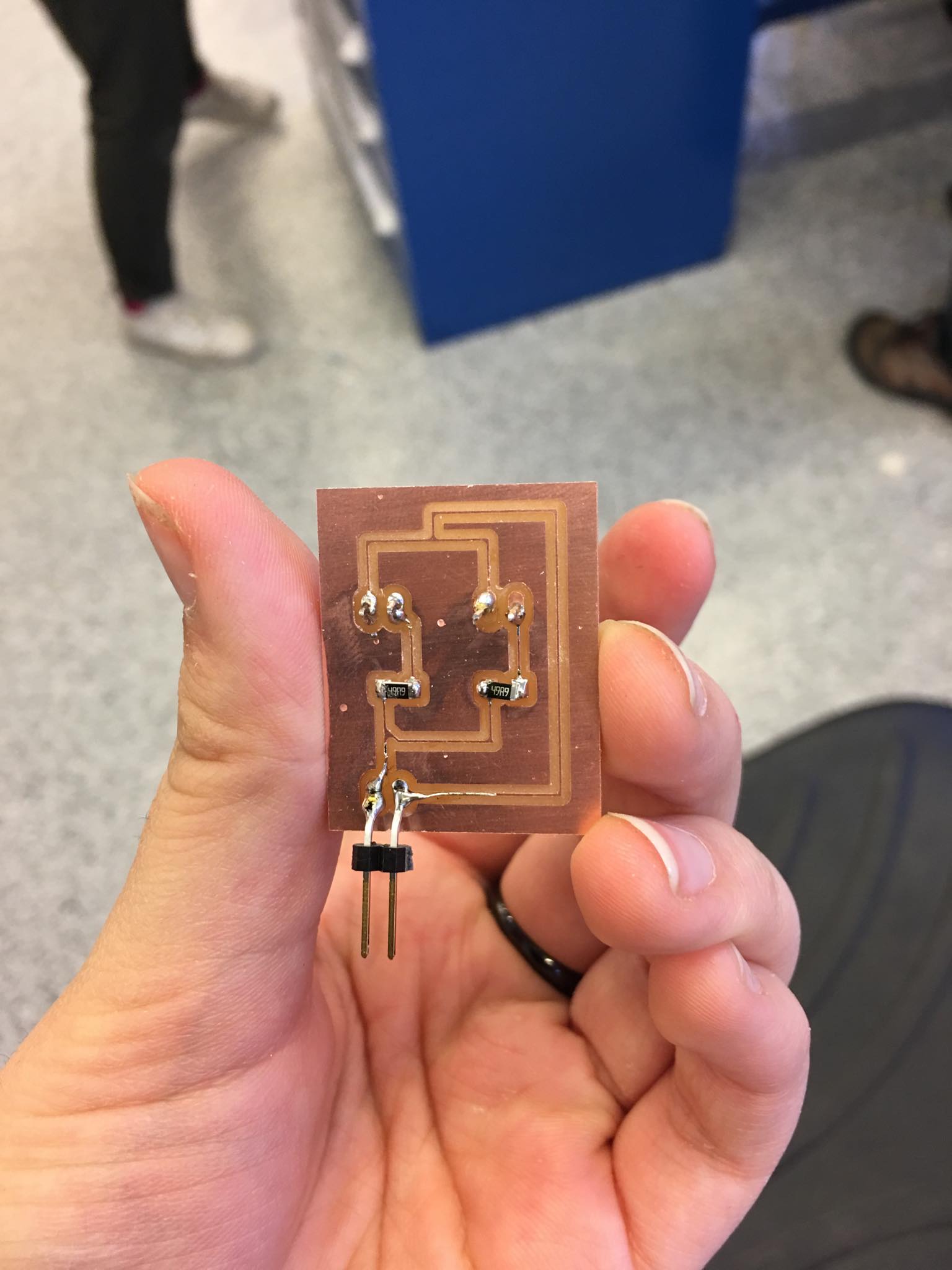
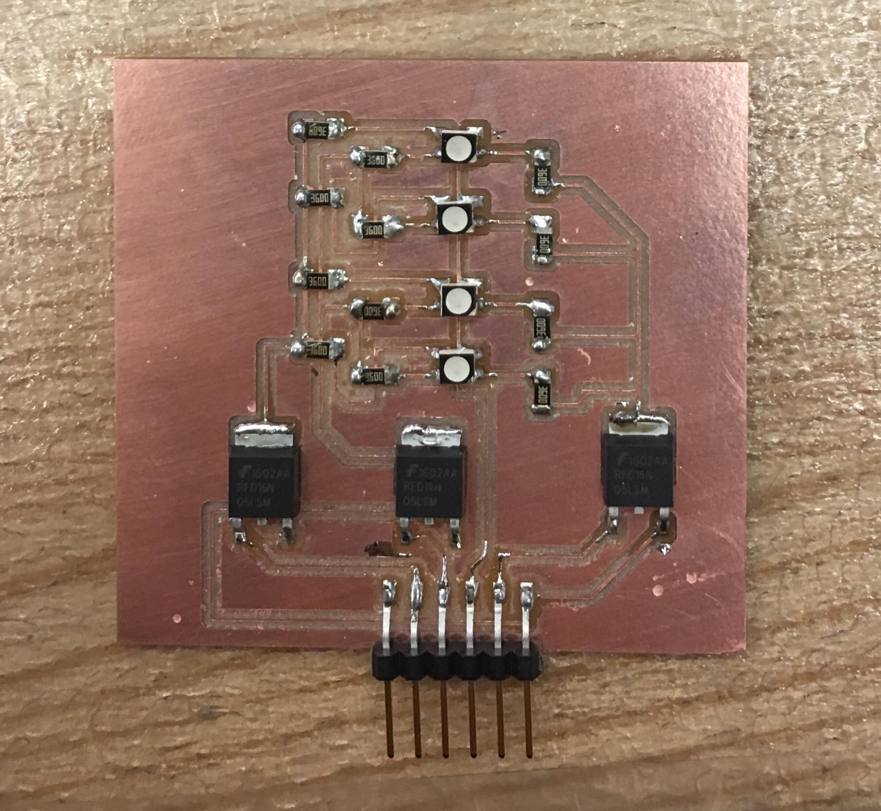
Now that I had a board that could successfully connect all of the electronics I needed it to connect. I could focus on the electronics that it would connect to and control. The ultrasonic sensors (HC-SR04) were provided to me so I didn't need to worry about creating them. However, I needed a way to shine lights. I then created three different light boards. 2 of these boards utilized white LEDS and the other board was a 4 RGB LED boards controlled by a N-type mosfet.
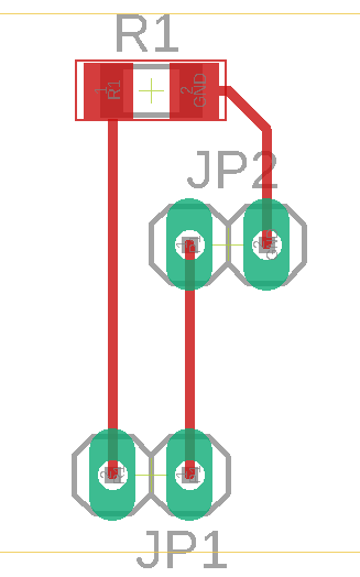
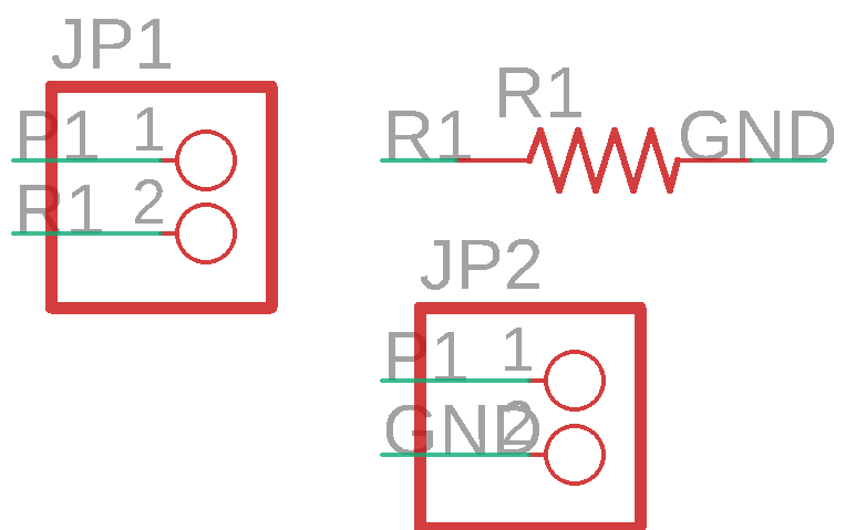
The board schematic for the white LED boards are shown below along with the final products. ( I accidentally made a mistake calculating the resistance of the resitors in parallel... ( I thought the voltage split so the LEDs ended up being a lot dimmer than expected for the 2 LED board). I hot aired the board and reattempted with the correct calculation ((3.3 (my power)-3 (optimal power)) )/.02 (current)=R=~15 Ohms, thus I used a 10 Ohm resistor, with the LEDs, and a 2 pronged header.
The 4 RGB LED board was created as a part of my output devices week (Documentation Here).
Testing
Ultrasonic Sensors
I began testing my product and I ran into a couple of issues with the ultrasonic sensors. First off when an object is very close to the sensor it will read an extremely high value and I needed to account for this in the code. Additonally the way I had originally set up my board was that every ultrasonic sensor would be triggered at the same time and could share a trigger pin. However, the sensors were interfering with each other and would give consistently very off numbers. In order to fix this I unspliced the wires and wired every sensor to its own trigger pin and the sensors now function as expected!
User Interface and Web Server
I then began testing the web server and initial user interface without light integration and the next test with light boards will integrate all parts of the project together!
Light Boards
Unfortunately none of the light boards work as intended except for the output one, which only turns on in programming mode.
Embedded Programming and Interface and Application Programming
Now that all my electronics were done I needed to program the electronics so that they would function as expected. After I conducted all the test shown above and verified that my program was working, my code is:
//
// hello.ESP32-WROOM.WebServer.ino
//
// ESP32 Web server checkShelves
//

#include <WiFi.h>

const char* ssid = "MIT GUEST";
const char* password = "";
WiFiServer server(80);

const int ECHO1=36;
const int FDISTANCE1=14;
const int TRIGGER1=26;
const int LED1=35;

const int ECHO2=39;
const int FDISTANCE2=14;
const int TRIGGER2=25;
const int LED2=32;

const int ECHO3=34;
const int FDISTANCE3=14;
const int TRIGGER3=27;
const int LED3=14;

const int SIZE=3;
int echoPins[] = {ECHO1, ECHO2, ECHO3};
int expectedDistances[]={FDISTANCE1, FDISTANCE2, FDISTANCE3};
String echoStates[3];
int triggerPins[]={TRIGGER1, TRIGGER2, TRIGGER3};
int LEDPins[]={LED1, LED2, LED3};

String html="";

void setup() {
  pinMode(TRIGGER1, OUTPUT); // Sets the trigger as output
  pinMode(TRIGGER2, OUTPUT);
  pinMode(TRIGGER3, OUTPUT);

  pinMode(LED1, OUTPUT);
  pinMode(LED2, OUTPUT);
  pinMode(LED3, OUTPUT);

  for (int i = 0; i < SIZE; i = i + 1) {
    pinMode(echoPins[i], INPUT);
  }

  Serial.begin(115200);
  webServerSetup();
}

void loop() {
  //String visualized=updateAll();
  //Serial.println(visualized);
  webServer();
}

String updateAll(){
  String visualization="";
  for (int i = 0; i < SIZE; i = i + 1) {
    // Clears the trigPin
    digitalWrite(triggerPins[i], LOW);
    delayMicroseconds(2);

    // Sets the trigPin on HIGH state for 10 micro seconds
    digitalWrite(triggerPins[i], HIGH);
    delayMicroseconds(10);

    digitalWrite(triggerPins[i], LOW);
    // Reads the echoPin, returns the sound wave travel time in microseconds
    long duration = pulseIn(echoPins[i], HIGH);
    // Calculating the distance
    long distance= duration*0.034/2;
    delayMicroseconds(10);

    //lights don't work :( can't figure out why only connected to RGB at the moment
    String empty="Empty";
    // when things too close to sensor or tilted adds some distance
    digitalWrite(LEDPins[i], HIGH);
    if(distance<expectedDistances[i]){
      empty="Not empty!";
      //digitalWrite(LEDPins[i], LOW);
    }
    else{
      //digitalWrite(LEDPins[i], HIGH);
    }
    echoStates[i]=empty;
    visualization+="cabinet: ";
    visualization+=echoPins[i];
    visualization+=" status: ";
    visualization+=empty;
    visualization+=" distance: ";
    visualization+=distance;
    visualization+="<br>\n";
  }
  return visualization;
}

void webServerSetup(){
  printf("\nConnecting ");
  WiFi.begin(ssid,password);
  while (WiFi.status() != WL_CONNECTED) {
    delay(100);
    printf(".");
    }
  printf("\nConnected with address %s\n",WiFi.localIP().toString().c_str());
  server.begin();
}

void webServer(){
  char cold,cnew;
  WiFiClient client = server.available();
  if (client) {
    printf("\nReceived connection from %s\n\n",client.remoteIP().toString().c_str());
    while (client.connected()) {
      if (client.available()) {
        cnew = client.read();
        printf("%c",cnew);
        if ((cold == '\n') && (cnew == '\r')) { // check for blank line at end of request
          client.printf("HTTP/1.1 200 OK\n");
          client.printf("Content-type:text/html\n");
          client.println("Refresh: 5");
          client.println("<!DOCTYPE HTML>");
          client.println("<html lang='en'>");
          client.println("<head>");
          client.println("<meta charset='utf-8'>");
          client.println("<title>Smart Steps</title>");
          client.println("</head>");
          client.println("<body>");
          client.println(html);
          client.println(updateAll());
          client.println("</body>");
          client.println("</html>");
          client.flush();
          client.stop();
          break;
          }
        cold = cnew;
        }
      }
    }
}
Overall Assembly
To assemble the final model together I stuck the main ESP32 board onto the side of the staircase were it would be easily accessible with double sided tape and I hot glued the female ends of the jumper cables onto the sides and tops of the compartments where the ultrasonic boards and the light boards would attach. I then soldered together the jumper cable ends and the wires such that they would extend to the right places, wired the electronics, and hot glued the wires to the side of the staircase so that it would look cleaner.
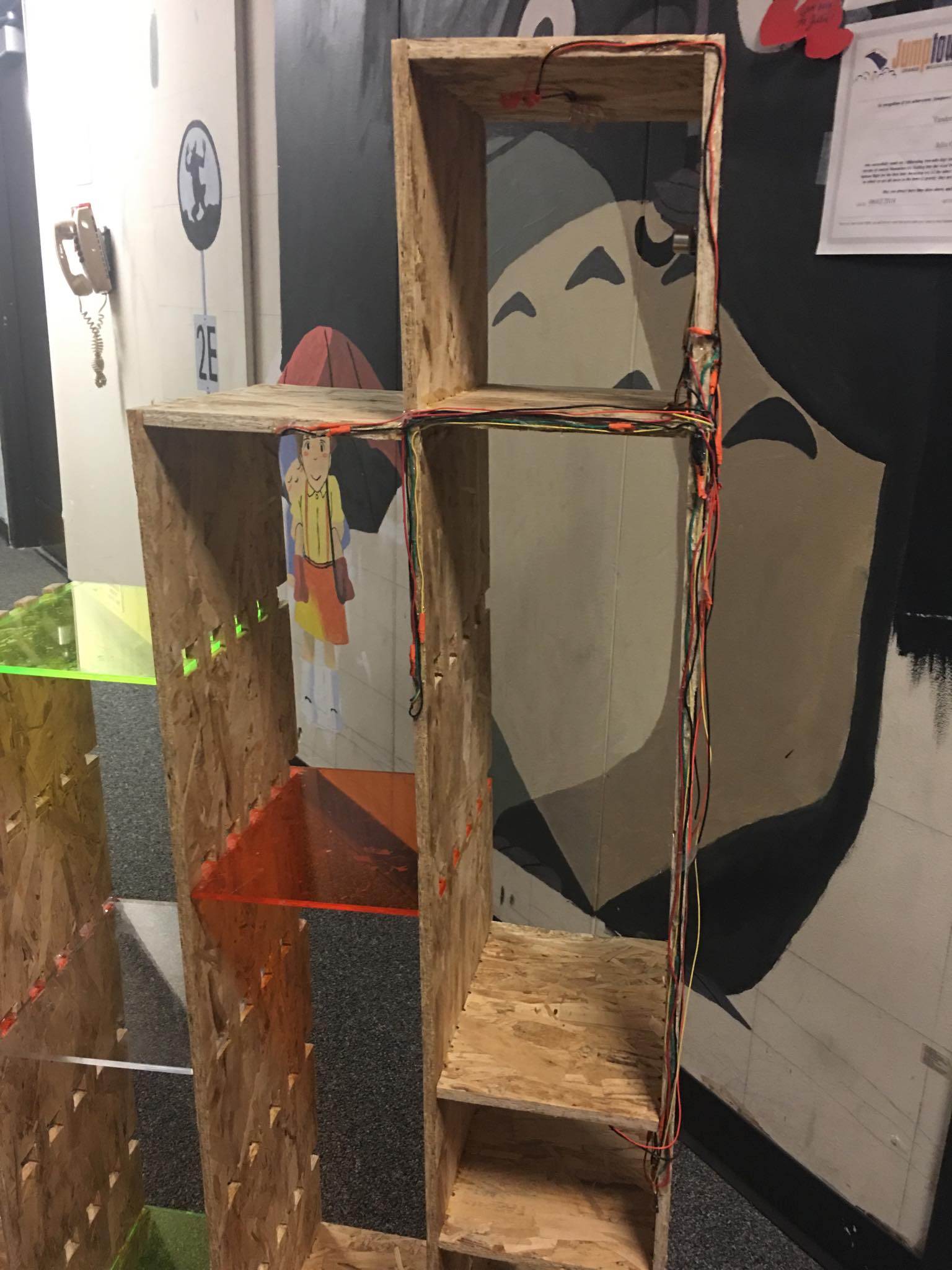
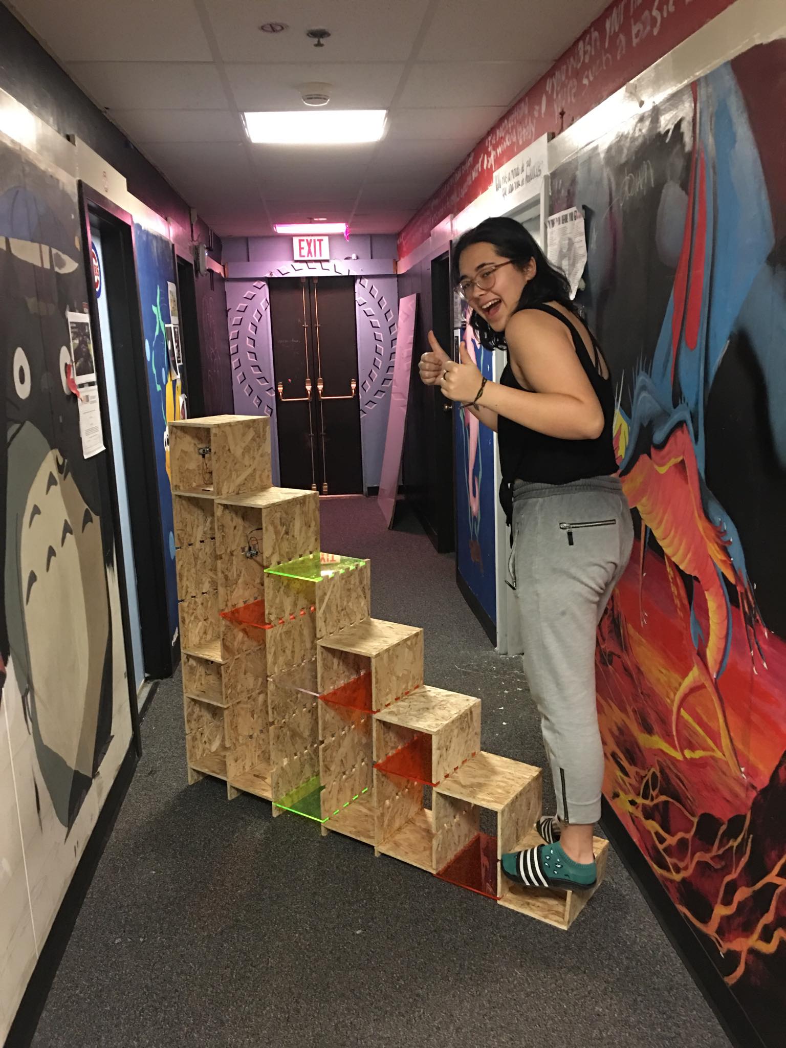
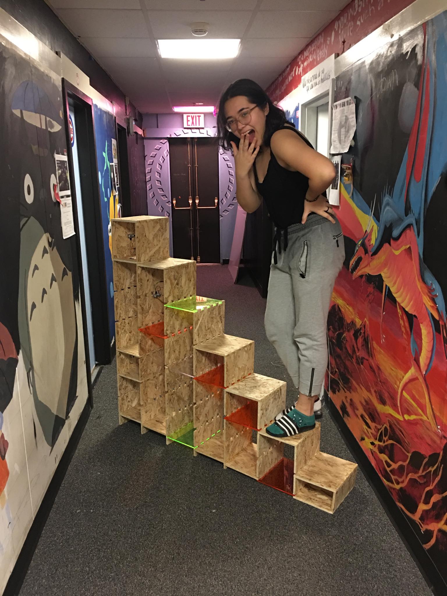
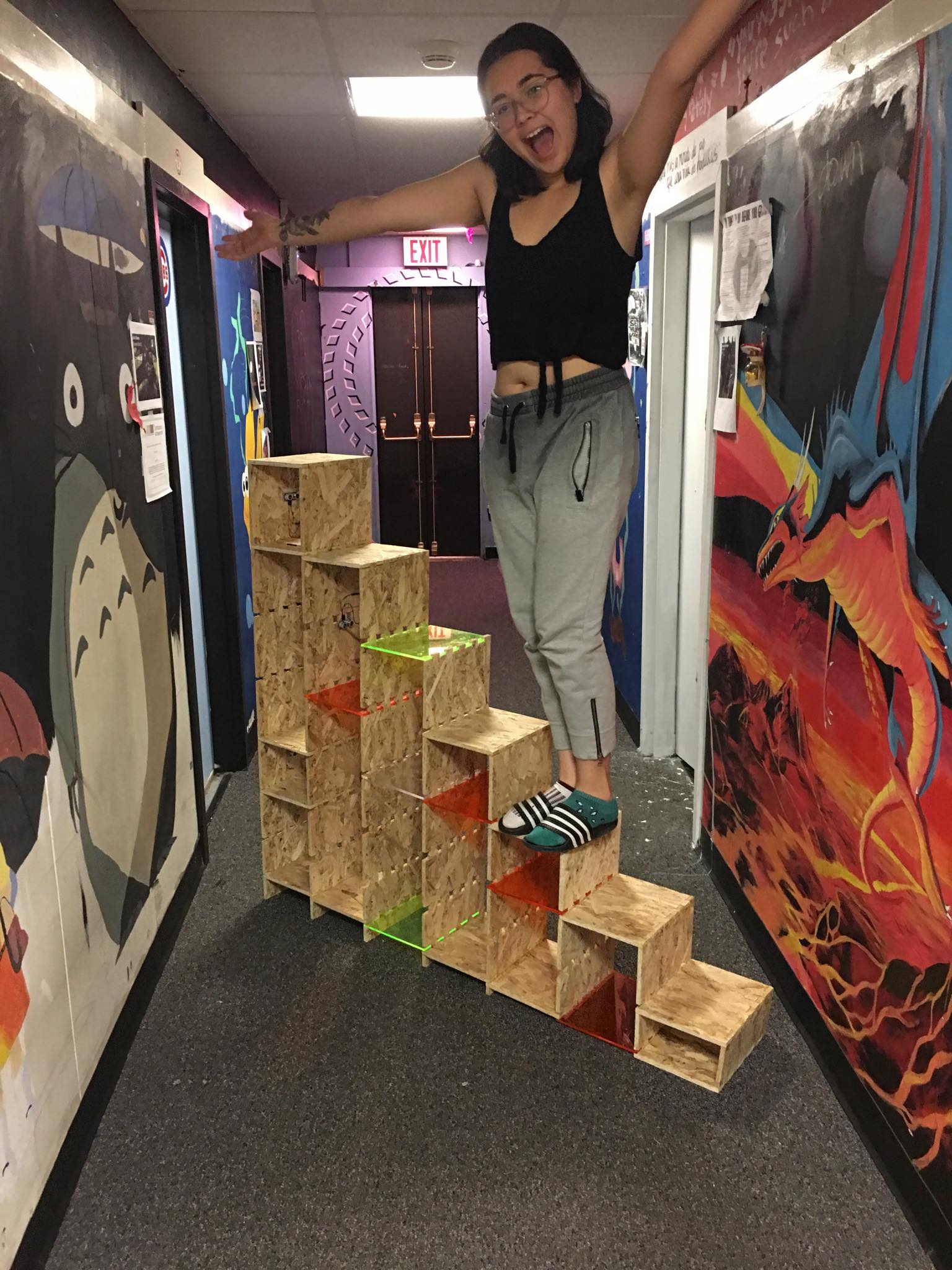
Final Product
Project Implications/Reflections
The project will make it easier for me to paint different parts of my room and serve as a nice place for storage. The lighting is also very nice. Keeping track of inventory is also an important issue in labs as people often take the last part without notifying anyone which can sometime result in a shortage of a part for some time. Having a sensor to keep track of inventory can be very useful in many settings.
Moving forward I think I would like to work more on making the lights work. I would really like to be able to also improve the interface for understanding whether a compartment is empty or not. At the moment my output device is currently only turning on when the esp32 is not running, when it is in program mode. Hopefully I will be able to debug this.
I learned a lot from this project mostly in terms of CAD design as well as how to design different electronics. Another thing I picked up was learning how to program electronics and the many nuances of timing that can make code that seems correct, incorrect.
Parts List
| Quantity | Material | Sourced From | Total Price |
|---|---|---|---|
| 1 | 4'x8' OSB Sheet | Arch Shop | |
| 4 | 24"x12" acrylic sheet | EDS Materials | |
| 3 | HC-SR04 Sensors | EDS Materials | |
| 6 | FTDI Headers | EDS Materials | |
| 1 | ESP32 WROOM | EDS Materials | |
| 1 | 1 mf Capacitor | EDS Materials | |
| 1 | 10 mf Capacitor | EDS Materials | |
| 1 | .1 mf Capacitor | EDS Materials | |
| 3 | 10 Ohm Resistor | EDS Materials | |
| 1 | 10K Ohm Resistor | EDS Materials | |
| 2 | 0 Ohm Resistor | EDS Materials | |
| 1 | 3.3V 1Amp Voltage Regulator | EDS Materials | |
| 1 | Button Switch | EDS Materials | |
| 1 | 12V Switch Slide | EDS Materials | |
| 3 | 1 Sided Copper PCB | EDS Materials | |
| 4 | White LEDs | EDS Materials | |
| 4 | RGB LEDs | EDS Materials | |
| 12 | 360 Ohm Resistor | EDS Materials | |
| 3 | N-Type Mosfet | EDS Materials | |
| 1 | 30 ft of wire | EDS Materials | |
| 1 | Pack of Jumper Cables | EDS Materials |