Electronics Design
Recreating the echo hello-world Board
We observed how a multimeter could show the connections between different traces and ensured the traces were still in place. For the individual assignment I redrew the echo hello-world board that Neil designed and added a button and LED with a pull up resistor, made the board and tested it.
Redesigning the echo hello-world Board
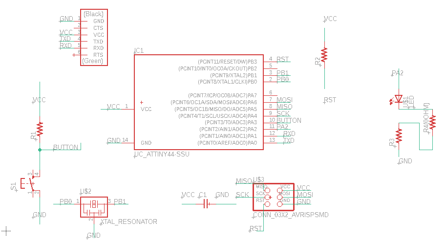
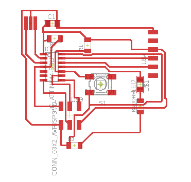
I struggled a little bit with laying out all of the components in the board and eventually I gave in and decided to use a 0 ohm resistor to make things easier. My board schematic and design are above!
Milling and Soldering

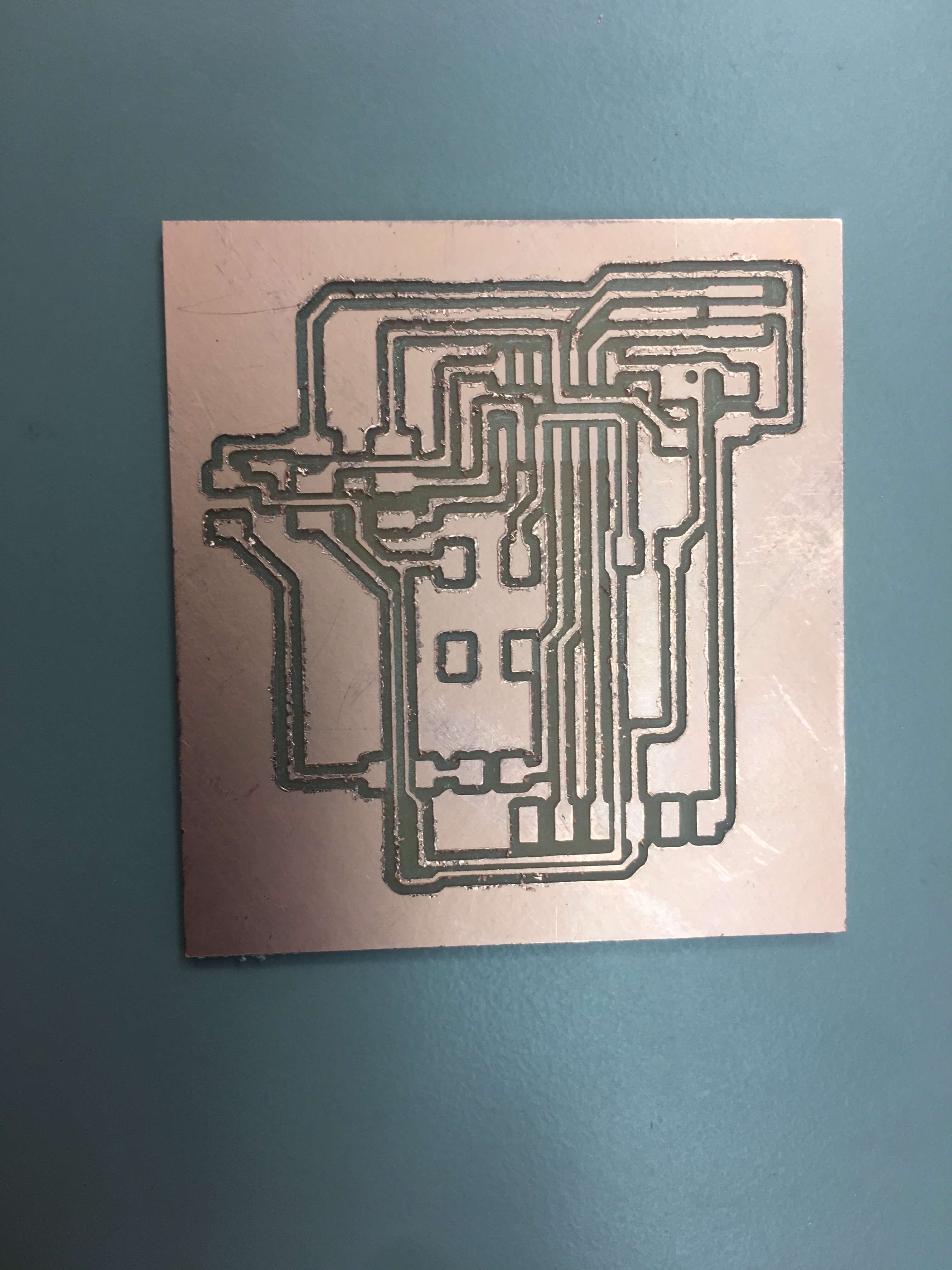
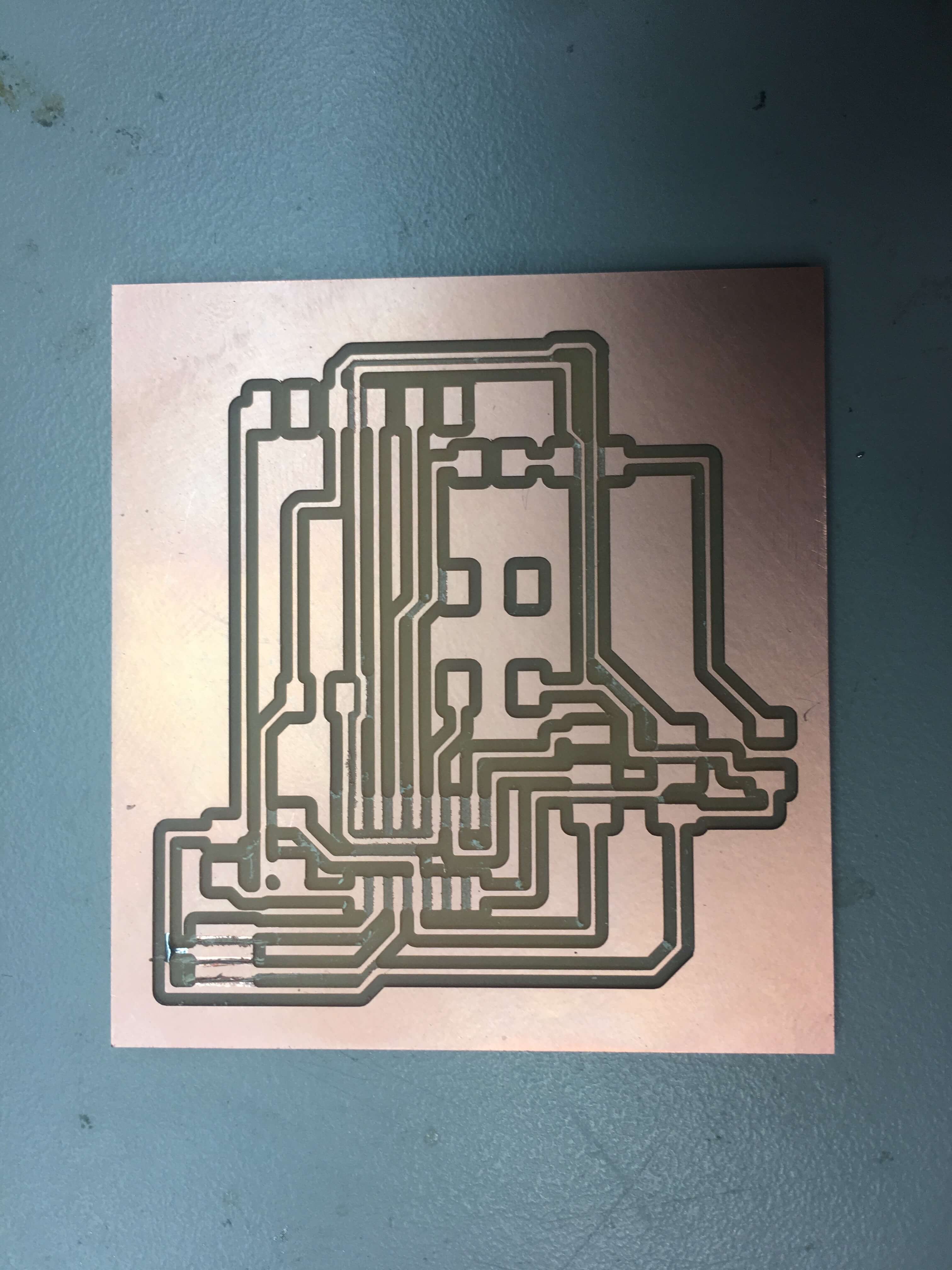
The first time I tried to mill the board the 1/32 end bit was dull so the borders of the traces were extrememly jagged and raised. I tried to tweeze and scrape parts off but it didn't help too much. I made the deicison to remill. However unfortunately this time, while the milling was much cleaner it didn't mill all the way through the copper where the resonator is. I used an exacto knife to cut through it so it wouldn't be electronically connected (this unfortunately becomes a problem later). I accidentally cut through a trace that I ran solder through to reconnect it.
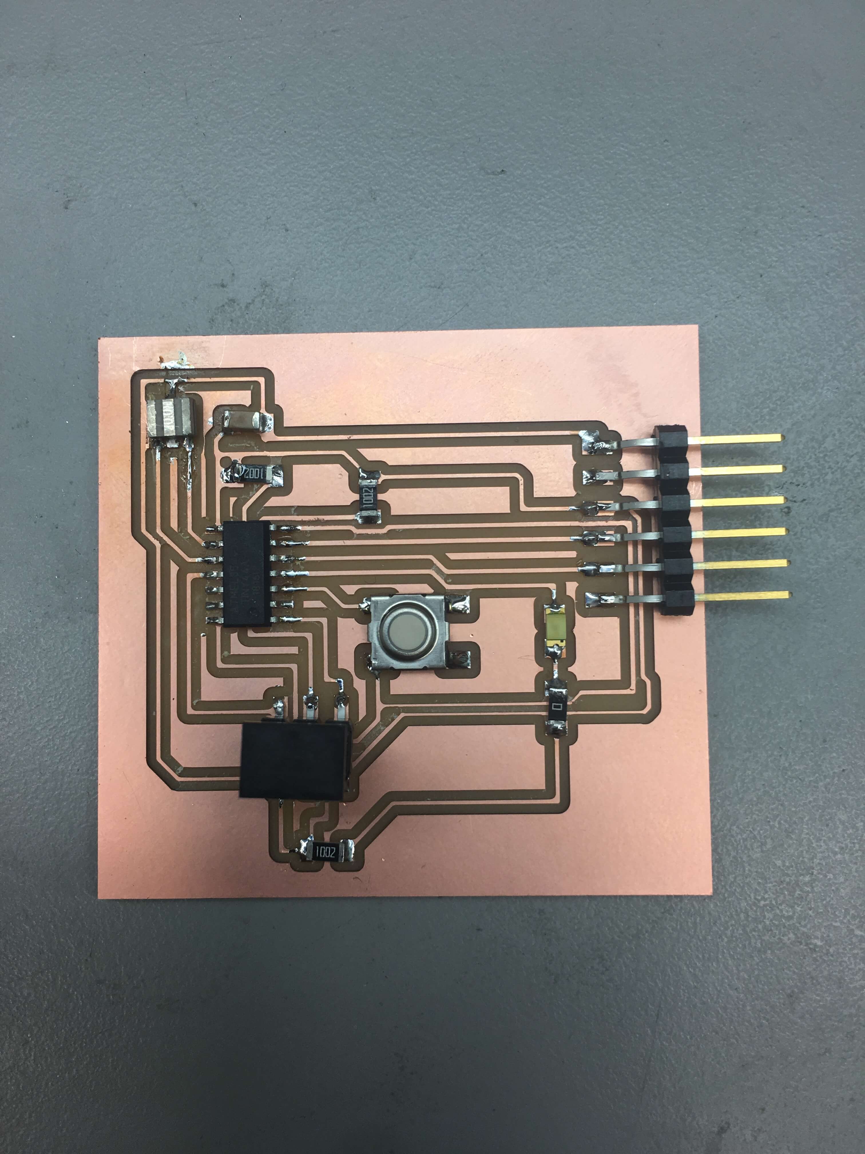
I solder these components on and accidentally solder the resonator on in the wrong direction. I use hot air to remove it and lift up a trace in the process. I resolder the trace and the board is complete
Testing the Board
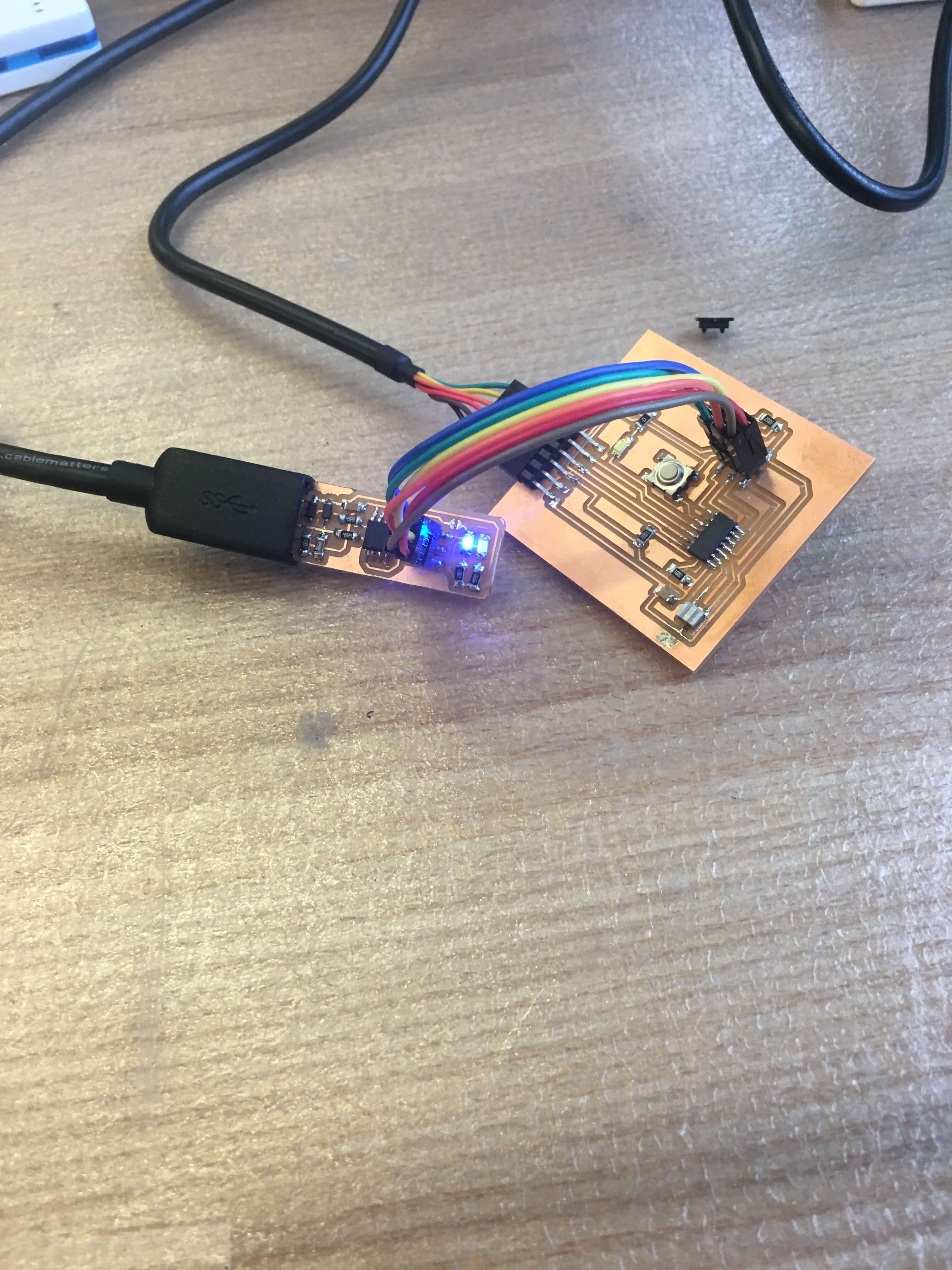
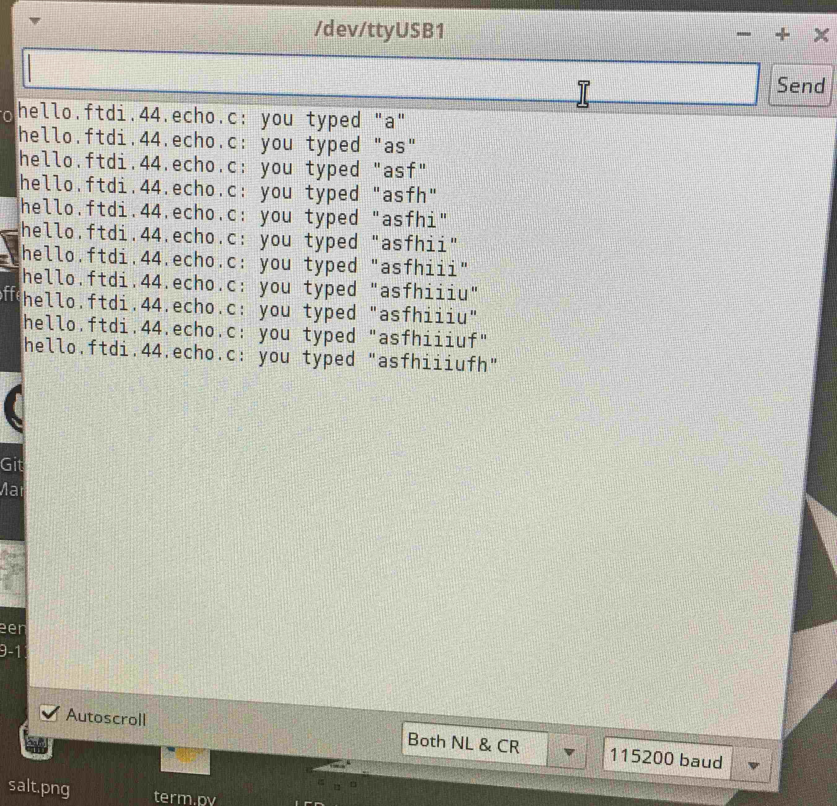
I go to test the board and the board is dead. I use the multimeter and find out the part on the resonator that is supposed to go to ground is not going to ground. It turns out the trace I ripped through knifing did not get soldered together, I resolder and the connection works. I retest the board by trying to upload code and it is still dead as one of my joints wasn't connected correctly. I go back again and I'm still getting an error. After looking at some common sources of the rc=-1 error, I realize that I soldered the attiny 44 with pin 1 in the wrong spot. I remove the attiny 44 with hot air and resolder. This time the board was succesfully programmed with Neil's code!
Known causes of the rc=-1 error (Courtesy of Jake Read):
- Programming cable is oriented correctly. (A Brian-pattern FabTiny will light up bright red if connected correctly, and dim red if connected incorrectly.)
- Board is milled correctly (traces are properly isolated).
- No shorts between power and/or data lines.
- No open circuits between t44 pins and corresponding connector pins.
- Solder joints are in good condition.
- No unintended solder bridges between adjacent pins / traces.
- t44 is oriented correctly on board (check pin 1 indicator).
- Required clock source is present on board (depending on how you set fuses) and in good condition.
- Corollary, if you're confused: You are using the correct Makefile for the example board you started from, if any. (Some example boards have a 20 MHz external oscillator while some do not. Pay attention to which variant your "base" board is!)
- No swapped data signals. (For instance, verify that MOSI goes to MOSI and MISO goes to MISO.)
- Programmer is in good condition (does it talk to a known-good board? if FabTiny, did you make rstdisbl?).
- Computer is in good condition (does switching computers produce a different result?).