Input Devices
Creating a Sound Board
Redesigning the Sound Board


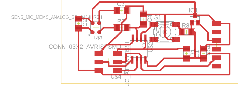
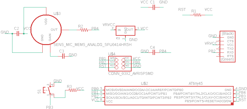
For this week I took the analog MEMS sound board on the fab website and added an LED button to it to exert some more control over it in the future. The components required for this board are:
- 1 c1 1 mf
- 1 c2 .1 mf
- 1 c3 10mf
- 1 c4 .1 mf
- 1 3.3 V voltage regulator
- 1 ISP Header
- 1 attiny 45
- 1 FTDI header
- 1 button
- 1 r1 10k Ohms
- 1 r2 1k Ohms
- 1 r3 10k Ohms
- 1 analong MEMS microphone
Notes:
- ISP - how you load code onto the microcontroller
- rst needs to be high all the time for the microcontroller to work except for when you're programming rst low
- bypass capacitors- c1 c2, nice to throw on vcc lines, suppresses noise
- c4 and r2 reduce the high frequency (cell phones ghz noise)
- for these things to reduce ELECTRONICS noise well, they should be as close as possible
Milling and Soldering


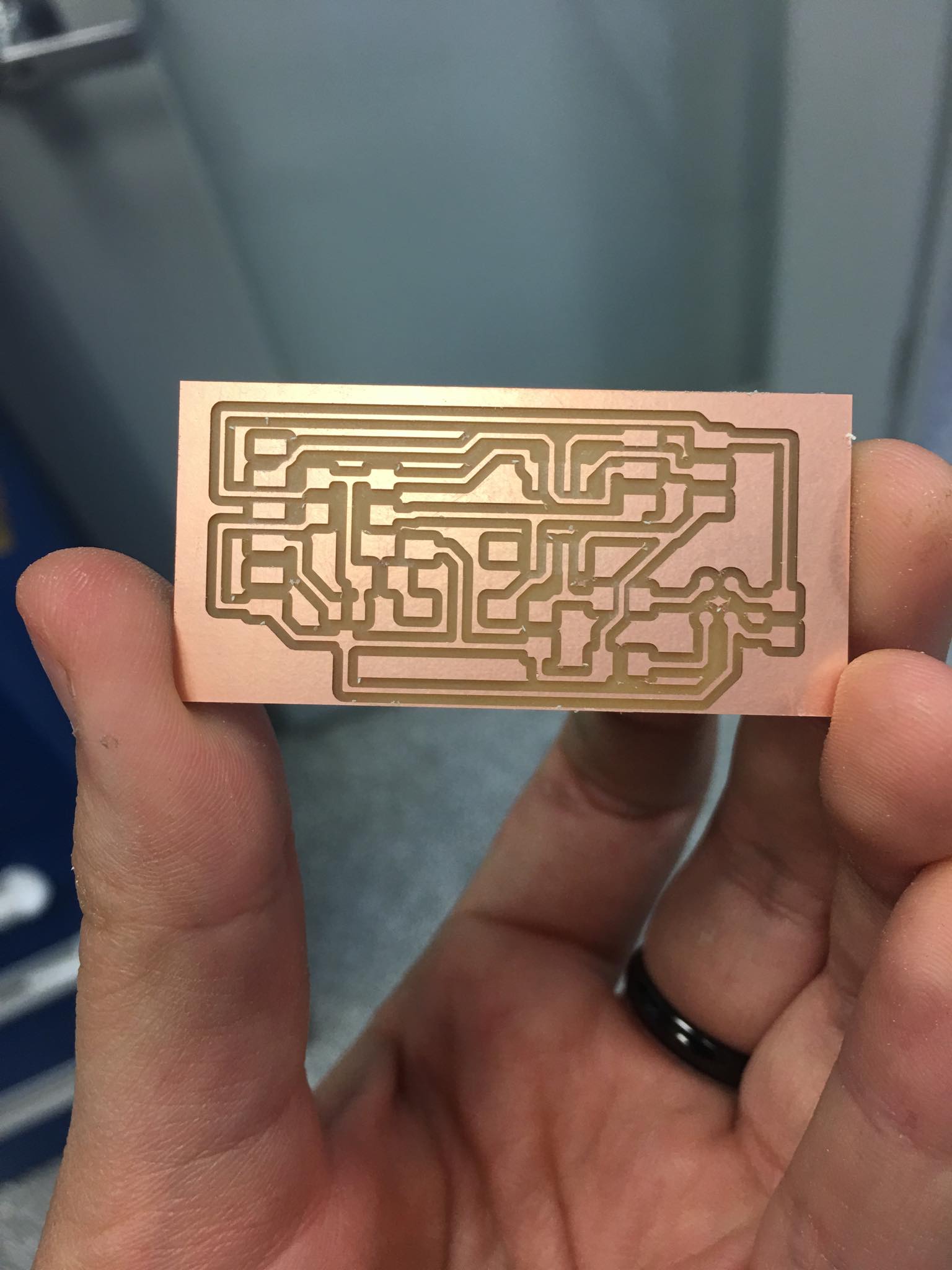
Using the above schematic I milled and soldered the board.
Programming
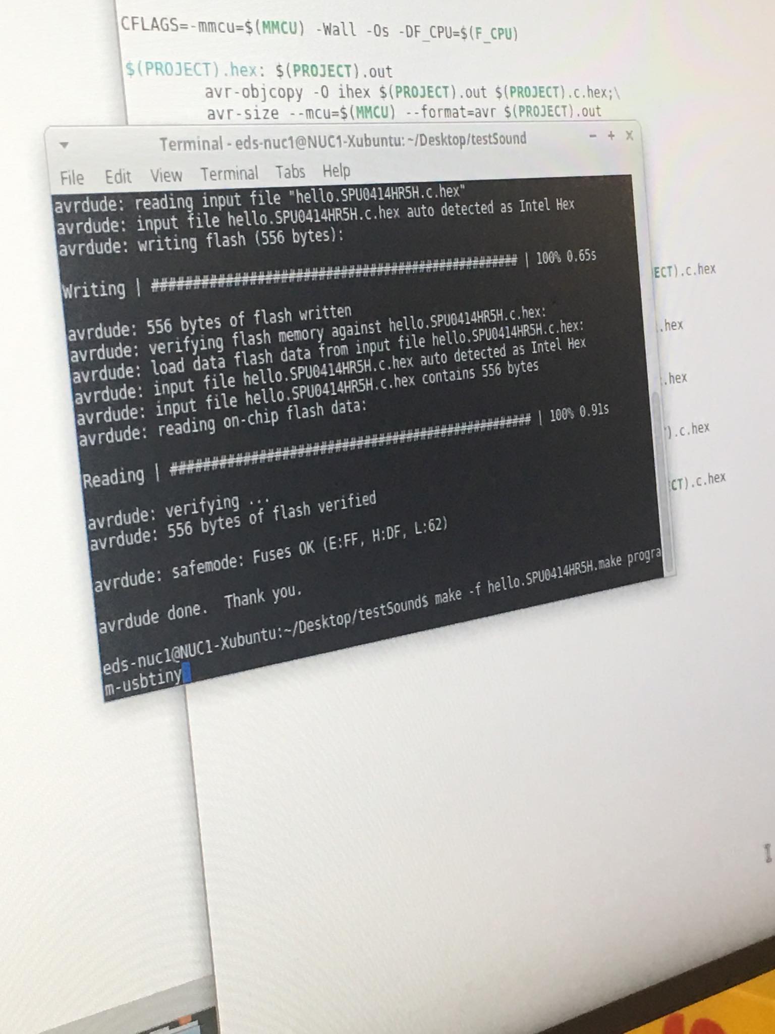
Using Neil's code I uploaded the make file, c file and the python script. It would be nice to utilize the button in the future to decide when to turn the mic on and off as well as to interface somehow between sound and light, using some sort of signal processing.
