Output Devices
Creating a LED Board
Designing the Board
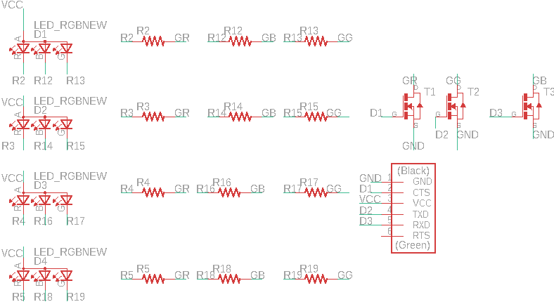

I wanted this board to feed directly into my final project and so it does not have a microcontroller directly on the board as it will be controlled by my esp32 board that I created for the networking week. I decided to use N-type mosfets to control 3 channels that would determine the R, G, B values for the LED lights. The esp32 does not have analog built in automatically so at the moment it is currently able to produce 8 different colors based on the HIGH/LOW combinations of the RGB channels.
The board components are:
- 4 RGB LEDs
- 12 360 Ohm resistors (3 per LED for each channel)
- 3 N-type mosfets
- 1 FTDI header (for the footprint, not configured like the FTDI)
Milling and Soldering
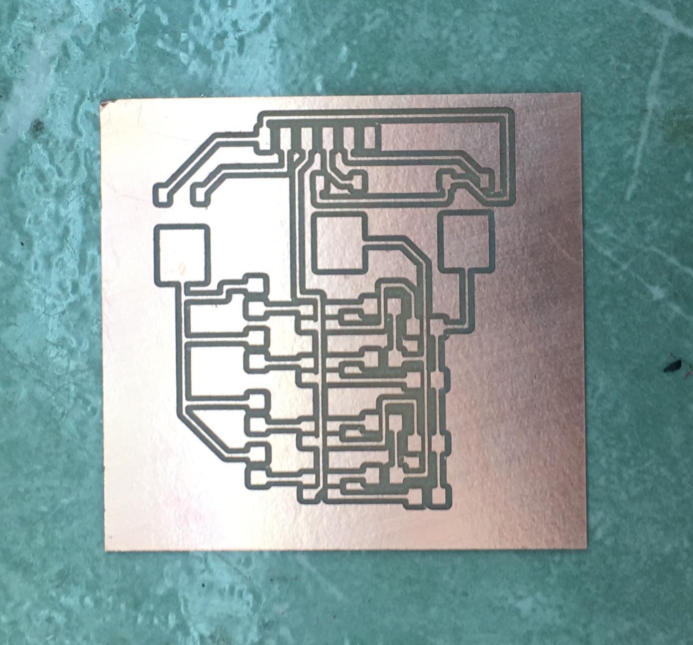
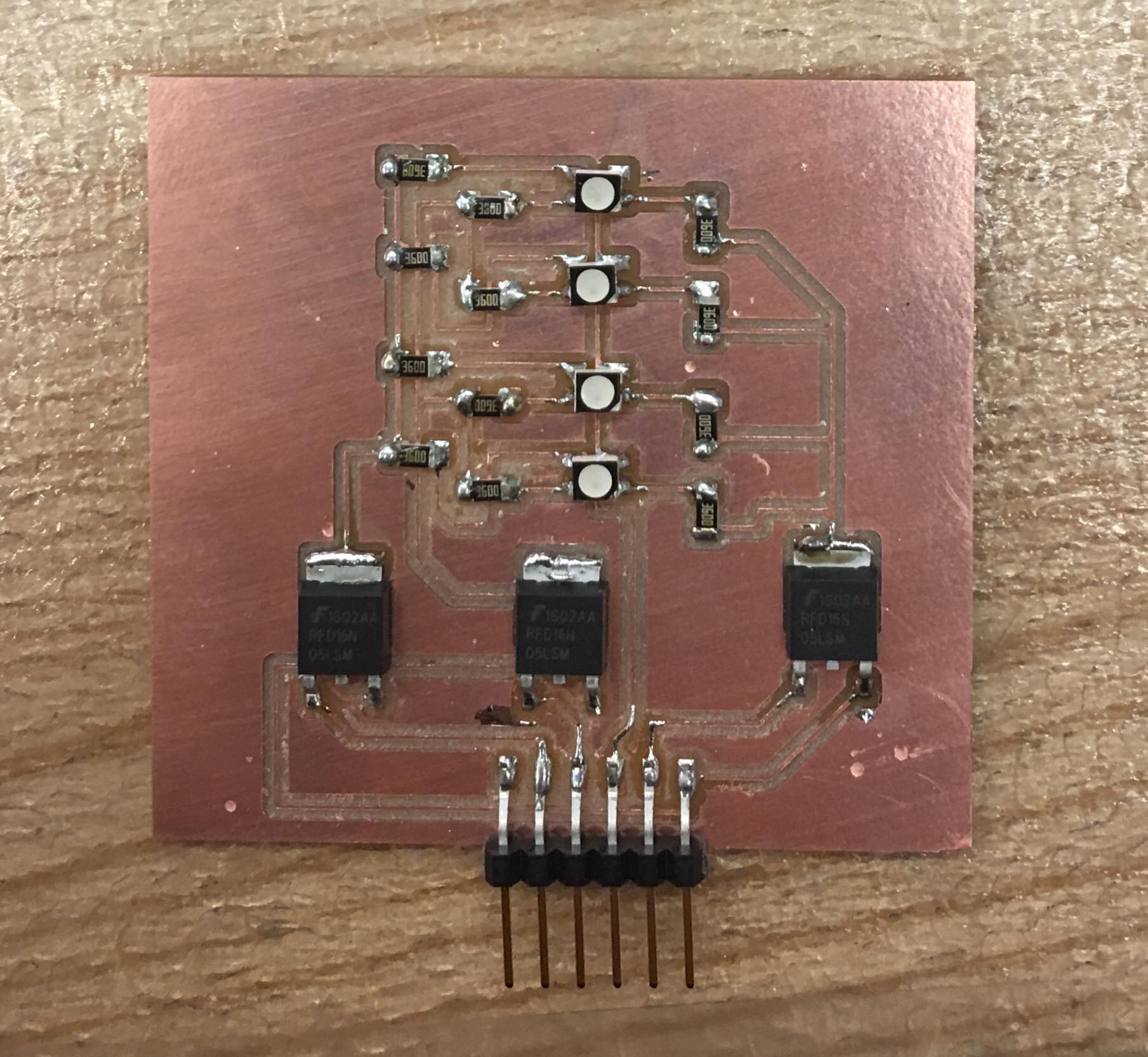
I milled and soldered the board according to the schematic above.
Testing the Board
I first tested the board in lab by hooking it up to a power supply and running current through different channels to test the RGB functionality. THe brightness was higher than I expected, which was pleasantly surprising.
Programming the Board
The board was "programmed" by the esp32 board that set the pins to high and low (controlling the color and whether the lights were on and off) depending on the output of the ultrasonic sensors in my final project. The full documentation for this can be found on my final project page.