Networking and Communications
Creating an ESP32 Board
Designing the Board

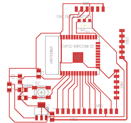
I wanted to integrate this week into my final project by making this the main board that connected everything. I am using ultrasonic sensors in my final project to sense whether a space is empty or not as well as integrating lights that would turn on and off based off of the value of these sensors and interface with a website to display to the user. In order to do this and make it easier for myself I designed a board with various VCC and GND pins to avoid splicing and soldering more wires than I needed to to form connections, as well as multiple IO pins and output devices like the ultrasonic sensors and the LED lights. One mistake I made in this initial design was designating only one trigger for all the ultrasonic sensors, which is something I learned was bad when trying to integrate everything in the project. This was easily fixed by just using the other IO pins (they just weren't marked as trigger in the schematic).
In order to add the proper footprint to the board I visited here and searched the esp32 wroom and downloaded the footprint. I then imported this into Eagle and changed the footprint to 31 mm to match the esp32 we have at EDS. The components needed for this board are:
- 1 esp32 wroom
- 3 6 pin headers (FTDI headers)
- 1 12 pin header (2 FTDI headers together)
- 1 1mf capacitor c2
- 1 10mf capacitor c1
- 1 .1 mf capacitor c3
- 1 10k ohm resistor r1
- 2 0 ohm resistor
- 1 3.3 volt 1 amp voltage regulator
- 1 button switch
- 1 12 v switch slide
Milling and Soldering

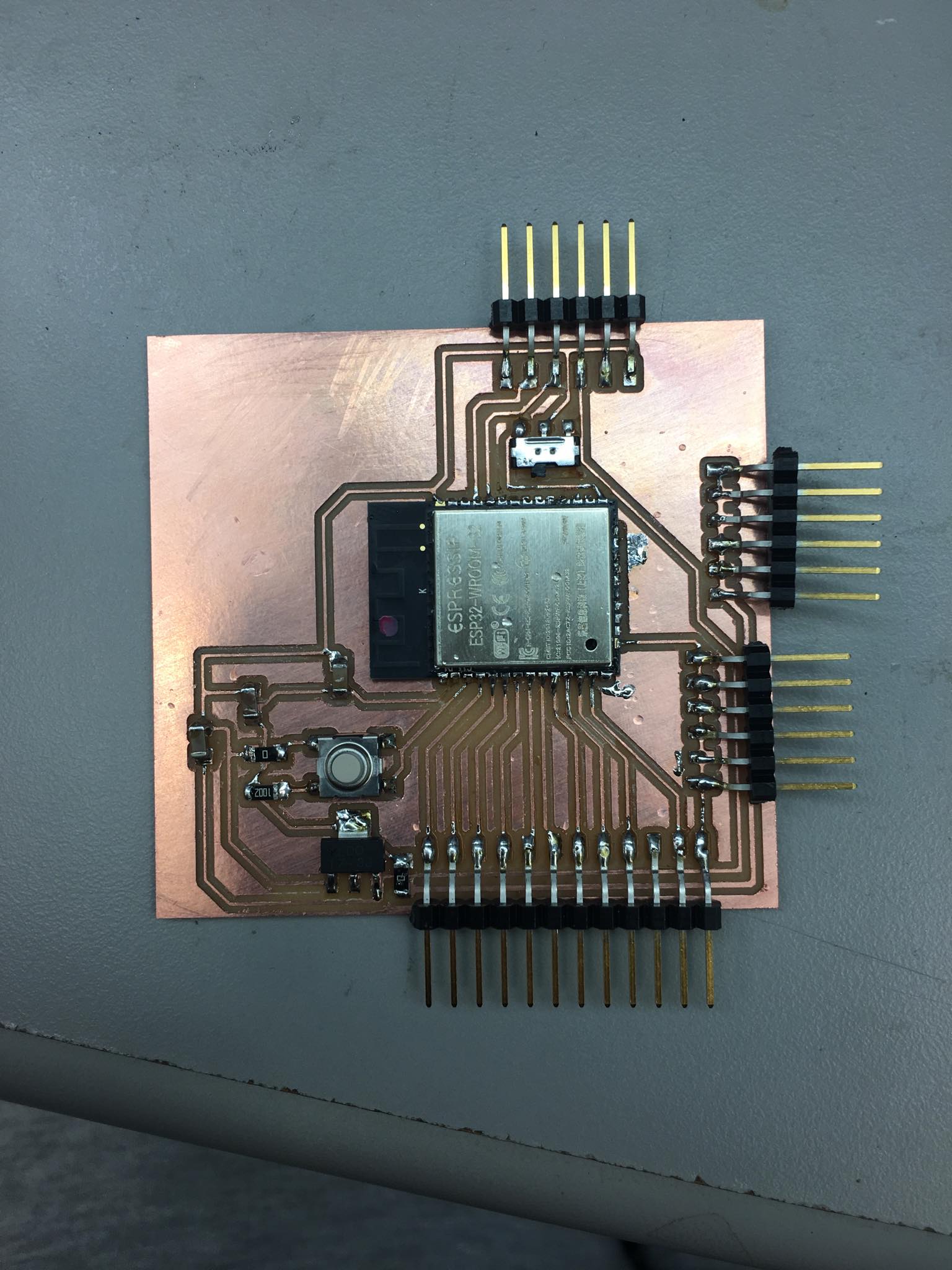
I milled and soldered the board according to the schematic from above.
Programming and Testing

I first tested the web server connection by using Neil's code and verified that my device could successfully connect to the internet. In order to upload the code I needed to first add the board into the Arduino library. A link that walks you through this is here.

I then tested the other pins on my board by programming a basic distance calculator for the ultrasonic sensor. In order to understand how the esp32 pins translate to GPIO pins in arduino you can visit this link.