Week 06: ELECTRONICS PROGRAMMING
A. BOARD DESIGN (TRY #1)
A1. Still trying for a working board...lesson in growth mindset
1.1 So because I'm quite beginner I have not yet been able to fabricate a working board, so sadly do not have the ability to program one of my own boards yet. I spent the past week trying to debug my board from week 4 and decided that this week I would try to re fabricate a simpler board from week 4 and program the basic LED and button functions
1.2 Unfortunately the new board I made become unsalvageable after much re soldering, wire hacks, and ripping up of traces. Below I walk through the process of building this board, and next week will try again! And hopefully after all the lessons I learned this week my fourth try will be successful!!
1.3 It can be super super discouraging when starting electronics design as a beginner. However, although none of my boards have worked (yet!) I have still learned SO much about what not to do, and each time it gets a little easier. Even though I have not had a complete success yet I have definitely not failed! Electronics design has been a huge lesson in practicing growth mindset because although it feels impossible and I'm constantly reminded of how little I know, with each try I get a little better and a little more confident.
A2. New board design in Eagle
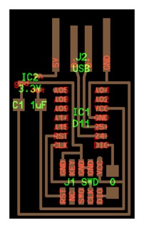
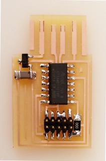
2.1 After talking with a few classmates I realized that Jake's tutorial was very very advanced, and I may have more success if I start simpler. I decided to choose one of Neil's boards, specifically the echo.hello.10 board. First I downloaded the board diagram and photos of the components to have something to go off of.
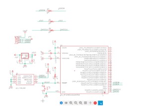
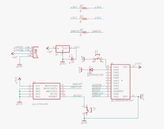
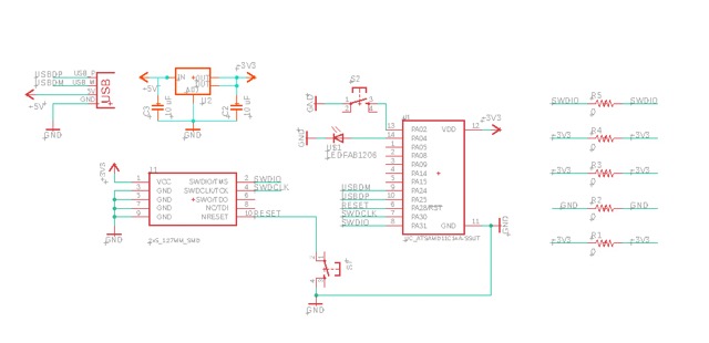
2.2 After week 4 I'm not much more familiar with working in Eagle and have started to get the hang of board design without following a tutorial step by step. I followed the board design (on the top left) to know which components to add to my schematic and also loosely followed my board design from week four (bottom left) to know which pieces should be connected. My re-created echo.hello.10 schematic is on the bottom right.
2.3 The schematic has a USB connector which is connected to ground, +5V, USBDP, and USBDM. The Microcontroller is connected to ground, +3V3, USBDP, USBDM, SWDIO, SWDCLK, and reset. My pinhead is connected to ground, +3V3, SWDIO, SWDCLK, and reset. Lastly, my voltage regulator is connected to ground, +5V, +3V3, and a 1 uF capacitor.
A3. Adding LED + buttons
3.1 Next I had to add my extra components that are in addition to the ones on Neil's board.
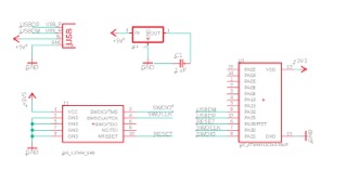
3.2 First was a reset button which I connected by adding a switch connected the reset on my pin head to the ground on my microcontroller.
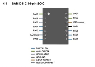
3.3 Then I added my LED button to a microcontroller pin, using the datasheet to determine which pin to connect to. Another success is that I've finally learned how to read a datasheet! I connected my LED to the PA04 pin and then to ground on the other side.
3.4 Lastly, I added my LED button to another pin on the microcontroller, PA02, and connected the other side to ground. Now we have all our components on the schematic!
A5. Routing
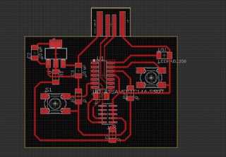
5.1 Now its time for routing, I again followed the same steps as in week 4. I modeled my basic layout off of Neil's board.
5.2 I did have to add three 0R jumps in order to make all of my routing work out.

A6. Exporting
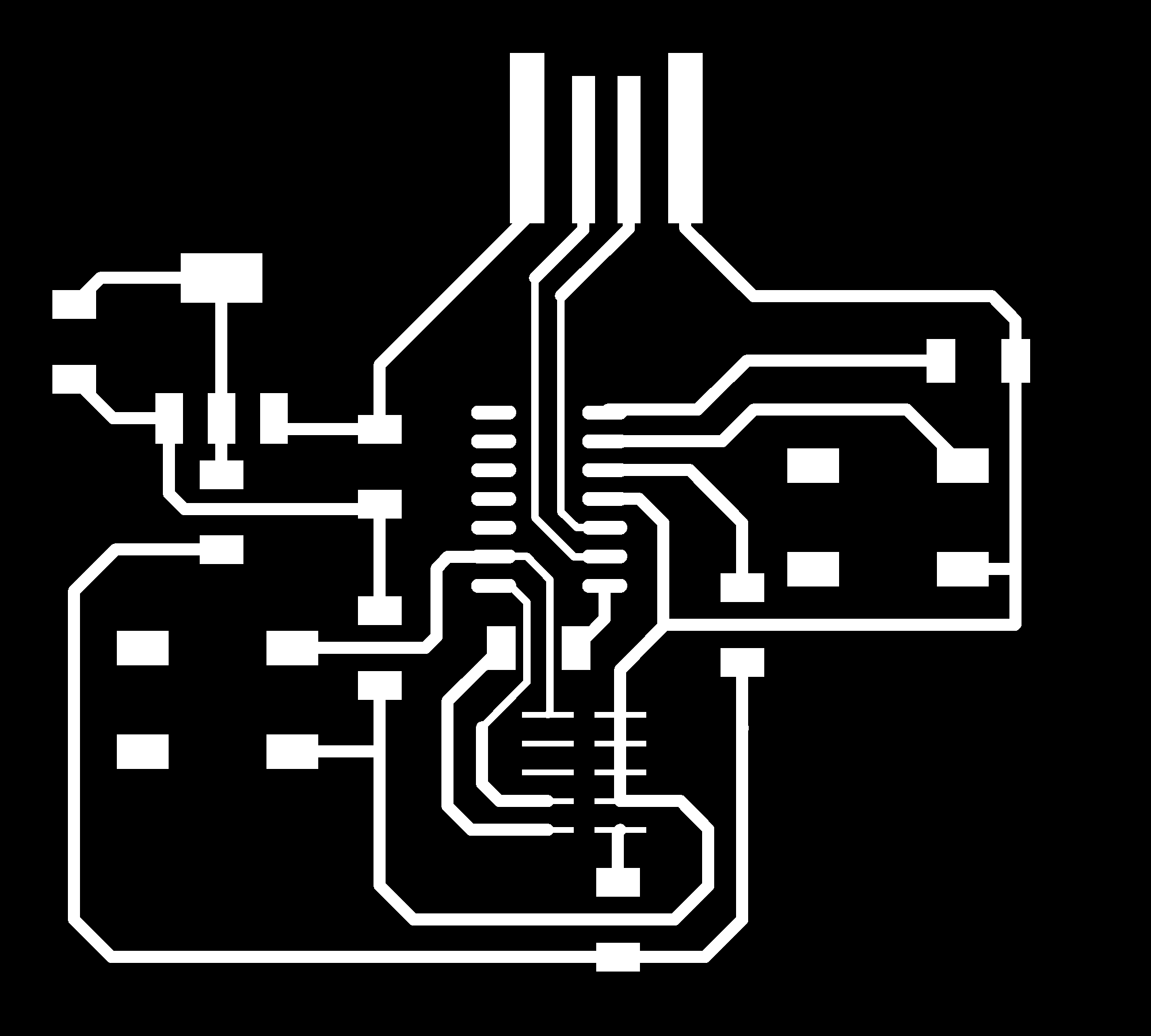
6.1 Next I exported my boards using the same commands as in week 4. because I don't have vias I only needed two pngs, one of my traces, one of my outline.
B. BOARD FABRICATION (TRY #1)
B1. Milling
1.1 For milling I followed the same steps from week 2 and 4. By now I'm pretty comfortable with the milling machine so this didn't take to long.
1.2 This was however my first time doing 4 offset instead of 0 which means that I didn't mill out all of the negative space in the interest of time.
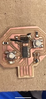
1.3 Because there was excess copper I ended up having to scrape some of it off with an exacto knife to make sure some of my traces didn't unintentionally connect and to clear off the USB port.
B2. Soldering
2.1 I tried to be very meticulous when soldering because the soldering is where all of my boards went wrong in the past. I used a multimeter to check my solder connected after I joined each component. I followed my design on eagle to know which pins should connect to which traces.
2.2 Unfortunately my traces were a little too small and I ended up ripping up about 6 off them throughout my time soldering.
2.3 At first I could remedy my ripped up traces by using wire to connect components to traces, however after trying to clean up some solder with the rosin braid and ripping off an entire foot of my microcontroller, I decided it may be time to start a new board.
B3. Lessons going forward
3.1 THICKER TRACES! Oh gosh my traces were so tiny they ripped of so easily so for my next board I'm going to use much thicker traces.
3.2 Use a bigger pin head! From comparing with a classmate I realized there is a mini 2 x 5 pin head and a large one. I've been using the mini one because it was what Jake used in the tutorial but it is sooo hard to solder because the traces are so tiny. For my next board I'm going to use the larger pinhead to hopefully make soldering easier.
C. BOARD DESIGN (TRY #2)
C1. Design in Eagle
1.1 I remade my board in Eagle and made sure to use thicker traces, and route my wires in strategic ways that would make soldering easier.
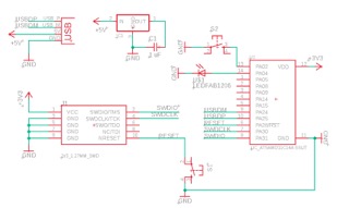
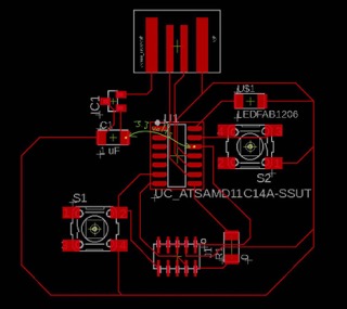
1.2 I used the SAMD11C microcontroller along with the 5x2 pinhead, a reset button, an LED, a button for the LED, voltage regulator with two capacitors, and the USB connection. Along with 5 0R to help with wire routing.
1.3 I first set up all my pieces in the schematic diagram and then moved to the PCB diagram to route my wires. I made my traces .6 mm thick, and only went as thin as .4 mm when I was routing traces under a component so that I would be sure to not accidentally connect them when soldering.

C2. Export in Photoshop
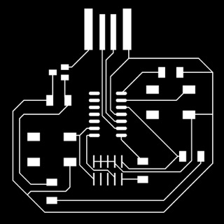
2.1 After I was happy with my design I exported the images and created my trace and interior files in photoshop.
D. BOARD FABRICATION (TRY #2)
D1. Milling + Soldering
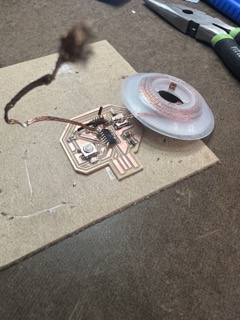
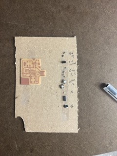
1.1 Followed the same steps as I did previously to mill my board.
1.2 Also followed the same steps as previously to find all of my components and then solder them onto the board. Overall, my soldering has gotten a lot better so its much easier to assemble my boards without messing them up!
E. BOARD PROGRAMMING (TRY #2)
E1. Bootloading board
1.1 To bootload my board I connected the usb to the shop computer, and the 5x2 pinhead to the etmel ice.
1.2 Then I opened the shop computer and downloaded the binary file for my SAMD11C microcontroller.
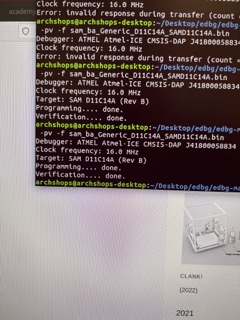
1.3 Lastly, I went to terminal and navigated to edbg files and flashed the binary files onto my board. I had a lot of help from my TA Reina for this.
E2. Programming board
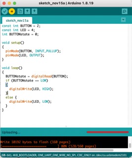
2.1 First I had to set up my Arduino by downloading the microcontroller types from the fab website and importing them. I then had to set the board and microcontroller types to match the ones I was using.
2.2 Then I plugged in my board to my computer's usb and went to the port in Arduino to see if Arduino recognized my board. It did! Which means I am all set to send code to my board to program it.
2.3 I found the code to program my board online and just changed the pin values to match the pins I connected my LED and button to on my board.
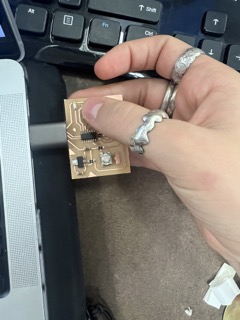
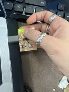
2.4 Then I verified and uploaded the code to my board and it worked! I had to fiddle around with the code a little more to program my board so that the light would go off when the button was pressed rather than the other way around.
2.5 Below are photos of my working board, with the button unpressed (left) and pressed (right).