Week 01: Computer Controlled cutting
A. VINYL CUTTING
A1. Choosing my design
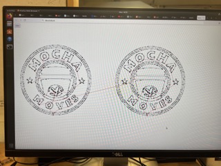
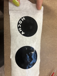
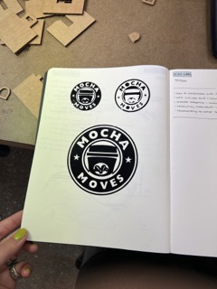
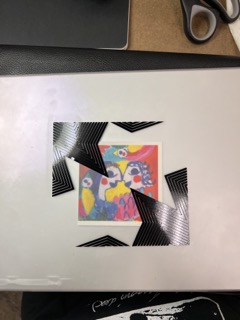
1.1 I decided to try one simpler design and one more complex one to see how hard it is to cut intricate lines and details. My first design is the logo for my dance team (mocha moves), and second design is an altered logo I made earlier this year for an event
A2. Cutting my design
1.1 First you want to upload your jpg or png to the computer, make sure it is black and white and good resolution. My dance team logo had low resolution so the vinyl cutter literally cut the fuzzy edges out.
1.2 Next I used the mods tab for vinyl cutting to upload my jpg, set the size, and calculate the cut path
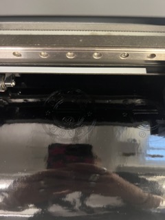
1.3 Before sending your file to cut, set the origin on your machine using the directional arrows and make sure the vinyl is pulled through the machine enough to cover the sensor.
1.4 Next, you upload your jpg file to the mods on the computer next to the vinyl cutter. Hit calculate to get your final file.
1.4 Now you are ready to cut! Send your calculated mods file to the printer and it will start cutting.
A3. Peeling my design
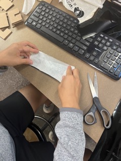
1.1 First you want to remove your design from the machine by cutting the vinyl, try not to waste material and only cut in close proximity to your design
1.2 Next you want to take the transfer paper and press it onto your design, make sure you press it down fully
1.3 Then you are going to peel the transfer paper off of the vinyl backing and your design should detach from the backing and stay connected to the transfer paper. I found its easier to do this if you instead flip the vinyl and transfer paper and instead peel the vinyl backing off of the transfer paper, instead of the other way around.
1.4 Once your vinyl design is on the transfer paper you can start removing the unwanted bits with a tweezer. The first time I tried to do this I realized I printed my pieces way too small and it was very tricky to remove the pieces I wanted with out messing up the others. I reprinted a larger size and it worked a lot better!
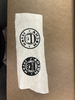
1.5 One of my favorite parts of the vinyl cutter is that you can really play around with the negative parts of your design and which pieces you want to remove and keep. I printed my logo design twice so that I could make one that was the original design and one that was the inverse.
B. LASER CUTTING
B1. Idea
1.1 I'm very familiar with rhino and have always wanted to learn Grasshopper, so I decided that that would be my program of choice for parametric designing.
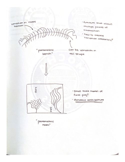
1.2 For my final project I want to produce dynamic and interactive spaces, so for this project I experimented with grasshopper to create iterations of parametric benches. The bench's form is derived parametrically and the different forms allow for multiple points of interaction and use.
B2. Learning Grasshopper!
2.1 While I've done lots of normal rhino modeling I've never done parametric modeling, so I used a grasshopper tutorial I found online to learn how to use Grasshopper and how to create a parametric bench.
Tutorial Link: https://www.youtube.com/watch?v=3Fkdi8RuwN8)
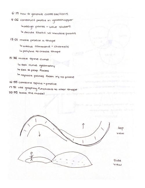
2.2 I first modeled a rough shape of what I wanted my control bench cross section to look like, or profile.
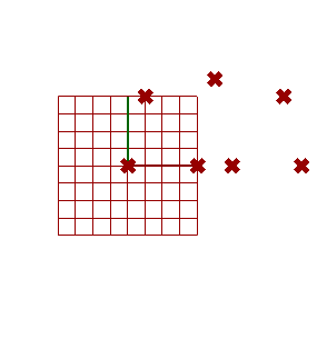
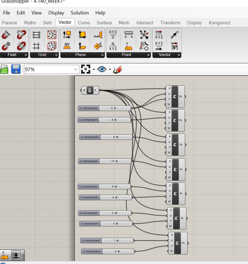
2.3 Then I had to create my shape in grasshopper by creating and setting all of the points.
2.4 To connect the point into a joined shape I used the weave command so that grasshopper recognizes my points as a whole shape.
2.5 Next I modeled the rail of my bench that the cross sections would run along. To do this I drew a curve in rhino and then connected my grasshopper rail block to it. While iterating through different forms I eventually found it hard to create the shape I wanted on a curved rail, so I modeled the bench on a straight rail and then introduced the curved aspect later during fabrication and assembly.
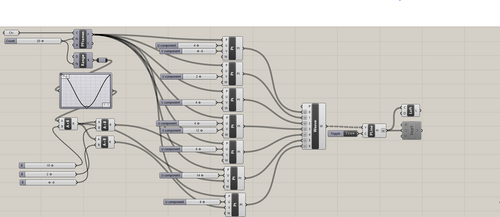
2.6 I then combined the spine blocks to the profile blocks and set the number of perpendicular faces I wanted, i.e. how many profiles run along the spine.
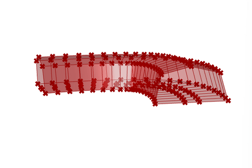
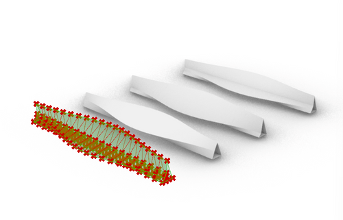
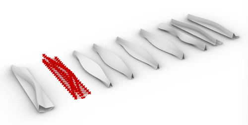
2.7 Lastly I connected some of the top points of my profile to a graphing function in grasshopper so that I could ideate different forms based on different mathematical functions, for example one of my final models is a sine curve and another is a gaussian curve.
2.8 Once you generate a shape you like in grasshopper you have to bake it to turn it into an actual solid in rhino.
B3. Turning into laser cut files
3.1 After generating my bench model forms in rhino, I realized that my models didn't go together multiple ways. Therefore, I decided to fabricate multiple rail options with different levels of bend-ability based on how dense the score marks were. Now the benches can be assembled with static or dynamic rails. The benches cross sections can also be moved and reversed orientation to offer multiple seating options. In addition the cross sections are able to slide along the rails, again allowing more flexibility and versatility in the amount and type of seats.
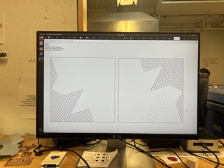
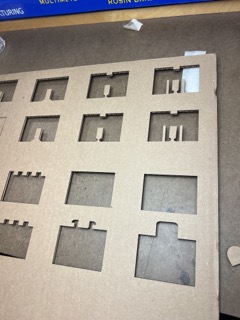
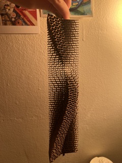
3.2 To generate laser cut files for the rails I just drew some rectangles to size and made different iterations of score density so I could test rails of differing flexibility.
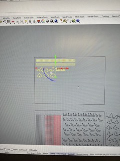
3.3 To generate the laser cut file for the bench cross sections I divided up my form models that I created in grasshopper and then duplicated the border of each face and spread them out in order so that I could keep track of the order of profiles along the rail.
B4. Laser cutter calibration and testing
4.1 I've used the laser cutter a lot of times before for different architectural projects so am familiar with the power and speed settings as well as using color mapping. I used the power and speed settings listed in the architecture shop above the laser cutters. For color mapping I just set all of my score marks to a different line color than the cut marks and then set the power/speed of those colors respectively.
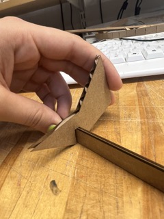
4.2 For the group assignment we did one test where we tried different power and speeds on the cardboard, and another test where we cut different types of joints. The second test wasn't super successful because the file was scaled incorrectly so I did my own iterative tests to find the best joint width for my cross section pieces.
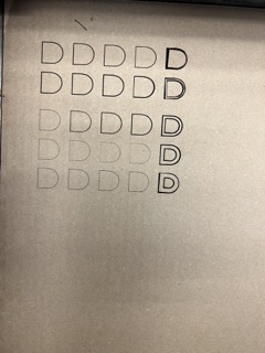
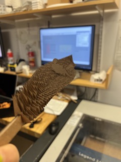
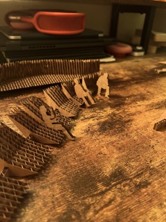
4.3 I needed to find the correct joint width so that my cross section pieces fit snuggly on the rail but also had the ability to be slid or moved to different locations on the rail. To do this I printed cross section pieces at multiple different sizes and attached them all to a test rail to determine which cross section size was the best. Although the cardboard is .1875" thick I found that a joint thickness of .145" worked best. This is because my rails were so thin that the interior structure of the cardboard would collapse, making the overall depth of the cardboard thinner.
4.4 I also had to test out different density of score lines to see which bending quality I liked best for my bench. The larger density of score marks were too frequent and the distance between scores was smaller than the distance between the interior corrugation so the two exterior pieces of the cardboard would detach from the interior corrugation.
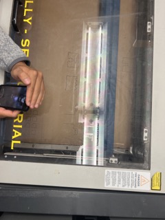
B5. Laser cutting my project
5.1 Once I found the correct joint width I resized all my pieces to match that and sent it to the laser cutter.
B6. Assembling my project
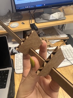
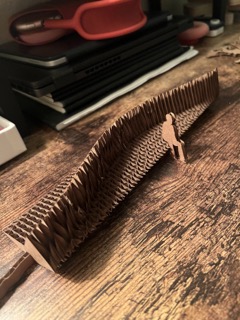
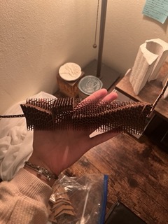
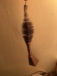
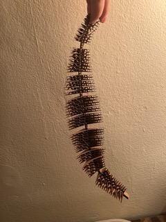
6.1 After I had all my pieces cut, I placed the cross sectional pieces on different rails to test out the flexibility.
6.2 I also tried sliding the cross sectional pieces along the rails to generate different seating formations.
6.3 Lastly, I changed the orientation of the cross sectional pieces to again create more variation in seating and interaction options for the user.