Week 10: NETWORKING + COMMUNICATIONS
A. BOARD DESIGN
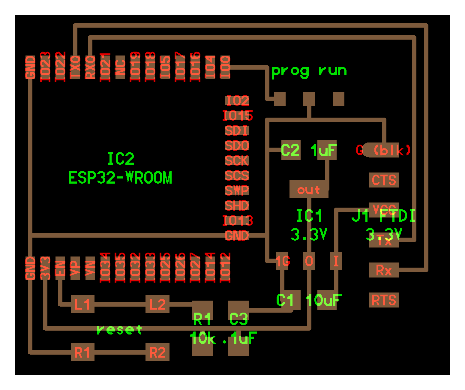
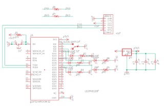
A1. Design in Eagle
1.1 For this week I decided to try out the ESP32 microcontroller in order to wirelessly communicate with my computer. I knew that I wanted to use wireless communication for my final project so this was a great way to prototype on which microcontroller I wanted to use to do that.
1.2 I modeled my board design off of Neil's ESP32-WROOM board (found on his website) and then added 5 LEDs and resistors so that I could turn the different LEDs on wirelessly from my computer.


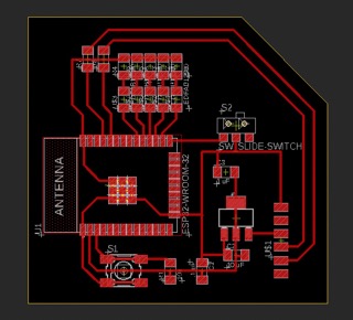
A2. Export in Photoshop
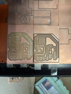
2.1 Then I exported my board design and used photoshop to generate the trace and interior pngs.
B. BOARD FABRICATION (TRY#1)
B1. Milling + Soldering
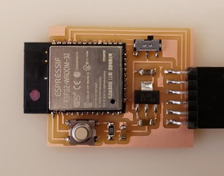
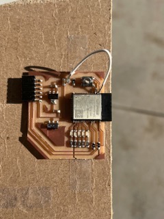
1.1 I milled and solder my board following the same process as in week 2.
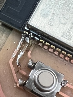
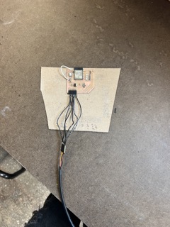
1.2 The ESP32 was super super hard to solder because it had a ton of tiny pins that were very close to each other, as you can see in the photos I soldered together a bunch of my traces on the first board I milled. I tried to do some debugging by adding a white wire to connect some traces I ripped up when trying to desolder with the copper braid.
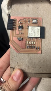
1.3 The second board I milled I tried to be a lot more careful while soldering. Overall I tried to use less solder and to check my connections with the multimeter after every solder.
C. BOARD DEBUGGING + PROGRAMMING


C1. Writing the code
1.1 To write my code I modified the code from my week 6 LED + button board. I programmed it so that you could input numbers 1 - 5 through the serial monitor and those numbers would correspond to one of the LEDs on the board.
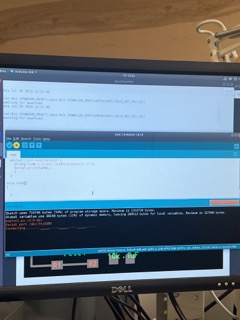
1.2 Unfortunately I wasn't able to test if the code worked because I had a lot of trouble getting the ESP32 board to connect to the arduino and be able to upload a sketch.
C2. Programming my board
2.1 I tried programming both of my boards and both had issues connecting to arduino. At this point the class was wrapping up and I was turning my attention to the final project. I used a bluetooth component in my final project so was able to finally get a functioning networking device then.
D. WORKING BLUETOOTH MODULE IN FINAL PROJECT...
1.1 For my final project I tried to use an HC-05 bluetooth module to communicate serial data from the sensor connected to my board back to my computer. I was able to get the bluetooth module functioning briefly on my computer, and semi-consistently on the EECS TA Anthony's computer. However, I ultimately decided to demo the project using a USB connection because the bluetooth connection from the HC-05 to mac is pretty unreliable.