Week 08: INPUT DEVICES
A. BOARD DESIGN
A1. Design in Eagle
1.1 For my input + output devices I ended up putting them on the same board because I was pretty behind with electronics (had many weeks of failed soldering and buggy boards). I decided to use piezoelectric sensors because they have a similar function to what I want for my final project.
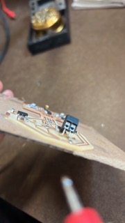
1.2 The input device of my board is the piezo sensor, which I connected using the terminal block component. I also added an LED to eventually use for my output device, but I go into more detail on that in week 9.
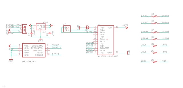
1.3 In my schematic I included the SAMD11C microcontroller, the 5x2 pinhead, a voltage regulator and capacitors, a USB connection, and then I connected a terminal block and LED to analog pins on my microcontroller. I also added 7 0R to help with routing.
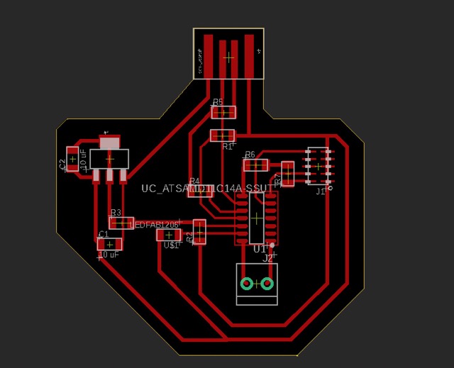
1.4 Then I went to the PCB board design, and arranged all my components and routed them using the same workflow and trace widths as in week 6.


A2. Export in Photoshop
2.1 Then I exported my board design and used photoshop to generate the trace and interior pngs.
B. BOARD FABRICATION
B1. Milling + Soldering
1.1 I followed the same milling steps I detailed in week 2.
1.2 I also used the same soldering workflow as in week 6.
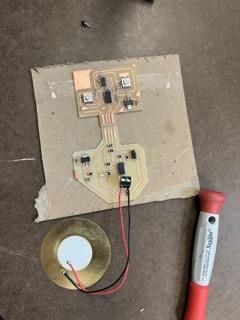
1.3 The one tricky component to solder on was the terminal block. I just used solder to connect the two bottom pins to the GND and VCC charges. Then I put the GND and VCC wires from the piezo sensor in their respective holes on the terminal block and tightened them into place using a flathead screwdriver.
1.4 Another thing I've started doing while soldering that has really helped is using the multimeter to check that all of my connections are working every time I solder a new one. It helps ensure suitable soldering and lessen debugging time.
C. BOARD PROGRAMMING
C1. Flashing my board
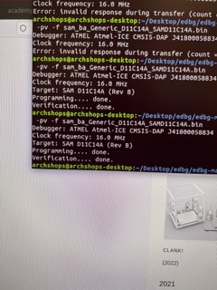
1.1 I followed the same steps as in week 6 to flash the edbg binary files onto my board. It worked! Which means my board is now ready to me plugged into my own computer and programmed in Arduino.
C2. Programming my board
2.1 I based my code off of this reference and Reina, my TA, helped me with modify it for my specific board.
Tutorial Link: https://create.arduino.cc/projecthub/SBR/working-with-an-led-and-a-push-button-71d8c1
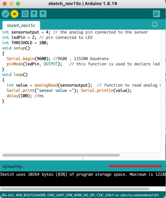
2.2 I first made sure to set the different variable to the correct pins that the components were connected to on my board.
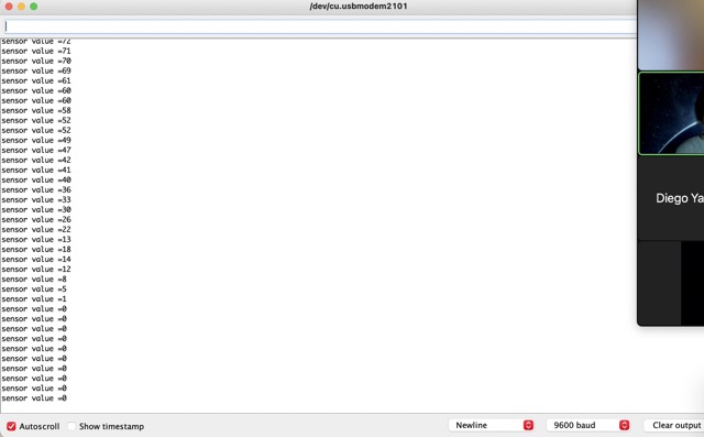
2.3 The Reina helped me program a serial print, so that the board would produce values from the piezo sensor every 100 ms.
2.4 Photos of the working serial print are below! Still haven't fully gotten the hang of how the sensor itself actually works, so will have to do a little bit more investigation before deciding what I use in the tension ties for my final project.